
24V Power PVC Drag Chain Cables: Engineering Reliable Motion Control in Industrial Automation
Discover the 24V POWER PVC / 24V POWER + FE PVC high-flex drag chain cable—compliant, finely stranded bare copper for reliable 24V power transmission in automotive, machine tools, and continuous-motion setups. Oil-resistant, drag-chain optimized up to 10m travel.
hongjing.Wang@Feichun
2/11/202611 min read

In the heart of a modern automotive assembly plant, robotic welding arms execute thousands of precise movements daily, their continuous motion demanding uninterrupted power delivery through cables that bend, twist, and flex millions of times over their service life. Similarly, in CNC machining centers and automated packaging lines, moving gantries and tool changers require electrical connections that can withstand relentless mechanical stress while maintaining consistent 24V power transmission. These demanding applications require specialized cabling solutions designed specifically for dynamic environments—enter the high-flex drag chain cable engineered for continuous motion applications.
The 24V POWER PVC cable family represents a purpose-built solution for industrial automation systems requiring reliable low-voltage power delivery in constantly moving machine components. Available in both 4-core and 5-core configurations (the latter incorporating a functional earthing conductor), these cables meet stringent network communication standards while delivering the mechanical durability essential for drag chain installations. Constructed with silicone-free, oil-resistant PVC materials, they provide dependable performance in the dry and wet industrial environments typical of manufacturing facilities, though not suitable for outdoor exposure.
Conductor Engineering: The Foundation of Flexibility
At the core of any high-performance drag chain cable lies its conductor construction, and this is where specialized engineering makes the critical difference between premature failure and extended service life. The 24V power cables utilize bare copper conductors manufactured to DIN VDE 0295 class 5 and IEC 60228 class 5 specifications—standards that define "finely stranded" conductor construction.
This classification isn't arbitrary. Class 5 conductors feature significantly more individual copper strands than standard building wire, with smaller individual strand diameters that dramatically improve flexibility. For a 1.5 mm² conductor, for example, class 5 construction might incorporate over 30 individual strands compared to just 7-19 strands in less flexible class 2 construction. This fine stranding reduces the mechanical stress on individual copper elements during bending cycles, distributing flexing forces across many more contact points and preventing the work-hardening and eventual breakage that plagues cables with fewer, thicker strands.
The conductor cross-sections available—0.75 mm², 1.5 mm², and 2.5 mm²—cover the typical current-carrying requirements for 24V power distribution in industrial control systems, sensors, actuators, and auxiliary equipment. The bare copper construction (without tinning or plating) provides excellent electrical conductivity while the fine stranding ensures the cable maintains its flexibility even after millions of bending cycles.
Insulation and Identification: Ensuring Reliability and Safety
Each conductor is individually insulated with PVC compound type TI3, conforming to DIN VDE 0207-363-3 and DIN EN 50363-3 standards. This specific PVC formulation balances several critical properties: adequate dielectric strength for 300/500V nominal voltage rating, sufficient flexibility to accommodate repeated bending without cracking, and resistance to the oils and coolants commonly encountered in industrial machinery.
The core identification scheme follows established color coding conventions that facilitate installation and troubleshooting. In the 4-core configuration, conductors are color-coded brown (L1), blue (N1), black (L2), and white (N2)—allowing for dual 24V circuits or alternative wiring configurations as system requirements dictate. The 5-core version adds a rose-colored functional earthing conductor (FE), providing protective grounding in accordance with DIN EN 60445 (VDE 0197).
This functional earth connection represents an important safety consideration in automated systems. While 24V circuits themselves present minimal shock hazard, the metal frames, enclosures, and moving parts they power can develop dangerous potentials through induction, capacitive coupling, or insulation degradation. The dedicated earthing conductor ensures these metal components remain at ground potential, protecting both equipment and personnel.
A nonwoven wrapping layer applied with minimum 25% overlap surrounds the insulated conductor bundle, providing mechanical separation and maintaining core geometry during flexing. This seemingly minor detail plays an important role in cable longevity—without proper core bedding, individual conductors can shift position during movement, creating uneven stress distribution and accelerating wear.
Outer Sheath: Protection Against Industrial Environments
The cable's outer sheath utilizes PVC compound type TM3 per DIN VDE 0207-363-4-1 and DIN EN 50363-4-1, formulated specifically for demanding industrial applications. This sheath material demonstrates extensive oil resistance—a critical property when cables operate in proximity to hydraulic systems, machine lubrication points, or coolant delivery systems common in manufacturing environments.
The sheath formulation is free of silicone, cadmium, and paint-wetting impairment substances. The silicone-free composition is particularly important in automotive and aerospace manufacturing, where even trace silicone contamination can cause catastrophic paint adhesion failures during finishing operations. The absence of cadmium addresses environmental and health concerns, while freedom from paint-wetting impairment substances ensures the cable won't interfere with coating processes.
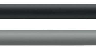
Color coding differentiates the two cable variants: the 4-core version features black sheath (RAL 9005), while the 5-core cable with functional earthing conductor uses gray (RAL 7001). This visual distinction helps installation teams and maintenance personnel immediately identify which cable type is installed, reducing the risk of improper connections or grounding errors.
White meter markings printed on the sheath at regular intervals serve multiple practical purposes. During installation, these markings help installers track cable consumption from reels, estimate remaining stock, and document installation lengths. For maintenance and troubleshooting, the markings provide reference points for identifying damage locations or measuring cable replacement sections.
Drag Chain Performance: Engineered for Continuous Motion
The true measure of a drag chain cable lies in its ability to withstand the mechanical punishment of continuous motion applications. The 24V power cables are specifically designed and tested for installation in drag chain systems with clearly defined performance parameters:
Maximum traveling distance: 10 meters represents the longest horizontal or vertical travel span the cable can reliably serve. This limitation reflects the cumulative mechanical stress imposed by the cable's own weight and the friction forces within the drag chain carrier. Exceeding this distance can lead to premature conductor fatigue, particularly in the sections experiencing the greatest tensile loading.
Maximum speed: 3 meters per second defines the upper limit for linear carriage velocity. At higher speeds, dynamic forces—including acceleration-induced tensile peaks and the vibration generated by rapid direction changes—can exceed the cable's mechanical design limits. Additionally, faster motion generates more heat through friction within the drag chain, potentially affecting insulation properties.
Maximum acceleration: 3 m/s² sets the boundary for how quickly the moving system can change velocity. High acceleration creates shock loads that propagate through the cable structure, with peak forces many times greater than static weight. These impulse loads represent one of the most damaging force types cables experience in motion applications.
Maximum cycles: 2 million cycles define the expected service life under specified conditions. A "cycle" typically represents one complete back-and-forth movement of the drag chain system. For a machine operating continuously at one cycle per second, this translates to approximately 23 days of operation—highlighting why proper cable selection and installation are crucial for minimizing downtime in high-duty-cycle applications.
The minimum bending radius specifications—12 times the cable outer diameter for flexing applications and 4 times for fixed installations—stem from fundamental material mechanics. Tighter bending radii impose higher strain on the outermost cable elements, accelerating insulation cracking and conductor fatigue. The 12x ratio for dynamic applications provides adequate safety margin against these failure modes, while the more relaxed 4x ratio for stationary installations reflects the absence of cyclic stress.

Temperature Performance and Environmental Resistance
Operating temperature ranges differ significantly between flexing and fixed installation scenarios. For flexing applications, the cable operates reliably from 0°C to +90°C, while fixed installations can tolerate a broader -30°C to +90°C range. This distinction reflects the different mechanical behaviors of PVC insulation and sheath materials at temperature extremes.
At subfreezing temperatures, PVC becomes increasingly rigid and brittle. While this presents minimal concern for stationary cables, the repeated bending cycles in drag chain applications could induce cracking or conductor damage if the cable were flexed below its minimum flexing temperature. The 0°C lower limit for dynamic use provides safety margin against cold-weather startup conditions or temporary ambient temperature excursions.
The upper temperature limit of +90°C addresses both electrical and mechanical considerations. From an electrical perspective, conductor resistance increases with temperature, causing greater I²R heating for a given current load. Mechanically, elevated temperatures soften PVC materials, potentially accelerating wear in drag chain applications where the cable slides against carrier surfaces.
The extensive oil resistance noted in the specifications encompasses a wide range of industrial lubricants, hydraulic fluids, and coolants. However, "oil resistance" is not absolute—it depends on specific chemical compositions, exposure durations, and temperatures. For applications involving continuous immersion in aggressive chemicals or exposure to solvents not typically classified as "oils," chemical compatibility testing is advisable.
Electrical Ratings and Safety Compliance
The nominal voltage rating of U₀/U 300/500V (where U₀ represents the voltage between conductor and ground, and U represents the voltage between conductors) provides substantial safety margin for 24V power distribution applications. This overrating ensures the insulation system maintains its integrity even under fault conditions, voltage transients, or aging effects that might otherwise compromise lower-rated cables.
Flame retardancy testing per DIN VDE 0482-332-1-2, DIN EN 60332-1-2, and IEC 60332-1-2 verifies the cable's behavior when exposed to a standardized ignition source. These single-vertical-wire flame tests assess whether a cable will continue burning after the ignition source is removed and whether burning particles drop from the specimen. Passing these tests means the cable won't propagate fire along its length under the test conditions, though it's important to note these are minimum safety requirements—installations in critical applications may require additional fire protection measures.
Compliance with the Low-Voltage Directive 2014/35/EU confirms the cable meets essential health and safety requirements for electrical equipment operating between 50 and 1000V AC (or 75 to 1500V DC). This CE marking indicates the manufacturer has assessed the product against applicable harmonized standards and maintains technical documentation demonstrating compliance.
Industrial Applications: Where These Cables Excel
The 24V power PVC drag chain cables find their primary applications in industrial automation systems where moving machine components require reliable electrical connections. Understanding these application contexts helps engineers select, install, and maintain these cables properly.
Automotive Manufacturing: Robotic welding systems, automated paint lines, and assembly conveyor systems all incorporate moving components requiring power delivery. Spot welding robots, for instance, feature multi-axis arms executing thousands of precise movements daily, with tool changers and auxiliary equipment demanding continuous 24V power. The oil resistance and silicone-free construction prove particularly valuable in automotive environments where contamination control is critical.
Machine Tool Construction: CNC machining centers, turning centers, and milling machines employ moving gantries, tool magazines, and workpiece handling systems. The coolant-rich environment of metalworking operations places special demands on cable materials, making the oil-resistant PVC construction particularly suitable. The high cycle life supports the continuous operation typical of production machining, where machines may operate unmanned for extended periods.
Packaging and Material Handling: High-speed packaging machinery, automated storage and retrieval systems, and conveyor networks all rely on moving electrical connections. These systems often operate continuously in multi-shift production environments, accumulating millions of motion cycles annually. The cable's 2-million-cycle rating helps ensure reliable operation between scheduled maintenance intervals.
Measurement and Control Systems: Industrial sensors, actuators, and control devices frequently mount on moving platforms requiring flexible power delivery. Level sensors on filling equipment, position encoders on linear actuators, and proximity switches on automated gates all represent typical applications. The dual-circuit capability of the 4-core configuration allows powering multiple devices from a single cable run.
Installation Guidelines: Maximizing Cable Life
Proper installation is equally important as correct cable selection in achieving long service life. Several critical factors deserve attention during drag chain installations:
Drag chain sizing: The drag chain carrier should provide adequate internal space for the cable to move freely without jamming or excessive compression. As a general guideline, cable fill should not exceed 50-60% of the drag chain's internal cross-sectional area, allowing room for cable movement and preventing mechanical interference.
Cable routing: Within the drag chain, cables should be routed to minimize crossing or twisting. When multiple cables share a carrier, they should be separated by dividers or arranged to prevent entanglement. The neutral axis of the drag chain—the theoretical line that maintains constant length during bending—should align with the cable's center when possible, minimizing tensile and compressive stresses.
Support and fixation: Both ends of the cable must be properly secured with appropriate strain relief. The fixed end should be clamped firmly to prevent movement, while the moving end should allow limited axial motion to accommodate the cable lengthening and shortening that occurs as the drag chain bends and straightens. Without proper strain relief, connection terminals experience mechanical stress that can loosen connections or fracture conductors.
Bending radius enforcement: Drag chain systems must be configured to prevent the cable from bending tighter than its minimum radius specification. This typically involves selecting drag chain carriers with appropriate link sizes and configuring system geometry to maintain adequate curve radii throughout the travel range.

Common Installation Challenges and Solutions
Problem: Premature conductor failure at the cable ends
This issue typically stems from inadequate strain relief allowing repetitive flexing to concentrate at connection points. The solution involves implementing proper cable management at both fixed and moving terminations. Industrial cable glands with integrated strain relief should be used at the fixed end, while the moving end requires special attention—many installations benefit from a short length of even more flexible cable (sometimes called a "whip" or "pigtail") between the main cable and the equipment connection, providing a gradual transition in flexibility.
Problem: Accelerated sheath wear in drag chain
Excessive friction between cable and drag chain surfaces can rapidly abrade the outer sheath, particularly at high speeds or long travel distances. Contributing factors include undersized drag chain carriers (forcing the cable into tight contact with internal surfaces), contamination (abrasive particles acting like grinding compound), and insufficient lubrication. Solutions include verifying adequate cable clearance within the carrier, implementing proper drag chain sealing to exclude contaminants, and applying appropriate lubricants if recommended by the drag chain manufacturer.
Problem: Cable "corkscrewing" or twisting during motion
This phenomenon occurs when installation methods or system geometry allow the cable to rotate around its longitudinal axis during drag chain movement. The twisting motion introduces additional mechanical stress and can lead to conductor bunching, insulation damage, or premature failure. Prevention requires proper cable fixation at both ends, ensuring the cable cannot rotate at its mounting points. Some installations benefit from twist-resistant cable designs or special drag chain configurations that mechanically prevent cable rotation.
Problem: Inconsistent electrical performance or intermittent connections
Electrical issues in drag chain cables often manifest as intermittent problems that defy simple troubleshooting. Partially broken conductors may make contact in some positions but open in others. Insulation damage may create intermittent short circuits. These issues frequently result from mechanical problems—improper installation, incorrect cable selection for the application, or operation beyond specified parameters. Systematic troubleshooting should examine installation conditions, verify specification compliance, and use cable testing equipment capable of detecting high-resistance connections or insulation weaknesses.
Maintenance and Inspection Considerations
Proactive maintenance extends cable service life and prevents unexpected failures. Regular visual inspections should examine the sheath for cuts, abrasions, or deformation. Any visible damage warrants investigation—even superficial sheath damage can admit contaminants or progress to conductor exposure.
Periodic electrical testing can identify degrading cables before complete failure. Insulation resistance testing (using a megohmmeter at appropriate voltage) reveals insulation deterioration, while conductor resistance measurements can detect partially broken strands. Comparing measurements over time helps establish trending data indicating when replacement may be necessary.
Operating condition documentation proves valuable for predictive maintenance. Recording actual travel distances, speeds, cycle counts, and environmental conditions allows comparison against cable specifications. When actual operating conditions consistently approach or exceed rated parameters, proactive replacement during scheduled downtime prevents disruptive emergency failures.
Selecting the Right Configuration
Choosing between 4-core and 5-core configurations depends on system grounding requirements and available equipment terminations. The 4-core cable suits applications where functional earthing occurs through alternative means—perhaps through the drag chain carrier itself, separate ground conductors, or systems where protective earthing isn't required. The 5-core configuration with dedicated functional earthing conductor provides a defined ground path independent of mechanical structures, offering enhanced safety and reducing the possibility of ground loops or noise coupling in sensitive control circuits.
Cross-sectional area selection balances electrical and mechanical considerations. While larger conductors carry more current with less voltage drop, they also reduce overall cable flexibility and increase weight—factors that can negatively impact drag chain performance. A 0.75 mm² conductor might suffice for low-current sensors and indicators, while 1.5 mm² represents a good general-purpose choice for typical 24V power distribution. The 2.5 mm² size suits higher-current applications like solenoid valves, motors, or multiple parallel loads, though the reduced flexibility and increased weight require careful consideration in high-cycle applications.
Conclusion: Engineering Reliability Into Motion Control
The specialized design of 24V power PVC drag chain cables addresses the unique challenges of industrial automation systems where continuous motion is fundamental to operation. Through careful attention to conductor construction, insulation materials, sheath protection, and mechanical performance specifications, these cables deliver the reliability essential for minimizing downtime in production environments.
Success in these demanding applications requires more than simply selecting a cable rated for drag chain use—it demands understanding the interaction between cable properties, installation practices, and operating conditions. By respecting minimum bending radii, implementing proper strain relief, maintaining appropriate drag chain fill ratios, and operating within specified parameters, engineers can achieve the millions of motion cycles these cables are designed to provide.
As industrial automation continues advancing toward higher speeds, longer travels, and more demanding duty cycles, the role of properly specified and installed cabling becomes increasingly critical. The 24V power drag chain cable represents proven technology for current applications while providing the performance headroom necessary for evolving system requirements. Whether powering robotic systems in automotive plants, enabling precision in CNC machining centers, or supporting high-speed packaging operations, these cables form the flexible electrical backbone enabling modern industrial automation.
How to Reach Us
Get in Touch
SiteMap
Product Catalogue
Festoon Cable
Shore Power Cable




Scan to add us on WeChat