
6kV Medium Voltage Reeling Cable Selection Guide: Optimising Heavy Mobile Equipment Performance in Australian Open-Cut Mining
Discover how to select the right 6kV reeling cable for mining shovel, excavator, and conveyor systems with guidance on current capacity, voltage drop, and mechanical stress.
hongjing.Wang@Feichun
7/23/202613 min read
Open-cut mining operations across Australia present some of the most unforgiving working environments on earth. From the relentless, scorching ambient temperatures of the Pilbara in Western Australia to the highly abrasive, dust-laden terrains of the Bowen Basin in Queensland, heavy equipment relies on uninterrupted power to maintain production targets. Electric rope shovels, high-capacity excavators, and mobile in-pit crushing and conveying systems require massive amounts of continuous energy to sustain high-tonnage output.
To deliver electrical power across large operating radiuses without constant generator relocation, mine sites rely heavily on reel-mounted flexible trailing cables. While low-voltage power distribution remains sufficient for smaller ancillary machines, high-tonnage mobile equipment demands medium-voltage supply systems. The standard 6kV medium-voltage rating has emerged as a cornerstone for mobile open-cut machinery, striking an ideal balance between electrical efficiency and mechanical handleability.
Selecting the right 6kV medium-voltage reeling cable requires an integrated approach. Site engineers must evaluate fundamental electrical physics, mechanical fatigue factors, drum winding dynamics, and extreme environmental conditions. This guide provides an in-depth breakdown of how to evaluate, size, and deploy 6kV reeling cables to achieve maximum uptime, optimal safety, and long operational service life in Australian mining applications.
1. Why Choose 6kV for Mining Machines?
The decision to transition from low-voltage power distribution (such as 400V, 690V, or 1000V) to a 6kV medium-voltage framework is fundamentally driven by electrical physics. Heavy-duty electric excavators and shovels regularly operate at continuous power demands ranging from several hundred kilowatts to multiple megawatts.
In any three-phase alternating current system, active continuous active electrical power is governed by the relationship where active power equals the square root of three multiplied by the phase-to-phase voltage, the line current, and the system power factor. Expressed mathematically:
$$P = \sqrt{3} \times U \times I \times \cos(\phi)$$
When the required power output is fixed, the line current is inversely proportional to the operating system voltage. Raising the operating voltage by an order of magnitude dramatically drops the operating current required to feed the machine.
Practical Current Comparison
Consider a large electric machine requiring continuous operating active power of 1000 kW (1 MW) operating at a power factor of approximately 0.85:
At a Low Voltage of 400V: The total continuous line current required by the machine is approximately 1698 Amperes.
At a Low Voltage of 690V: The continuous line current drops to approximately 985 Amperes.
At a Medium Voltage of 6000V (6kV): The required continuous line current drops precipitously to approximately 113 Amperes.
Mechanical and Thermal Consequences
This substantial reduction in operating current yields two crucial operational benefits for mobile mining machines:
First, conductor heating losses—governed by Joule’s Law where resistive thermal power dissipation equals the current squared multiplied by conductor resistance—are drastically reduced. Dropping the current by a factor of fifteen reduces internal copper thermal dissipation by a factor of over two hundred for an equivalent conductor cross-section. Lower thermal generation preserves the structural integrity of internal insulation materials and extends cable service life.
Second, carrying 1700 Amperes at low voltage would require massive copper conductors with individual phase cross-sections exceeding several hundred square millimetres, resulting in an excessively heavy, thick, and rigid cable structure. Such a heavy cable is impossible to spool efficiently on a machine-mounted reel without exceeding mechanical tensile limits and structural limits of the winding mechanism. By stepping up to 6kV, conductor cross-sections can be kept down to manageable sizes such as 35, 50, 70, or 95 square millimetres. This keeps the total outer diameter and overall cable mass well within the physical limits of dynamic reeling systems.
2. Where 6kV Reeling Cables Are Used
Medium-voltage 6kV reeling cables serve as the primary umbilical cord connecting fixed high-voltage substation switchgear to mobile mining equipment. Rather than lying stationary on the pit floor, these cables are constantly under tension, paying out and winding in as the machine executes its operational cycle.
Primary site applications include:
Electric Rope Shovels: Primary extraction machines loading high-tonnage haul trucks at the pit face.
Hydraulic Electric Excavators: Face shovels and backhoes operating on electrical power to reduce diesel burn and maintain high digging breakout forces.
Mobile In-Pit Crushing and Conveying (IPCC) Systems: Semi-mobile jaw and gyratory crushers, along with associated track-mounted hopper cars and discharge boom stackers.
Bucket Wheel Excavators and Tripper Cars: Continuous bulk material handling equipment deployed in soft-rock or strip-mining operations.
Reclaimers and Travelling Stackers: Stockpile management machinery operating along linear rail paths.
Across all these applications, the reeling cable system allows high-power machines to maintain continuous electrical connectivity while retaining full operational mobility.
3. Mining Shovel Applications
Electric rope shovels represent one of the most mechanically demanding environments for any flexible medium-voltage cable. Operating continuously at the digging face, a shovel moves back and forth in short, repetitive cycles to position its bucket, bite into the rock face, swing, and dump into waiting haul trucks.
Because the shovel is constantly adjusting its position relative to the bench wall, the machine-mounted cable reel system operates in continuous dynamic cycles. As the shovel propels forward or swings, the reeling mechanism applies active torque control to manage pay-out and spool-in.
In this application, 6kV power delivery provides distinct advantages:
Weight Reduction on the Reel: A lighter 6kV cable minimizes the overhung load on the shovel’s tail boom or lower carbody frame where the reel is mounted, improving machine stability.
Rapid Response to Load Spikes: Shovel digging cycles create severe transient current surges when the bucket strikes hard rock faces. The medium-voltage architecture manages these momentary current surges without causing extreme thermal spikes or severe voltage drops across the trailing network.
High Resistance to Mechanical Shock: Shovel cables are exposed to severe lateral pull when the machine swings across its working footprint. Specialized medium-voltage shovel cables incorporate heavy-duty internal reinforcement to resist radial distortion and conductor displacement during rapid directional changes.
4. Excavator Applications
Electric hydraulic excavators—configured as either face shovels or backhoes—are increasingly deployed across Australian open-cut mines to reduce diesel emissions and lower per-ton maintenance costs. Unlike stationary plants, these excavators require high maneuverability within tight pit benches.
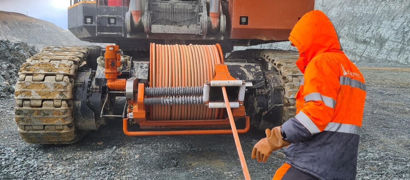
Modern electric excavators utilize sophisticated automated cable reeler systems. These motorized drum units actively sense cable tension and angle, adjusting reel speed in real-time to match machine movement.
Key technical characteristics of excavator reeling systems include:
Extended Working Radiuses: Standard automated excavator cable reelers are engineered to accommodate cable lengths ranging between 250 metres and 300 metres on a single drum layer, allowing broad machine travel without requiring manual cable repositioning.
Reduced Operational Hazards: Automatic payout and retrieval eliminate the need for ground personnel to manually handle live high-voltage cables near active digging faces, greatly improving site safety.
Protection Against Torsion: Excavators routinely execute multi-axis slewing movements. The cable structure must incorporate high torsional resistance to prevent outer sheath twisting and internal phase core displacement as the machine rotates relative to the trailing cable anchor point.
5. Conveyor Applications
Mobile conveyor systems, shiftable overland conveyors, and tripper cars operate over significantly longer distances than individual digging machines. As mining faces advance, mobile conveyor tail-ends and shiftable drive stations must relocate along pit benches to keep pace with material extraction.
Cable selection for moving conveyor infrastructure differs significantly from shovel applications:
Longer Travel Lengths: Conveyor reeling systems often must accommodate continuous travel lengths exceeding 500 metres, requiring larger reel drums and precise, low-tension payout management.
Intermittent vs. Continuous Cycling: While shovel cables experience near-constant motion, shiftable conveyor cables may remain stationary in a paid-out state for days or weeks before experiencing a major repositioning event.
Environmental Exposure: Stationary paid-out cables on conveyor runs spend extended periods resting directly on hot bench surfaces, pit roads, or dedicated cable tray paths. They require outer sheathing materials formulated with extreme ultraviolet stability and heat-aging resistance to survive prolonged Australian sun exposure without cracking or degrading.
6. Current Capacity as a Selection Factor
Selecting an appropriate conductor cross-section for a 6kV reeling cable begins with calculating the continuous continuous current carrying capacity, or ampacity. A cable must carry the full continuous operating current of the machine without exceeding the maximum allowable temperature limit of its insulation system—typically set at 90°C for high-grade Ethylene Propylene Rubber (EPR) compound formulations.
Calculating the continuous allowable current involves several crucial environmental and operational correction factors:
Ambient Temperature Adjustments
Standard international ampacity rating tables are based on a nominal ambient air temperature of 30°C. However, operational bench temperatures in Australian mining regions like the Pilbara, Kalgoorlie, or the Hunter Valley routinely exceed 40°C to 45°C in the shade, with radiant heat off rock surfaces raising local ground temperatures even higher.
If a cable is operated in a 45°C ambient environment, its baseline ampacity must be derated by applying thermal correction factors (often reducing rated current capacity by 12% to 20%). Failure to derate conductor capacity leads to accelerated insulation aging, dielectric breakdown, and premature cable failure.
Reel Derating and Multi-Layer Factors
When a reeling cable is spooled onto a storage drum, heat generated by the inner cable layers cannot easily dissipate into the surrounding atmosphere. As additional cable layers are wrapped over underlying turns, thermal trapping becomes severe.
Ampacity derating factors must be applied based on the number of cable layers on the drum:
Single Layer Spooling: Heat dissipation is relatively unimpeded, requiring minimal derating (typically a factor of 0.85 to 0.95 depending on drum design).
Two Layer Spooling: Derating factor drops significantly, often to approximately 0.65 to 0.70 of nominal free-air ampacity.
Three Layer Spooling: Derating factor drops to approximately 0.50 to 0.55.
Four Layer Spooling: Derating factor drops further to roughly 0.45, meaning the cable can safely carry less than half of its rated open-air current.
Engineers must ensure that the conductor cross-section is sized for the absolute worst-case operating scenario: full electrical load drawn while the majority of the cable remains wrapped on the drum in peak summer temperatures. Manufacturers like Feichun Cable engineer medium-voltage mining cables specifically using high-thermal-grade compounds to assist operators in optimizing current ratings under severe ambient conditions.
7. Voltage Drop Over Distance
Even when a chosen conductor cross-section satisfies thermal ampacity criteria, it must still be evaluated for terminal voltage drop. Long cable runs across expansive mine pits increase total phase resistance and inductive reactance. Excessive voltage drop reduces motor torque on the machine, causes excessive starter coil chatter, increases operational motor currents, and can trigger unwanted medium-voltage trip events.
Conceptual Math for Voltage Drop
In simple direct-current or basic resistive single-phase circuits, voltage drop is expressed as:
$$\Delta V = I \times R \times L$$
Where Delta V is the total voltage drop, I is the circuit current, R is the resistance per unit length, and L is the total circuit length.
Comprehensive Three-Phase Medium-Voltage Calculations
For heavy-duty three-phase alternating current medium-voltage systems supplying dynamic inductive loads (such as large squirrel-cage or wound-rotor induction motors driving hydraulic pumps and shovel hoists), calculation requires accounting for both AC resistance and inductive reactance:
$$\Delta V = \sqrt{3} \times I \times L \times (R \cdot \cos(\phi) + X \cdot \sin(\phi))$$
In this comprehensive equation:
$I$ represents the operating line current in Amperes.
$L$ represents the total cable route length in kilometres.
$R$ represents the AC conductor resistance at maximum operating temperature (90°C) in Ohms per kilometre.
$X$ represents the inductive reactance of the cable construction in Ohms per kilometre.
$\cos(\phi)$ is the operating power factor of the load, while $\sin(\phi)$ is the corresponding reactive power factor component.
In typical open-cut Australian installations, the maximum acceptable voltage drop under steady-state operating conditions is generally held between 3% and 5% of the nominal supply voltage (yielding a maximum allowable drop of 180V to 300V on a 6kV network). During heavy motor starting cycles, transient drops must usually remain within 10% to 12% to prevent contactors from opening or digital drive controls from faulting. If calculated voltage drop exceeds these thresholds, engineers must select a larger conductor cross-section (e.g., jumping from 50 square millimetres to 70 square millimetres) regardless of thermal ampacity compliance.
8. Mechanical Load and Reeling Stress
While electrical calculations dictate conductor size and insulation thickness, mechanical engineering determines whether a 6kV cable will survive past its first few months of service. Reeling cables operating on shovels and excavators are subjected to relentless dynamic mechanical stress.
Key physical forces include:
Tensile Stress
When a cable is pulled off a drum or dragged across pit floor gravel, high tensile pull acts directly on the internal assembly. Standard copper conductors have relatively low tensile limits under dynamic flexing. If pulling forces exceed maximum continuous allowances (typically 15 to 20 Newtons per square millimetre of total main conductor area), individual fine copper strands begin to stretch, neck down, and eventually snap, leading to localized hotspotting and internal open-circuit faults.
To prevent conductor stretch, advanced medium-voltage reeling cable designs incorporate central strength members made from aramid yarn (Kevlar) cores or high-tensile synthetic fiber braids embedded within the inner/outer sheath interface.
Torsional Shear and Twisting
When a mobile excavator rotates its upper superstructure, or when a cable is spooled onto a drum at an angle, the cable experiences severe torsional twisting forces. Torsion causes internal phase conductors to untwist or bunch up into "bird-caging" distortions, which puncture through phase insulation and cause catastrophic phase-to-phase short circuits.
Quality cable construction addresses torsion through counter-directional stranded conductor lay lengths and high-density, anti-torsional polyester or textile reinforcement braids firmly bonded between the inner and outer sheathing layers.
Bending Fatigue and Drum Cycling
Repeated bending over guide sheaves, fairleads, and reel drums stresses the insulation structure. Bending stress is directly related to the bending radius enforced by the handling equipment. Bending a cable tighter than its specified minimum bending radius causes micro-cracking in the insulation layers and breaks fine conductor strands.
9. Drum Capacity and Reel Selection
Calculating required reeling cable drum capacity involves balancing spatial limits on the mining machine against the mechanical physical properties of the cable structure. Selecting a drum unit is never a simple matter of choosing a reel that holds a specific length of wire; it requires evaluating physical cable dimensions, minimum bending radiuses, and dynamic operating allowances.
Key calculation factors include:
Cable Outer Diameter and Weight
The overall outer diameter of a 6kV medium-voltage cable is influenced by phase conductor size, semiconductor screen layers, primary rubber insulation thickness, earth conductor arrangements, and outer sheathing walls. A larger outer diameter exponentially increases the required drum flange diameter and drum barrel width. Furthermore, the total weight of the spooled cable directly impacts the required motor torque of the reel drive unit.
Minimum Bending Radius Standards
To prevent mechanical damage to internal phase components, industry standards mandate strict minimum bending radius limits for dynamic medium-voltage reeling applications:
For Dynamic Reeling Operations: Minimum bending radius is typically specified as 10 to 12 times the overall outer cable diameter.
For Guided S-Bend Route Sheaves: Minimum bending radius often increases to 12 to 15 times the outer cable diameter.
If a 6kV cable has an outer diameter of 60 millimetres, the minimum allowable drum barrel diameter must be at least 1.2 metres (20 times the cable radius, or 10 times the diameter) to avoid premature mechanical degradation.
Dead Turns and Reserve Capacity
Safety standards require that a cable reel must never be unwound completely during normal operation. A minimum of 2 to 3 "dead turns" must always remain on the drum barrel when the machine reaches its maximum operational displacement. These reserve turns serve as a mechanical anchor, ensuring that pulling tension exerted by the machine is absorbed directly by the drum structure rather than transferred to the fragile electrical collector ring or slip-ring assembly inside the hub.
Calculating correct reeling cable drum capacity requires integrating the cable's exact outer diameter, bending radius tolerances, dead-turn reserves, and machine travel range.
10. Construction Features to Look For
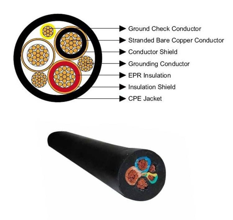
To withstand the severe conditions found in Australian mining operations, a 6kV medium-voltage reeling cable requires a precisely engineered layered structure. Each component serves a distinct electrical or mechanical protection purpose.
Flexible Conductors
Phase conductors must utilize high-flexibility Class 5 or Class 6 fine-stranded tinned copper wires. Tinned copper provides superior corrosion resistance against moisture and chemical atmospheric exposure compared to bare copper. The strands are wound in short lay lengths to maximize flexibility and minimize internal friction during repeated bending cycles.
Insulation and Semiconductor Shielding
Medium-voltage cables operating at 6kV require sophisticated electric field control:
Conductor Screen: A thin layer of extruded semi-conductive compound applied directly over the stranded copper conductor to smooth out electrical field stress points caused by individual outer strands.
Primary Insulation: High-grade Ethylene Propylene Rubber (EPR) insulation provides exceptional dielectric strength, thermal resistance up to 90°C continuous operating temperatures, and excellent mechanical flexibility at both low and elevated temperatures.
Insulation Screen: A second extruded semi-conductive layer applied over the EPR insulation, covered by a tinned copper braid or composite metallic tape screen. This ensures a uniform radial electric field within each phase core, preventing localized electrical stress concentrations that lead to internal partial discharge and dielectric breakdown.
Earth Core Distribution and Pilot Wires
To meet stringent mining electrical safety regulations (such as Australian AS/NZS standards covering trailing and reeling cables), earth conductors are split symmetrically into three equal control cores positioned in the outer interstices between the three main phase cores. Splitting the earth core provides symmetrical physical balance, reduces total cable diameter, and minimizes inductive coupling noise. Central pilot cores are often included to maintain continuous earth-monitoring pilot loops, instantly tripping substation circuit breakers if ground continuity is broken.
Heavy-Duty Outer Sheathing
The outer jacket serves as the main barrier against harsh physical environments. High-performance mining cables utilize heavy-duty synthetic rubber compounds, such as Chlorinated Polyethylene (CPE), Polyurethane (TPU), or polychloroprene (PCP):
Abrasion Resistance: Protects internal cores when dragged over sharp, crushed iron ore or basalt rocks.
Tear and Cut Resistance: Prevents deep structural gouges caused by mechanical impacts or accidental vehicle run-overs.
Chemical and Oil Resistance: Prevents degradation from hydraulic fluid leaks and grease exposure around machine carbody frames.
UV and Flame Retardancy: High chemical resistance ensures the cable does not degrade under intense Australian ultraviolet solar radiation and resists flame propagation in the event of an external fire.
Manufacturers such as Feichun Cable engineer customized medium-voltage mining reeling cables with specialized heavy-duty outer sheaths and reinforced internal assemblies tailored to survive these extreme physical demands.
11. Safety and Operational Benefits
Investing in high-quality 6kV medium-voltage reeling cable systems yields substantial operational and safety advantages across open-cut site operations.
Eliminating Manual Handling Hazards
Manual trailing cable handling is historically one of the highest-risk activities on a mine site. Moving heavy live electrical cables manually or with tractors exposes ground crews to severe crush injuries, trip hazards, physical fatigue, and potential electrical flashover dangers. Automated motor-driven reel systems allow heavy excavators and shovels to pay out and retrieve cable automatically without requiring ground personnel near the active machine track path.
Continuous Tension Control and Monitoring
Modern cable reeler units utilize closed-loop electronic torque control paired with integrated tension-sensing load cells. These systems continuously monitor line pull and payout angles:
Over-Tension Protection: If the cable gets caught on a rock or pit bench obstruction, the reel system instantly detects the sudden tension spike and halts machine travel or alarms the operator, preventing catastrophic tension tears.
Under-Tension / Slack Protection: Prevents the cable from becoming loose and drooping into machine track assemblies or getting run over by the excavator's own tracks.
Maximizing Machine Uptime
Unplanned electrical failures directly stall production schedules, causing costly equipment downtime. Utilizing robust 6kV reeling cables engineered specifically for extreme mechanical stress and high ambient thermal loads dramatically reduces unexpected insulation blowouts, core fractures, and earth-fault tripping events. High reliability translates directly into higher tonnage moved per shift and lower long-term total cost of ownership.
12. Recommended Conclusion
Selecting the right 6kV medium-voltage reeling cable for heavy mining equipment requires balancing electrical performance, mechanical durability, dynamic drum capacity, and environmental resilience.
Operating at 6kV medium voltage provides a fundamental physical advantage over low-voltage power distribution: dramatically reducing continuous operating current allowed for smaller conductor cross-sections, manageable cable overall diameters, reduced thermal resistive losses, and improved mechanical handleability on machine reels.
However, selecting a cable based on voltage class and basic ampacity alone is insufficient. Mine operators, site engineers, and electrical procurement specialists must thoroughly evaluate:
Environmental Thermal Derating: Factoring in high ambient summer temperatures and multi-layer reel thermal trapping.
Voltage Drop Checks: Ensuring terminal supply voltage remains stable across long operating distances under peak motor starting loads.
Mechanical Fatigue Protection: Verifying that internal tensile members, anti-torsion braids, and core constructions can withstand repeated dynamic spooling cycles and harsh ground drag.
Drum and Reel Compatibility: Matching cable outer diameter and minimum bending radiuses to storage drum geometries and guide sheave configurations.
When engineered with high-grade EPR insulation, flexible Class 5/6 tinned copper stranding, symmetrical earth core distribution, and high-abrasion UV-resistant outer sheathing, a 6kV reeling cable provides a safe, efficient, and reliable power umbilical. By aligning cable physical specifications with actual site conditions, Australian open-cut operations can protect site personnel, extend heavy equipment uptime, and achieve long-term material handling productivity.
How to Reach Us
Get in Touch
SiteMap
Product Catalogue
Festoon Cable
Shore Power Cable




Scan to add us on WeChat