
Cable Solutions for Container Spreader Systems
Discover how to select the right container spreader cable for STS, RTG, and RMG cranes. Learn about flexing, torsion, marine environments, and reliable cable solutions for modern port operations.
hongjing.Wang@Feichun
6/16/202630 min read

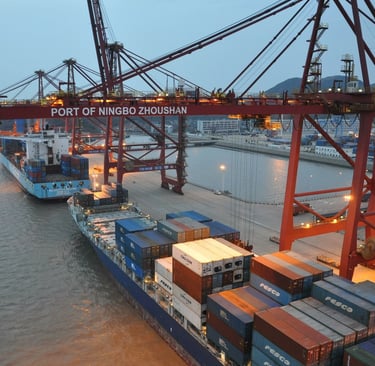
Container terminals across Australia run on tight margins and even tighter schedules. From Port Botany's round-the-clock vessel calls to the steady throughput at the Port of Brisbane and Fremantle Port's exposure to relentless Indian Ocean weather, the equipment that moves boxes from ship to shore and back never really gets a quiet moment. At the sharp end of all that activity sits the spreader — the component that actually grabs the container — and quietly threaded through every spreader is a cable that has to survive conditions most cables would never tolerate.
This article looks closely at how spreader cables earn their keep, why ordinary flexible cables let crews down, and what to look for when you're specifying a cable that needs to last. It's written for the maintenance engineers, electrical supervisors, procurement officers, and terminal managers who deal with cable failures as a real operational cost rather than a line item on a datasheet. If you've ever stood under a gantry crane at three in the morning waiting on a cable replacement while a ship racks up berthing charges, this one's for you.
Choosing the Right Flexible Cable for STS, RTG, and RMG Crane Spreaders
Why Spreader Cables Deserve a Second Look
Most people working around container handling equipment take the cabling for granted. It's tucked into festoon systems, wound onto reeling drums, or fed through energy chains, doing its job out of sight until the moment it stops. And when a spreader cable fails, it rarely fails politely. You get intermittent twistlock signals, dropped communication to the sensors, or a dead camera feed right when the operator needs it most. In the worst cases the cable simply gives up mid-shift, and a crane that costs thousands of dollars an hour to run sits idle while someone finds the spare, pulls the old cable, and re-terminates everything.
The frustrating part is that a large share of these failures trace back to a single decision made long before the cable ever went into service: somebody chose a general-purpose flexible cable when the application demanded a purpose-built crane cable. On paper the two looked similar. In the field they behave nothing alike.
Container spreaders are among the most mechanically demanding environments any cable will ever face. The spreader doesn't just bend — it telescopes, twists, corrects skew, rotates, and lifts, often several of those at once, thousands of times a day, for years. A cable that's merely "flexible" in the catalogue sense will survive a domestic appliance or a light industrial machine quite happily. Drop it into a spreader and it starts dying from the first shift.
So before getting into specifics, it's worth being honest about the scale of the demand. We're talking about a cable that has to flex continuously, resist twisting forces that would unravel an ordinary conductor, shrug off salt spray and UV, tolerate Australian deck temperatures in summer, and keep its electrical performance rock-steady through all of it. That's a tall order, and it explains why crane-specific cables exist as a distinct category in the first place.
Understanding How Container Spreader Systems Work
To specify the right cable, you first need a clear picture of what the spreader is actually doing to it. A container spreader is the rectangular steel frame that lowers onto a container, aligns itself, locks on via twistlocks, lifts, and releases. It sounds straightforward, but the reality involves several distinct movements happening in sequence and sometimes simultaneously — and each one places a different kind of stress on the cable.
Telescoping Movement
Containers come in standard lengths — 20 foot, 40 foot, 45 foot — and a single spreader has to handle all of them. It does this by telescoping: the frame physically extends and retracts to match the box. Every time the spreader changes size, the cable feeding power and signals to the moving section gets dragged along with it.
What this means for the cable is repeated, continuous bending. Not a one-off bend, but a flex cycle that happens on virtually every lift. Over a year that adds up to hundreds of thousands of bending events. A cable specified for this duty needs genuine continuous-flex capability — fine-stranded conductors that distribute the bending stress across many thin wires rather than concentrating it on a few thick ones, and a flexible jacket that moves with the conductor instead of fighting it. The flex life rating matters enormously here, because telescoping is relentless and it never stops for the life of the spreader.
Twistlock Operation
Once the spreader is aligned over the container, the twistlocks rotate into the corner castings and lock on. These are electrically actuated and monitored, which means the cable carries the control signals that command the locks and the feedback signals that confirm they've engaged. Getting this wrong has obvious safety implications — you do not want a container released because a control signal dropped out.
The cable requirement here is less about brute mechanical strength and more about signal integrity under movement and vibration. You need stable, reliable transmission through a multi-core construction, with cores that keep their electrical characteristics even as the cable flexes and the whole assembly shakes from the crane's operation. A cable that develops intermittent faults in its control cores is worse than useless, because intermittent faults are maddening to diagnose and erode trust in the whole system.
Skew Correction
When a spreader lifts an unevenly loaded container, or when wind catches it, the load can sit crooked. Modern spreaders correct for this automatically, adjusting alignment during the lift to keep the container level. From the cable's point of view, skew correction introduces side-pulling forces — lateral loads that try to drag the cable sideways rather than simply bending it.
This calls for a cable with mechanical stability and resistance to those transverse forces. A flexible construction is essential, but it has to be a controlled flexibility, where the cable can move without the cores shifting around inside the jacket or the sheath deforming permanently. Cheap cables tend to develop a kind of internal sloppiness under repeated side loading, and once the internal structure loosens, the failure clock starts ticking faster.
Rotation Movement
Many spreaders rotate to fine-tune container positioning, particularly in tight stacking situations or when aligning with a precise landing point. Rotation is, frankly, the cruelest thing you can do to a cable, because it introduces torsion — twisting along the cable's length.
Torsion is fundamentally different from bending, and it's where most ordinary cables fail catastrophically. When you twist a cable repeatedly, the conductors inside want to unwind or wind tighter depending on the direction, and over time this accumulated twisting stress causes the conductor strands to migrate, bunch up, and eventually break. The jacket can deform into a spiral, and in severe cases the conductors push outward in what's called "bird-caging" — the strands splay out like the bars of a birdcage and the cable is finished.
A cable built for rotation needs genuine anti-torsion construction. This usually means a balanced, symmetrical core arrangement so that twisting forces distribute evenly, combined with a reinforcing element — typically a braided layer of polyester threads — that absorbs and resists the torsional load before it reaches the conductors. The reeling and drum cables discussed later in this article are specifically rated for defined twist limits, expressed in degrees per metre, precisely because torsion is such a critical failure mode.
Different Spreader Systems and Their Cable Challenges
Not every crane is the same, and the type of crane shapes the cable challenge in important ways. Australian terminals run all three major gantry types, often side by side, and each one stresses cables differently.
STS Crane Spreaders
Ship-to-Shore cranes are the towering structures you see along the wharf, reaching out over berthed vessels to lift containers directly from the ship's hold or deck. They are the highest-profile, highest-pressure machines in the terminal, and they operate right at the waterline where the environment is at its most hostile.
The defining challenge for STS spreader cables is the coastal environment. These cables live in salt spray, soak up UV radiation through the long Australian summer, sit in high humidity, and face the constant low-grade chemical assault of a marine atmosphere. Salt and moisture work their way into any weakness in the jacket and corrode metallic components; UV breaks down jacket compounds that weren't formulated to resist it, causing them to harden, crack, and eventually fail.
So an STS spreader cable has to combine the mechanical toughness any spreader demands with serious environmental credentials: a UV-resistant outer sheath, genuine resistance to saltwater and the corrosion it drives, high bending endurance for the constant telescoping and reeving, and dependable signal transmission for the twistlock and sensor systems. The jacket compound matters as much as the conductor here, because a mechanically perfect cable with a sheath that crumbles in two summers hasn't actually solved your problem.
RTG Crane Spreaders
Rubber-Tyred Gantry cranes work the container yard rather than the wharf, stacking and retrieving boxes in the storage areas. Unlike the fixed STS cranes, RTGs are mobile — they drive around the yard on their rubber tyres, repositioning between stacks and rows.
This mobility changes the cable picture. The challenges here are frequent movement, variable cable routing as the crane shifts position, repetitive bending cycles as the spreader works through its stacking operations, and the mechanical vibration that comes from a large machine driving across the yard surface. The cable isn't just flexing at the spreader; the whole power and control feed has to tolerate the crane's travel.
The cable characteristics that suit RTG duty are excellent all-round flexibility, strong abrasion resistance for the times the cable contacts guides and structures, a long bending life to handle the high cycle count, and a robust jacket that can take knocks and rubbing without giving up. RTG cables tend to live a harder, more varied life than their STS counterparts, even if they're not as constantly drenched in salt spray, and the jacket construction has to reflect that.
RMG Crane Spreaders
Rail-Mounted Gantry cranes run on fixed rails and are increasingly the backbone of automated container terminals. Because they're guided by rails, their movement paths are far more controlled and predictable than an RTG's — but don't mistake controlled for gentle.
Automated RMG systems run enormous numbers of operating cycles. They don't take smoko, they don't knock off at the end of a shift, and in a fully automated terminal they can run virtually continuously. The dominant challenge for RMG spreader cables is therefore long-term fatigue: the slow accumulation of stress from millions of cycles over the cable's service life. Even small per-cycle stresses add up when you multiply them by that kind of cycle count.
What you want in an RMG spreader cable is rock-steady electrical performance that doesn't drift over time, a genuinely high cycle life rating, consistent and predictable mechanical behaviour so the cable doesn't surprise you, and the kind of reliability that supports planned maintenance intervals rather than unplanned breakdowns. In an automated terminal, an unplanned cable failure can stall a whole automated sequence, so predictability is worth a great deal.
Why Standard Cables Often Fail in Spreader Applications
It's worth dwelling on the specific ways cables die in spreader service, because understanding the failure modes is the key to avoiding them. Almost every premature failure falls into one of a handful of categories, and almost all of them come back to using a general-purpose flexible cable where a crane-specific design was needed.
Conductor Fatigue
This is the slow killer. Every time a conductor bends, the copper strands on the outside of the bend stretch slightly and the strands on the inside compress. Do that a few times and nothing happens. Do it hundreds of thousands of times and the fine copper strands start to work-harden and break, one at a time.
The insidious thing about conductor fatigue is how it presents. You don't get a clean failure. Instead you get intermittent signals as broken strands make and lose contact, communication faults that come and go, and downtime that seems to strike at random. Crews chase these faults for hours because the cable tests fine when it's sitting still and only misbehaves under movement. The defence against conductor fatigue is fine, finely stranded conductors — the more strands and the thinner each one, the more bending the conductor can absorb before fatigue sets in. This is why the cables built for this duty use very finely stranded, Class 5 tinned copper conductors rather than the coarser stranding you'd find in a standard flexible cable.
Torsional Damage
We touched on this under rotation, but it deserves its own treatment because it's so destructive. Torsion attacks a cable in ways bending never does. The visible symptoms are telling: a spiral deformation in the jacket where the whole cable has taken a permanent twist, cores that have twisted around inside, and in the terminal stage, bird-caging where the conductor strands splay outward and lose all their structure.
Once you see bird-caging, the cable is gone — there's no recovering it. The only real defence is to specify a cable with a proper anti-torsion design from the outset: a balanced, symmetrical core layout and a reinforcing braid that resists the twisting load. Cables rated with explicit torsional limits, such as plus or minus a defined number of degrees per metre, are telling you they've been engineered and tested specifically to survive this. A cable with no torsion rating has no business in a rotating spreader application.
Jacket Abrasion
Spreader cables don't move through empty space. They run over rollers, past guides, along cable trays, and sometimes against the metallic structure of the crane itself. Every contact point is a place where the jacket gets rubbed, and over time that rubbing wears the sheath away.
The signs are straightforward to spot if you're looking: visible wear flats on the outer sheath, cracking where the jacket has thinned and lost flexibility, and a gradual loss of the environmental protection the jacket is supposed to provide. The danger is that once the outer sheath is breached, salt, moisture, and oil get into the cable's interior and accelerate every other failure mode. A robust, abrasion-resistant outer sheath — typically a high-grade rubber compound formulated specifically for tear and abrasion resistance — is the first line of defence, and it's one of the clearest differences between a real crane cable and a generic flexible one.
Environmental Degradation
Australian ports are tough on materials, full stop. The combination of salt spray, intense UV, high deck temperatures in summer, and humidity cycling works steadily to break down any material that wasn't designed for it. Salt corrodes, UV photo-degrades polymer chains, heat accelerates every chemical reaction, and humidity drives moisture ingress.
A jacket compound that's fine in a temperate indoor factory can age dramatically faster in a coastal port. The result is premature hardening, cracking, and loss of flexibility — and a stiff, cracked cable fails mechanically far sooner than a supple one. This is why the environmental ratings of a spreader cable matter so much: resistance to ozone, UV, and moisture isn't a luxury feature in an Australian port, it's a baseline requirement. Cables rated for unrestricted outdoor use, with explicit ozone, UV, and water resistance, are designed to hold their properties through exactly the conditions our ports throw at them.
Cable Types Used in Container Spreader Systems
Container handling systems use several distinct categories of cable, each matched to a particular way of routing power and signals to a moving spreader. Knowing which category fits your application is the first step in narrowing down a specification.
Festoon Cables
Festoon systems are the looping cable arrangements you see hung from trolleys on a track, gathering and spreading like an accordion as the trolley travels. They're a classic, reliable way to feed a moving element, and they show up on trolley systems, on moving spreaders, and on horizontal travel systems throughout container handling equipment.
The defining demand on a festoon cable is bending. As the festoon gathers and spreads, the cable bends repeatedly at the loops, so the cable needs excellent bending performance and a long flex life above all else. The cables suited to this duty are designed to flex smoothly and repeatedly without the cores binding or the jacket fatiguing. A festoon cable that's specified correctly will outlast a generic flexible cable many times over in the same application, simply because it was built for the one thing festoon service demands most: reliable, repeated bending.
Among the cables that suit festoon and horizontal travel duty are the heavy-duty rubber-sheathed flexible designs built for mobile connections under severe mechanical stress. These typically use Class 5 finely stranded tinned copper conductors, rubber insulation, and a tough rubber outer sheath, with core counts ranging from a few power cores up to multi-core control configurations. The flat festoon variants are particularly suited to trolley-mounted festoon trolleys where a flat profile sits neatly in the carriers.
Reeling Cables
Reeling cables are a different animal. Instead of looping like a festoon, a reeling cable winds onto and off a motorised drum as the crane or trolley moves. This is the arrangement of choice for longer travel distances and for vertical lifting, and it's standard on cable drum systems, vertical lifting systems, and heavy-duty crane operations.
Drum reeling places a particular combination of stresses on the cable. As the cable winds onto the drum, it's under tension; as layers build up, the inner layers carry the load of the outer ones; and the constant winding and unwinding introduces both bending and, depending on the system geometry, torsion. A reeling cable therefore needs high tensile strength to survive the pulling loads, anti-torsion construction to handle the twisting, and stable winding behaviour so the cable lays neatly on the drum without snarling.
The cables built for this duty show their pedigree in their construction. A typical heavy-duty drum reeling cable uses Class 5 tinned copper conductors for flexibility and corrosion resistance, a rubber insulation system, a polyester braid as the anti-twisting element, and a tough rubber outer sheath. These cables are rated with explicit twist limits and travel speeds — for instance, twist limits around 50 degrees per metre and travel speeds up to roughly 100 metres per minute for the lower-voltage power-and-signalling designs — which tells you they've been engineered and tested specifically for the demands of drum service. The medium voltage reeling cables go further still, with reinforced anti-torsion braids vulcanised in a bond between inner and outer sheath layers, sandwich-structure sheaths that combine flexibility with robustness, and torsional ratings that allow churning over rollers and multiple directional changes into different planes. These are the cables you reach for when the mechanical stresses move from severe into extreme — fast-moving container cranes, high travel speeds, and dynamic tensile loads.
Spreader Control Cables
Where festoon and reeling cables are mostly about delivering power and surviving movement, spreader control cables are about carrying lots of signals reliably. Modern spreaders are bristling with sensors, cameras, and twistlock actuators, and all of that needs wiring back to the control system. Control cables handle twistlock control, sensor systems, camera systems, and data transmission.
The defining feature of a spreader control cable is its high core count. Common configurations run to 24, 36, or even 48 cores of fine cross-section conductor — enough to carry all the discrete signals a busy spreader generates. Despite the high core count, these cables still have to flex, because they ride along with the spreader, so they pair a multi-core design with the same flexible construction principles as the power cables: finely stranded conductors, a flexible rubber system, and reliable signal integrity across every core.
The heavy-duty multi-core flexible cables suited to this role offer core counts well into the dozens at 1.5 and 2.5 square millimetre cross-sections, with the higher core-count versions often including a central filler for stability and consistent geometry. Because a single dropped core in a control cable can disable a sensor or a camera, the consistency of these cables across all their cores is just as important as the bulk mechanical properties.
Reading the Technical Specifications That Matter
When you're comparing spreader cables, the datasheets can feel like a wall of numbers. But a handful of parameters carry most of the decision, and learning to read them quickly saves a lot of grief. Here's how to think about the ones that matter most, drawn from the kinds of figures real crane cables publish.
Start with the voltage rating. Power reeling and control cables for spreaders commonly sit at 0.6/1 kV for the low-voltage power-and-signalling designs, where the conductor-to-earth and conductor-to-conductor ratings are 600 and 1000 volts respectively, with a test voltage well above that to confirm insulation integrity. Where the crane feeds medium voltage power down a reeling cable — common on larger STS cranes — you step up into a whole family of ratings, from 1.8/3 kV through 3.6/6 kV, 6/10 kV, 8.7/15 kV, and on to 12/20 kV and beyond. The medium voltage reeling cables carry correspondingly higher test voltages and use sophisticated field-control layers to manage the electrical stress. Match the rating to your system; there's no prize for over-specifying voltage, but under-specifying it is dangerous.
Next, look at the temperature rating, and notice that good crane cables quote two figures: one for fixed installation and one for flexing. A typical heavy-duty design might be rated for fixed use from minus 40 to plus 90 degrees Celsius and flexing use from minus 25 to plus 90 degrees. That upper figure of 90 degrees at the conductor matters in an Australian summer, where a black cable sitting in full sun on a steel deck can get genuinely hot. The medium voltage reeling cables push the fixed-installation ambient range even wider, down to minus 50 degrees for the most demanding climates, while still holding a 90 degree conductor temperature.
The twist limit, quoted in degrees per metre, is the parameter that separates real anti-torsion cables from pretenders. A power-and-signalling reeling cable rated at 50 degrees per metre is telling you exactly how much twist it can take per metre of length, repeatedly, without damage. Medium voltage reeling cables built for the harshest churning-over-rollers duty quote tighter torsional figures — around plus or minus 25 degrees per metre — reflecting the more demanding service and the heavier construction. If a cable has no twist rating at all and your spreader rotates, that's a red flag.
Travel speed matters for reeling applications. A figure such as up to 100 metres per minute tells you how fast the drum can wind the cable without overstressing it. The heavy-duty medium voltage reeling cables go much faster — gantry reeling operation with essentially no restriction up to very high speeds, with a recommendation to consult the manufacturer beyond around 240 metres per minute. Match this to your crane's actual travel speed with margin to spare.
The minimum bending radius is a deceptively important number, because installers ignore it at their peril. It's usually expressed as a multiple of the cable's outer diameter, and it differs depending on whether the cable is fixed, moving freely, running on drums, or passing over deflection pulleys. A typical heavy-duty cable might want a fixed-installation radius of around four times the outer diameter and a free-moving radius of around five times, with larger multiples — say seven and a half times — required on deflection pulleys where the bending is more severe. Bend a cable tighter than its rated radius and you've pre-loaded it for an early failure no matter how good the construction is.
Then there's tensile load and maximum permissible tensile force. Reeling cables carry their own weight plus the dynamic loads of winding, and the published maximum tensile loads — running from a few hundred newtons on small control cables up to many thousands of newtons on heavy power cables — tell you how hard the system can pull on the cable before damage. The medium voltage reeling cables distinguish between a permissible steady tensile force and a higher dynamic tensile force allowed during acceleration, which is exactly the distinction a reeling system needs because the worst loads happen when the drum accelerates.
Finally, the conductor cross-section and current carrying capacity size the cable for its electrical load. Cross-sections from 1.5 square millimetres for control cores up to 240 or 300 square millimetres for heavy power conductors cover the range you'll meet in spreader systems. Crucially, the current rating for a reeled cable is much lower than for the same cable laid in open air, because a cable wound in layers on a drum can't shed heat the way an open cable can. Good datasheets publish separate ratings for free air, for laying on the floor, and for reeling in one, two, three or more layers — and the reeled figures drop sharply as the layer count rises. If you size a reeling cable from its free-air rating, you'll overheat it. Always use the reeled figure for the actual number of layers on your drum, and apply the de-rating factors for ambient temperature on top.
Environmental Challenges in Australian Container Ports
Australia's major container ports operate in some of the more demanding coastal environments in the developed world, and the cable implications are real. Port Botany in Sydney, the Port of Brisbane, and Fremantle Port in Western Australia all sit hard against the ocean, and all of them subject their crane cables to a punishing cocktail of environmental stresses.
Salt Spray
Coastal air carries salt, and salt is corrosive. Fine salt spray settles on every surface and works its way into any gap in a cable's protection. It corrodes exposed metallic components, attacks terminations, and — if it reaches the conductors through a damaged jacket — degrades them from within. The tinned copper conductors used in good crane cables are chosen partly for this reason: the tin coating gives the copper a meaningful additional layer of corrosion protection compared with bare copper, which matters enormously in a salt-laden atmosphere.
UV Exposure
The Australian sun is no joke, and UV radiation is one of the great destroyers of polymer materials. UV breaks down the molecular chains in jacket compounds that weren't formulated to resist it, causing the sheath to harden, lose flexibility, discolour, and eventually crack. A cracked jacket is an open door for moisture and salt. Cables specified for outdoor crane duty use jacket compounds explicitly formulated and rated for UV resistance, which is why their published environmental specifications call out UV resistance specifically rather than leaving it to chance.
Heat
Beyond the conductor heating that comes from carrying current, Australian deck temperatures add a substantial external thermal load. A dark-jacketed cable lying on a steel structure in full summer sun can reach temperatures well above ambient air, and that heat accelerates every degradation process — chemical, mechanical, and electrical. This is precisely why the upper temperature ratings of crane cables, typically 90 degrees at the conductor, are so important, and why you must apply ambient temperature de-rating when sizing the cable. A cable that's comfortably rated for a temperate climate can be marginal in a Western Australian summer if you don't account for the heat properly.
Marine Humidity
High, cycling humidity is the quiet background stress in any coastal port. Moisture promotes long-term material degradation, drives corrosion when combined with salt, and can penetrate cables through any breach in the jacket. Good crane cables include water resistance in their specifications — some medium voltage designs even incorporate a dedicated water barrier layer within the sheath system — precisely because moisture management is a long-term reliability issue, not a one-off event.
Taken together, these factors mean a spreader cable for an Australian port should bring a complete environmental package to the table: UV resistance, ozone resistance, salt spray resistance, oil resistance, and proven long-term flex durability. Any one of these missing is a weak link, and in a coastal port the environment will find the weak link.
Selecting the Right Cable for Container Spreader Applications
Pulling all of this together, choosing a spreader cable comes down to working systematically through three areas: mechanical performance, environmental resistance, and operational reliability. Getting all three right is what separates a cable that lasts from one that becomes a recurring maintenance headache.
Mechanical Performance
This is the foundation. Confirm the minimum bending radius suits your installation geometry — fixed, free-moving, on drums, and over pulleys, each as applicable — and never design an installation that bends the cable tighter than its rating. Check the flexing cycle life and make sure it comfortably exceeds the cycle count your spreader will rack up over its planned service life, with margin for the unexpected. Verify the tensile strength against the real pulling loads in your reeling or festoon system, remembering to account for dynamic loads during acceleration, not just steady-state loads. And for any rotating application, insist on a published torsion resistance figure and confirm it covers the twisting your spreader actually imposes.
Environmental Resistance
In an Australian port this is not optional. Require UV resistance as a baseline. Require salt spray resistance given the coastal exposure. Require oil resistance, because oil and grease are everywhere on crane equipment and a cable that swells or degrades on contact with oil won't last. Require moisture resistance for the humidity cycling. The good news is that purpose-built crane cables generally bundle all of these together, because the people who design them know the environments these cables go into. The cables described in this article carry exactly this profile: rated for unrestricted outdoor use, resistant to ozone, UV, and moisture, with oil resistance tested to recognised standards.
Operational Reliability
Finally, think about the cable as part of a running operation rather than a component in isolation. Stable signal transmission keeps your twistlocks, sensors, and cameras honest. A long service life reduces how often you have to interrupt operations to replace cable. Predictable behaviour supports planned maintenance, which is always cheaper and less disruptive than reacting to failures. And lower maintenance costs over the life of the cable frequently more than offset a higher purchase price — a point worth making to whoever signs off the purchase order. The cheapest cable on the day of purchase is very often the most expensive cable over five years once you count the downtime, the replacement labour, and the knock-on costs of a stalled crane.
A Practical Word on Total Cost
It's tempting, especially under procurement pressure, to treat cable as a commodity and buy on price. Resist that temptation for spreader applications. The purchase price of a spreader cable is a small fraction of what a single avoidable failure costs once you add up the lost crane hours, the overtime to effect the repair, the spare parts inventory you have to carry to cover the risk, and — at the worst end — the berthing and schedule penalties when a ship is held up.
A purpose-built crane cable typically costs more upfront than a general-purpose flexible cable. It also typically lasts several times as long in the same application, because it was engineered for exactly the stresses the spreader imposes. When you work the numbers on a cost-per-operating-hour or cost-per-year basis rather than cost-per-metre at purchase, the purpose-built cable almost always wins, and usually wins comfortably. That's the case worth making internally when you're justifying the specification.
Matching Cable Families to Spreader Functions
To make this concrete, it helps to map the cable families back onto the spreader functions they serve, because in practice a single spreader installation often uses several cable types together.
For the power feed to a reeling-fed spreader or trolley, you want a reeling cable with strong tensile strength, a published twist limit, and a current rating calculated for the actual number of drum layers. Where the crane runs medium voltage power down to the spreader area, the medium voltage reeling cables with their anti-torsion braids, sandwich sheaths, and field-control layers are the appropriate choice, sized to the relevant voltage rating from the available family.
For the horizontal travel and festoon-fed sections, a heavy-duty rubber-sheathed flexible cable built for festoon duty gives you the bending performance and flex life that looping festoon service demands. The flat festoon variants suit trolley carriers particularly well.
For the twistlock, sensor, and camera control wiring, a high-core-count flexible control cable — running to 24, 36, or 48 cores of fine cross-section — carries all the discrete signals reliably while still flexing along with the spreader. Where the core count climbs, look for designs with a central filler for geometric stability.
In every case, the unifying requirements are the same: finely stranded tinned copper conductors for flex life and corrosion resistance, a rubber insulation and sheath system formulated for the marine environment, a polyester anti-torsion braid where twisting is in play, and a published, tested set of mechanical and environmental ratings you can check against your application. When a cable brings all of that, it's earned its place under the gantry.
Construction Details That Separate Good Cables From Adequate Ones
It's one thing to read a datasheet and another to understand why a cable is built the way it is. The internal construction of a spreader cable is where the engineering really lives, and a maintenance engineer who understands the construction will make far better specification and troubleshooting decisions than one who only reads the headline numbers. Let's walk through the layers of a typical heavy-duty crane cable from the centre outwards.
The Conductor
Everything starts at the conductor. In spreader applications, the conductor is invariably a finely stranded design — Class 5 by the common stranding classifications, or finer still in the most demanding medium voltage reeling cables. The reason is simple physics. When you bend a conductor, the strands on the outer radius stretch and the strands on the inner radius compress. The thinner each individual strand, the smaller that strain is, and the more bending cycles the conductor survives before fatigue cracks appear. A conductor made of a few thick strands fails quickly under flexing; a conductor made of hundreds of fine strands keeps going for an enormous number of cycles.
The choice of tinned rather than bare copper is equally deliberate. Tin plating on each strand resists the corrosion that salt-laden coastal air drives, and it also makes the conductor easier to terminate reliably over the cable's life. In a port environment, the corrosion resistance alone justifies the choice; a bare copper conductor exposed to moisture through even a small jacket breach will corrode and lose conductivity far faster than a tinned one. The medium voltage reeling cables take this further with electrolytic copper, very finely stranded to the finest stranding classes, because at medium voltage the consequences of conductor degradation are more serious and the mechanical demands higher.
The Insulation
Around each conductor sits the insulation, and for crane service this is almost always a rubber-based compound — commonly an ethylene propylene rubber formulation, or EPR. EPR is chosen over the PVC you'd find in cheaper cables for several reasons that all matter in this application. It stays flexible across a wide temperature range, including the cold end that matters in southern winters and the hot end that matters on a summer deck. It resists ozone and weathering. And it holds its electrical properties under repeated flexing far better than rigid insulation compounds.
In medium voltage reeling cables the insulation system becomes considerably more sophisticated, using high-grade special EPR compounds engineered for improved mechanical and electrical characteristics. At these voltages the cable also needs electrical field control — semiconductive layers inside and outside the insulation that manage the electrical stress and keep the field uniform. A clever feature of the better designs is a field-control layer that can be stripped off cleanly when cold, which dramatically simplifies the job of preparing and terminating the cable in the field. Anyone who has tried to terminate a medium voltage cable in awkward conditions will appreciate why easy stripping is a genuine selling point rather than a marketing flourish.
The Core Arrangement
How the cores are arranged inside the cable matters more than you might expect, particularly for torsion resistance. A symmetrical, balanced arrangement — where the cores are laid up evenly around the cable's centre — distributes twisting forces uniformly when the cable is subjected to torsion. An unbalanced arrangement concentrates stress and fails sooner. The best medium voltage reeling cables use a three-core design with the earth conductor split into parts and tucked into the spaces between the main cores, which both balances the construction and makes efficient use of the internal space. This symmetry also has an electrical benefit: it produces a very low interference level, which matters when the cable runs alongside sensitive control and signal wiring.
The Inner Sheath and Anti-Torsion Element
Here is where crane cables earn their reputation. Between the cores and the outer sheath sits an inner sheath and, crucially, an anti-torsion element. The anti-torsion element is typically a braid of polyester threads, and its job is to absorb and resist the twisting loads that would otherwise reach the conductors. In the most robust medium voltage designs, this reinforced braid is vulcanised into a bond between an inner and outer sheath layer, creating a sheath system of remarkable strength — the braid and the rubber become a single integrated structure rather than separate layers that can slip against each other.
The inner sheath itself often does double duty as a water barrier, keeping moisture away from the cores. In a coastal port, where humidity and salt spray are constant, that internal moisture management contributes meaningfully to the cable's working life. Some designs use a dedicated water-barrier compound for this layer, coloured distinctively so that anyone preparing the cable can see the construction clearly.
The Outer Sheath
The outer sheath is the cable's armour against the world. It takes the abrasion from rollers and guides, the UV from the sun, the salt from the air, and the knocks of daily operation. For this reason it's made from tough, abrasion-resistant rubber compounds — often based on polychloroprene or similar high-performance elastomers — specifically formulated for tear resistance and durability. The best designs use a sandwich structure, combining flexibility with robustness so the cable can flex freely while still resisting damage. This combination is harder to achieve than it sounds: a sheath that's tough tends to be stiff, and a sheath that's flexible tends to be soft and easily abraded. Getting both at once is a genuine engineering achievement and one of the clearest markers of a purpose-built crane cable.
Understanding these layers helps with troubleshooting too. When you cut open a failed cable and see exactly where it broke down — fatigued conductors, a spiralled jacket, a worn-through sheath, moisture in the cores — you can read the failure mode directly and confirm whether the cable was wrong for the duty or whether the installation imposed conditions beyond the cable's rating. That diagnostic skill is worth developing, because it turns every failure into useful information rather than just a frustration.
Installation Practices That Extend Cable Life
A perfectly specified cable can still fail early if it's installed or maintained poorly. The cable is only one part of a system, and the way it's handled during installation and through its working life has an enormous bearing on how long it lasts. A few practical habits make a real difference.
Respect the Bending Radius — Always
The single most common installation error is violating the minimum bending radius. It's easy to do: a cable gets routed around a tight corner, pulled hard around a structural member, or kinked during installation, and the damage is done before the cable ever carries a load. The trouble is that bending-radius damage is often invisible from the outside — the conductor strands inside may be pre-stressed or partially broken while the jacket looks perfect. Then the cable fails prematurely in service and nobody connects it back to the installation.
The discipline here is to know your cable's bending-radius ratings cold — fixed, free-moving, on drums, over deflection pulleys — and design and install the cable run so it's never bent tighter than the relevant figure. Pay particular attention to deflection pulleys, where the required radius is usually the largest because the bending there is most severe. If the geometry won't allow a compliant radius, the geometry needs to change, not the cable.
Avoid Twist During Installation
Reeling and drum cables are sensitive to twist, and it's surprisingly easy to introduce twist during installation by pulling the cable off a reel incorrectly. Cable should be paid off a reel by rotating the reel, not by spinning the cable off the end of a static reel, because the latter introduces a full turn of twist for every loop pulled off. Over a long run, that accumulated twist can pre-load the cable's anti-torsion structure and shorten its life. Use proper cable-handling equipment, pay attention to how the cable comes off the drum, and check that the cable isn't fighting itself once installed.
Manage Transitions and Strain Relief
The points where a moving cable transitions to a fixed termination are high-stress zones, and they deserve careful attention. Proper strain relief ensures that the mechanical loads of movement aren't transmitted into the termination, where they would otherwise fatigue the conductors right at the point where they're most vulnerable. Many spreader cable failures occur not in the middle of the flexing run but right at the transition points, because that's where movement meets rigidity. Good clamping, generous radius at the transition, and a termination designed for the dynamic loads all help.
Inspect Proactively
Because the early stages of cable degradation are often visible, regular proactive inspection catches problems before they become failures. Walk the cable runs. Look for jacket wear at contact points, discolouration or cracking from UV, any sign of spiral deformation that would indicate accumulated twist, and signs of moisture or contamination. A cable that's showing early jacket wear can often be re-routed or have a guide adjusted before the wear breaches the sheath, buying months or years of additional life. Catching a developing fault during a planned inspection is vastly cheaper than discovering it when the cable fails mid-shift.
Keep Records
Finally, keep records of when cables were installed, what conditions they've worked in, and when and why they failed. Over time this builds a picture of cable life in your specific terminal under your specific conditions, which is far more valuable than any generic life estimate. If a particular cable type consistently outlasts another in your application, that's worth knowing. If a particular crane or routing chews through cables faster than the rest of the fleet, that points to an installation or geometry problem worth fixing. Good records turn cable management from guesswork into something you can actually plan around.
Common Questions When Specifying Spreader Cables
In the course of helping terminals choose spreader cables, the same questions come up again and again. Working through them is a useful way to consolidate everything above into practical decisions.
Can I just use the same cable for every part of the spreader system? In principle you could over-specify a single heavy-duty cable everywhere, but it's rarely the most sensible approach. The power feed, the festoon sections, and the control wiring have genuinely different requirements — the power cable needs current capacity and tensile strength, the control cable needs core count and signal integrity, and the festoon cable needs above all a long bending life. Matching each cable to its function gives better performance and usually better economics than forcing one cable to do everything.
How do I size the current capacity for a reeling cable? This trips people up constantly. You cannot use the free-air current rating for a cable that spends most of its life wound on a drum, because the wound cable can't dissipate heat. Use the reeled rating for the actual maximum number of layers on your drum, and apply the ambient-temperature de-rating factor on top of that. The reeled ratings drop substantially as the layer count rises — a cable wound in several layers carries far less current than the same cable in open air — so always work from the worst-case layer count your drum reaches. Get this wrong and the cable overheats inside the drum, where you can't even see it happening until something fails.
What if my spreader rotates — how much torsion is too much? Check the cable's published twist limit in degrees per metre and compare it against the twist your spreader actually imposes per metre of cable. If the spreader rotates by a certain angle and the affected cable length is short, the degrees-per-metre figure can be high; if the cable length is longer, the same rotation produces a lower figure. The key is that the cable must have a published twist rating in the first place — an unrated cable in a rotating application is a failure waiting to happen — and that rating must comfortably exceed your actual duty with margin.
Does the voltage rating need to match exactly? The cable's voltage rating must meet or exceed your system voltage; you should never run a cable below its system voltage. But there's no benefit in dramatically over-specifying voltage, since higher-voltage cables are heavier, stiffer, and more expensive, and that stiffness works against you in a flexing application. Match the rating to your system with appropriate margin and no more.
How long should a spreader cable last? This depends so heavily on the application, the cycle count, the environment, and the installation quality that any single number would mislead. What you can say is that a purpose-built crane cable in a well-designed installation should last several times longer than a general-purpose flexible cable in the same duty, and that the dominant factors in its life are whether it was specified correctly for the mechanical and environmental demands and whether it was installed and maintained properly. Build a record of actual cable life in your own terminal and you'll have a far better answer for your specific conditions than any generic figure could provide.
Is a more expensive cable always better? Not automatically — but for spreader duty, a cable that's cheap because it's a general-purpose flexible cable rather than a crane cable is a false economy almost every time. The right comparison isn't between two crane cables on price; it's between the lifetime cost of a properly specified crane cable and the lifetime cost of a generic cable that fails repeatedly. Once you count downtime and replacement labour, the purpose-built cable nearly always wins. Where price comparison is genuinely useful is between comparable purpose-built cables that both meet your specification — there, value engineering makes sense.
Conclusion
Container spreader systems ask more of a flexible cable than almost any other industrial application. Telescoping puts the cable through endless bending. Twistlock operation demands flawless signal integrity under movement and vibration. Skew correction loads the cable sideways. Rotation twists it. And all of this happens thousands of times a day, for years, in a coastal environment that's actively trying to break down every material in the cable.
For STS, RTG, and RMG crane spreaders alike, the answer is the same: specify a cable engineered from the ground up for high-flex and anti-torsion performance, with the environmental resistance to survive an Australian port and the published ratings to prove it. Whether the cable lives in a festoon system, winds onto a reeling drum, or carries dozens of control signals to the spreader's sensors and cameras, choosing the right one pays for itself many times over in reduced downtime, lower maintenance costs, and a longer working life.
The failure modes are well understood, the parameters that matter are knowable, and the cable families that suit each role are clearly defined. The difference between a spreader cable that becomes a recurring headache and one that quietly does its job for years comes down to that initial specification decision. Get it right, and the cabling becomes the one part of the spreader you stop worrying about — which, in a busy container terminal running around the clock, is exactly where you want it to be.
How to Reach Us
Get in Touch
SiteMap
Product Catalogue
Festoon Cable
Shore Power Cable




Scan to add us on WeChat