
Common Installation Errors That Shorten Cable Life in Port Cranes and Reeling Systems: Causes, Failures, and Engineering Standards
Most crane cable failures come from installation, not the cable. Learn the six errors — fleet angle, over-tension, bend radius, torsion and more — that shorten reeling cable life.
hongjing.Wang@Feichun
6/9/202610 min read
Here's an uncomfortable truth that anyone who's spent time around port cranes already knows: most reeling cable failures aren't the cable's fault.
Crane and port automation systems lean hard on high-flex and reeling cables — they're the lifeline carrying power and data into automated stacking cranes (ASC), ship-to-shore (STS) cranes, and AGV handling systems that increasingly run around the clock. And when one of those cables fails early, the instinct is to blame the cable and, often, the supplier. But pull apart the failures and a clear pattern emerges: even a premium cable — whether that's a LAPP ÖLFLEX CRANE, a Prysmian or Tratos crane cable, or a Feichun reeling cable built to the same engineering standard — will die well before its rated life if it's installed badly. In the large majority of real-world cases, installation and system-design errors, not material defects, are the root cause.
That matters for two reasons. First, if you're a buyer or maintenance lead, understanding these failure modes saves you money and downtime regardless of whose cable you buy. Second — and we'll be straight that we're a cable manufacturer writing this — it reframes the whole "cheap cable versus premium cable" debate. If installation is the dominant variable, then a well-engineered, correctly specified, properly installed cable from a focused heavy-duty manufacturer will outlast a premium cable that's been over-tensioned onto a misaligned drum. This article walks through the errors that actually kill cables, the engineering parameters that prevent them, and the real-world references that back it up.
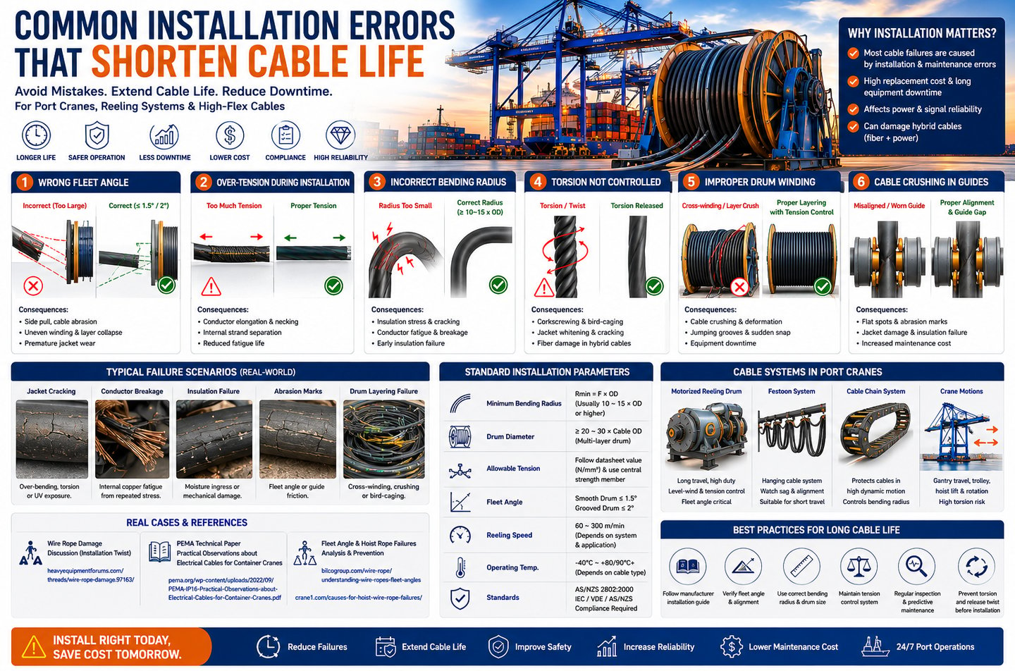
1. Wrong Fleet Angle and Alignment
If there's one error that quietly destroys more reeling cable than any other, it's a bad fleet angle.
1.1 What Fleet Angle Misalignment Is
Fleet angle is the angle between the cable as it runs from a fixed sheave and a line perpendicular to the drum axis — in plain terms, how far "off square" the cable is as it lands on the drum. The wire-rope industry has settled on well-established limits that apply equally to reeling cable: the maximum fleet angle should not exceed about 1.5° for a smooth drum and 2° for a grooved drum. Go beyond that and you're asking for trouble; go too far under it (below roughly 0.5°) and the cable piles up against the flange instead of crossing back, which is its own failure mode.
1.2 The Engineering Impact
When the fleet angle is too large, the cable doesn't seat cleanly. It gets dragged sideways onto each wrap, which produces side-loading on the cable layers, uneven winding, and abrasion as the cable rubs against flanges and against itself at crossover points. In reeling systems specifically, a poor fleet angle also injects torsion stress the cable was never meant to carry, because the cable is being twisted as it's forced into position.
1.3 How It Fails in the Long Run
None of this fails on day one — which is exactly why it's dangerous. Over weeks and months you get layer collapse as poorly seated wraps give way, concentrated abrasion at the crossover points where cables cross each other, and premature jacket wear that eventually exposes the cores. By the time the cable visibly fails, the geometry that caused it has been doing damage for a long time.
2. Over-Tension During Installation
The second great killer happens before the crane has even run a single cycle: pulling the cable in too hard.
2.1 What Goes Wrong
During installation it's tempting to haul the cable into position with whatever pulling force gets the job done. But excessive pulling force stretches the conductors beyond their elastic limit, and that deformation doesn't recover. You've damaged the cable during the one operation that was supposed to simply put it in place.
2.2 The Technical Consequences
Over-tensioned conductors "neck down" — they thin out where they've been stretched, like pulling on a piece of chewing gum. That necking creates weak points, can cause internal strand separation, and quietly destroys the cable's fatigue life. A reeling cable's whole job is to survive millions of flex cycles; a conductor that's already been stretched at install will fatigue-fracture far sooner than its rating promises. The failure shows up months later in service, which is why over-tension so often gets misdiagnosed as a cable-quality problem.
2.3 Which Cables Are Most Vulnerable
The cables most at risk are the ones doing the hardest work: 0.6/1kV crane reeling cables under sustained dynamic load, high-flex PUR-jacketed cables whose value lies entirely in their flex life, and hybrid power-plus-fibre systems — where over-tension can stretch the optical element to the point of attenuation or fracture long before the copper shows any complaint. This is also why a central strength member matters: it's there to take the tensile load so the conductors don't have to.
3. Incorrect Bending Radius
3.1 The Minimum Bending Rule
Every cable has a minimum bend radius, and it isn't a suggestion. For reeling and crane cables the requirement typically runs from 10 to 15 times the cable's outer diameter (OD), and sometimes higher depending on construction. The rule is usually written as Rmin = F × OD, where F is the manufacturer's multiplier. Bend the cable tighter than that and you cause irreversible damage — not "it might be fine," but cumulative structural harm every single cycle.
3.2 The Failure Mechanism
Bending too tight does three things at once: it cracks the insulation as it's forced past its strain limit, it drives copper fatigue fracture in the conductors on the outside of the bend, and it concentrates stress in the jacket at the tightest point. On a static cable a one-off tight bend might be survivable; on a reeling or festoon cable that hits the same tight radius thousands of times a day, it's a countdown to failure.
3.3 Where It Shows Up
The usual suspects are crane reeling systems where a guide or sheave is undersized, festoon systems where the saddle geometry forces too tight a loop, and cable chain (energy chain) systems where the chain's bend radius is smaller than the cable's minimum. The fix is almost always a system-design correction — bigger sheaves, correct chain radius — rather than a cable change.
4. Torsion Not Controlled During Installation
Torsion deserves its own section because it's the most misunderstood of the installation errors, and one of the most destructive.
4.1 The Root Cause
Torsion damage usually starts at unspooling. If the cable is pulled off the delivery drum axially (over the end) instead of tangentially (rolling the drum), every wrap that comes off injects one full twist into the cable. Pull a few hundred metres off the end of a stationary drum and you've wound hundreds of twists into a cable that was never designed to absorb them. The other common causes are failing to relieve torsion before fixing the cable in place, and misalignment during drum setup that keeps adding twist with every cycle.
4.2 The Failure Effects
Built-in torsion shows up as corkscrewing — the cable takes on a permanent helical deformation and no longer sits cleanly on the drum. In worse cases you get bird-caging, where the outer conductor layers expand away from the core like a cage, which is effectively unrecoverable. And in hybrid cables, torsion is what fractures or micro-bends the optical fibre, knocking out the data path while the power cores still appear healthy — a maddening fault to diagnose if you don't know the torsion history.
4.3 What's Most Sensitive
The cables that punish torsion errors hardest are exactly the high-value ones: PUR reeling cables built to the LAPP ÖLFLEX CRANE class, hybrid constructions such as a 4G70 power cable with integrated fibre, and AGV cabling on torsion-sensitive articulating systems. These are also the cables where good anti-torsion construction — controlled lay length, balanced layers, a proper support element — does the most good, provided the installation doesn't sabotage it first.
5. Improper Drum Winding and Layering
5.1 The Common Mistakes
Multi-layer reeling drums are unforgiving of sloppy winding. The recurring mistakes are uneven layering where wraps aren't laid side by side, the absence of any tension-control or level-wind system to guide the cable, and cross-winding or overlapping where one wrap rides up over another instead of seating next to it.
5.2 The Engineering Consequences
The physics here is brutal. When upper layers are wound over a poorly laid lower layer, the lower layer gets crushed — it's carrying the radial load of everything above it through point contacts rather than an even bed. At crossover points the cable deforms, flattening and stressing the insulation. And a wrap that's ridden up over its neighbour can suddenly drop and snap taut under load, shock-loading the cable in a way no rating accounts for.
5.3 The System-Level Risk
This is the error that takes whole cranes offline. A crushed or snapped reeling cable means an unplanned stoppage, an emergency replacement (rarely cheap, never convenient), and high maintenance cost in an operation where every hour of downtime carries a price. A level-wind system and proper tension control aren't luxuries on a multi-layer drum — they're the difference between rated life and a midnight callout.
6. Cable Crushing in Guides and Rollers
6.1 Mechanical Misalignment
The last common error is mechanical neglect in the guide and roller system. Worn rollers that no longer turn freely, incorrect spacing or geometry that pinches the cable, and a guide system that simply hasn't been maintained all conspire to crush and abrade the cable as it passes through.
6.2 The Damage Mechanism
The result is predictable: flat spots where the cable has been pressed against a seized roller, outer-sheath abrasion from dragging across worn surfaces, and internal insulation stress that you can't see until it fails electrically. A roller that's stopped turning becomes a knife that the cable saws itself against thousands of times a day. Routine inspection of rollers and guides — checking they spin, checking the spacing, replacing worn parts — is some of the cheapest insurance in the whole system.
7. Real-World Failure Cases and References
This isn't theory. The same failure modes show up again and again in field discussions and industry guidance, and it's worth reading the primary sources rather than taking our word for it.
7.1 Wire Rope and Cable Torsion Damage — Field Discussion
Practitioners on the Heavy Equipment Forums have documented how a twist introduced during installation propagates along the cable and eventually causes failure, reinforcing why controlled, tangential unspooling matters so much. The thread is a useful, unvarnished look at how torsion damage actually unfolds in the field: https://www.heavyequipmentforums.com/threads/wire-rope-damage.97163/
7.2 PEMA Technical Insights on Crane Cable Failures
The Port Equipment Manufacturers Association (PEMA) — the global industry body whose members include the major crane and cable manufacturers — published an information paper, Practical Observations about Electrical Cables for Container Cranes (IP16), analysing how torsion, tension and installation practice affect container-crane cable behaviour. It's the most authoritative single document on this topic and is well worth reading in full: https://www.pema.org/wp-content/uploads/2022/09/PEMA-IP16-Practical-Observations-about-Electrical-Cables-for-Container-Cranes.pdf
7.3 Fleet Angle and Hoist Rope Failure Analysis
For the fleet-angle side, two practical references lay out both the geometry and the preventive engineering. Bilco's explainer walks through how fleet angle is defined and why misalignment is a primary failure factor, and Crane1's analysis covers the broader causes of hoist-rope failure and how to prevent them: https://www.bilcogroup.com/wire-rope/understanding-wire-ropes-fleet-angles https://crane1.com/causes-for-hoist-wire-rope-failures/
7.4 Additional Field Discussion
For more practitioner-level discussion of drum winding and spooling problems, the Heavy Equipment Forums archive is searchable for terms like "crane cable drum" and "wire rope spooling": https://www.heavyequipmentforums.com
8. The Engineering Parameters That Prevent Failure
If sections 1 through 6 are the diseases, here are the numbers that act as the cure. These are the parameters worth writing into your installation spec and checking on site.
Minimum bending radius. Use Rmin = F × OD. Reeling cables typically need 10–15 × OD or more; confirm the multiplier on the specific cable's datasheet and design every sheave, guide and chain around it. The cable's minimum radius sets the system geometry, not the other way around.
Allowable tension. Tension limits are defined per unit of conductor cross-section (in N/mm²) and must be respected during both installation and operation. A central strength member is strongly recommended on reeling cables so the support element carries the tensile load and the conductors are left to do only their electrical job.
Drum diameter ratio. The drum (and any sheave the cable wraps) should generally be at least 20–30 × the cable diameter. This is especially critical for multi-layer winding, where too small a drum forces a tight radius on every layer and compounds the crushing problem.
Reeling speed. Typical systems run somewhere in the 60–300 m/min range depending on design, but higher speed isn't free: it increases both torsion and abrasion risk per cycle and narrows the margin for any other error. Where speed is high, fleet angle and winding quality have to be correspondingly tighter.
Get these four right and you've eliminated the conditions behind the vast majority of premature failures.
9. Matching the Cable System to the Application
Different crane systems stress cable in different ways, and the right installation practice follows from the system type.
Motorised drum reeling systems, used on STS and RTG cranes, are the most demanding. They need a level-wind system, active tension control, and optimised fleet angle working together — the multi-layer drum is where every error in this article compounds.
Festoon systems carry hanging cable over short travel and are most sensitive to sagging and misalignment; the cable's own weight and loop geometry are the things to watch.
Cable chain (energy chain) systems, common in robotics and automation, constrain movement to the chain's geometry — so the governing rule is simply that the chain's bend radius must respect the cable's minimum.
Overall crane motion layers these together: gantry travel, trolley movement, and spreader rotation each move cable differently, and spreader rotation in particular is a high-torsion situation that demands genuine anti-torsion cable and torsion-aware installation.
Specifying the right cable construction for each of these — and installing it to the parameters above — is the whole game.
10. Conclusion: Good Cable, Installed Right
The single most important takeaway is the one we opened with: most crane cable failures are caused by installation and system-design errors, not material defects. Fleet angle, tension, bend radius, torsion control, drum winding, and guide maintenance — these six things decide whether a cable reaches its rated life or fails early. A premium cable installed badly will fail; a well-engineered cable installed correctly will go the distance.
That's also the honest answer to the buyer's question of whether a cost-effective alternative can really compete with the premium brands. When installation is the dominant variable, what you need from a cable supplier is sound engineering — correct anti-torsion construction, the right strength member, accurate datasheets with real bend-radius and tension figures — and a partner who'll help you specify and install it properly. That's exactly what we do.
We're Feichun. We manufacture heavy-duty, customisable crane, mining and port cable — high-flex reeling and trailing cable, PUR and rubber sheathed, with proper anti-torsion construction and central strength members, plus hybrid power-plus-fibre designs for automated equipment. Just as importantly, we'll work with your engineers on the installation parameters — bend radius, fleet angle, drum ratio, tension and reeling speed — so the cable you buy actually delivers the life it's rated for.
If you're specifying cable for a port or crane project, or trying to get to the bottom of repeat failures on an existing system, send us your requirement — cable type, voltage class, conductor configuration, the crane and reeling system it runs on, and the standards your engineer needs met. We'll come back with a clear quote and the construction and installation detail behind it. Get in touch, and let's make sure the next cable lasts.
This article is a general industry overview, not engineering advice for any specific installation. Always follow the cable manufacturer's published installation instructions and the relevant electrical and safety standards for your equipment and jurisdiction. External references are provided for further reading and are the property of their respective publishers; brand and product names are referenced for technical comparison only.
How to Reach Us
Get in Touch
SiteMap
Product Catalogue
Festoon Cable
Shore Power Cable




Scan to add us on WeChat