
CORDAFLEX(SMK)-V (N)SHTOEU: Comprehensive Guide to Low Voltage Vertical Reeling Cables
High-performance flexible low voltage reeling cable designed for vertical reeling operations under extreme mechanical stresses. CORDAFLEX SMK-V specifications, features & applications.
hongjing.Wang@Feichun
11/27/202513 min read
Introduction to Vertical Reeling Cable Technology
Vertical reeling cables represent a specialized category of flexible power cables engineered specifically for applications where extreme mechanical stresses occur during vertical lifting operations. Unlike standard horizontal reeling cables that primarily handle lateral movement, vertical reeling cables must withstand substantially different force vectors, including continuous gravitational loads, dynamic acceleration forces, and complex bending patterns that occur when cables transition from vertical to horizontal planes.
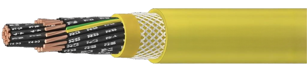
The CORDAFLEX(SMK)-V (N)SHTOEU cable exemplifies advanced vertical reeling cable design, incorporating specialized construction features that address the unique challenges of spreader reeling applications and vertical hoist operations. This cable type finds primary application in container handling equipment, gantry cranes, and specialized lifting systems where reliable power transmission during vertical movement is critical.
The fundamental distinction between vertical and horizontal reeling applications lies in the mechanical stress profile. Vertical applications subject cables to constant tensile loads equal to the cable's suspended weight plus dynamic forces from acceleration and deceleration. This continuous tension, combined with frequent bending cycles and potential torsional stress, creates an operating environment that demands exceptional mechanical performance characteristics beyond those required for horizontal applications.
Core Application Areas for Vertical Reeling Cables
Spreader Reeling Systems
Spreader reeling applications represent one of the most demanding cable applications in material handling operations. Container spreaders require reliable electrical connections while moving vertically at speeds up to 240 meters per minute, lifting and lowering cargo containers weighing tens of tons. The cable must maintain electrical integrity while experiencing rapid vertical movement, frequent directional changes, and varying load conditions.
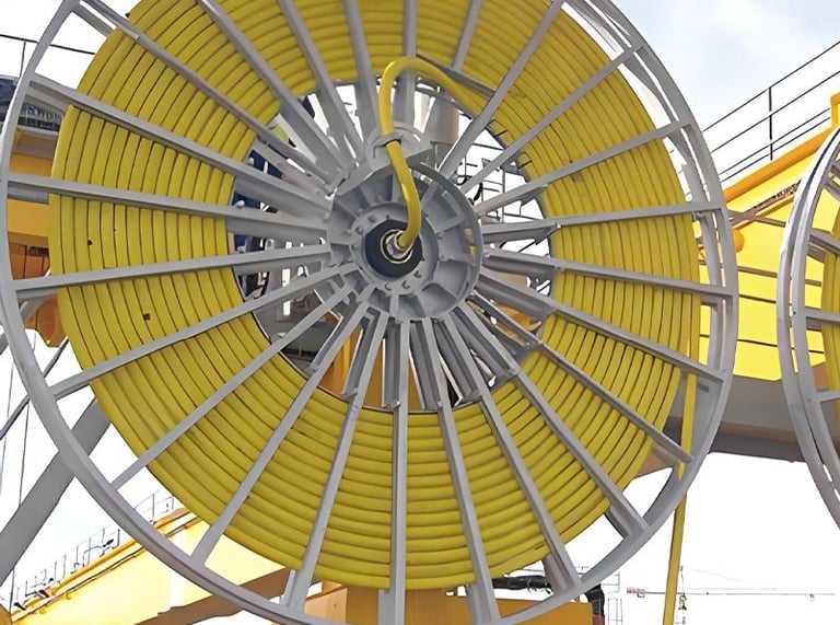
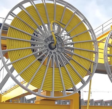
In spreader applications, the cable typically pays out from a reel mounted on the crane trolley as the spreader descends, then rewinds as the spreader rises. This continuous winding and unwinding action, combined with the vertical orientation and substantial self-weight of long cable lengths, creates unique mechanical challenges. The cable must resist elongation under its own weight while maintaining flexibility sufficient for proper spooling onto the drum.
Vertical Hoist Operations
Vertical hoist systems utilize reeling cables to power lifting mechanisms that move exclusively or primarily in the vertical plane. These applications include construction tower cranes, ship-to-shore container cranes, and specialized industrial lifting equipment. The vertical travel distances can range from tens to hundreds of meters, with corresponding cable lengths that generate significant self-weight loads.
The operational profile of vertical hoist cables includes frequent start-stop cycles, variable speed operation, and potential emergency stop situations that introduce shock loads. The cable design must accommodate these dynamic forces while maintaining consistent electrical performance and mechanical integrity throughout the expected service life.
Port Terminal Equipment
Modern port terminal operations rely heavily on automated container handling systems that incorporate vertical reeling cables as essential power transmission components. Rubber-tired gantry cranes (RTGs), rail-mounted gantry cranes (RMGs), and automated stacking cranes all utilize vertical reeling cables to power spreaders and lifting mechanisms. These applications demand exceptional reliability, as equipment downtime directly impacts terminal throughput and operational efficiency.
Port environments introduce additional challenges including exposure to corrosive salt air, temperature extremes, UV radiation, and potential contamination from cargo residues. Vertical reeling cables for port applications must deliver mechanical performance while withstanding these environmental factors throughout extended service intervals.
Technical Specifications and Construction Features
Conductor Design
The CORDAFLEX(SMK)-V cable utilizes electrolytic bare copper conductors manufactured to very fine stranding class FS specifications. This conductor classification provides significantly greater flexibility compared to standard class 5 stranding, reducing internal stress during bending cycles and improving fatigue resistance. The very fine stranding incorporates numerous individual wire elements of small diameter, allowing the conductor to bend repeatedly without work-hardening or strand breakage that would eventually lead to conductor failure.
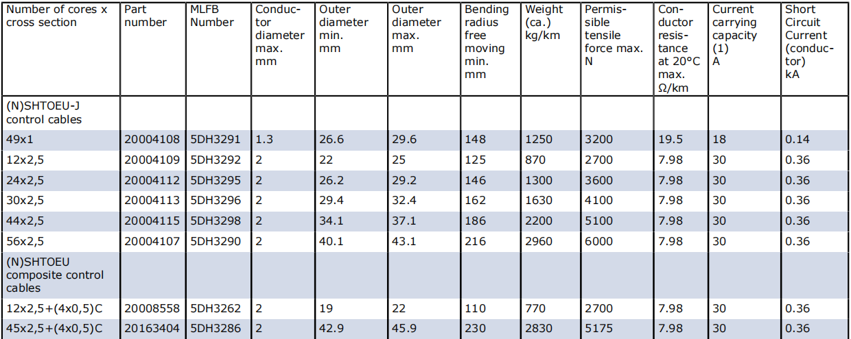
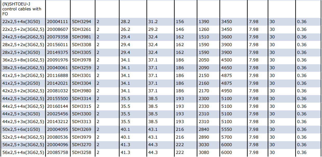
The conductor cross-sections available in vertical reeling cables range from smaller control cable sizes (1.5 mm²) to substantial power conductors (56 mm² and larger for some configurations). This range accommodates both power transmission and control signal requirements within integrated cable designs. The conductor resistance values specified at 20°C provide baseline electrical performance data, with temperature correction factors applied for operation at elevated conductor temperatures up to 90°C.
Specialized Insulation System
The insulation system employs a special thermoplastic compound engineered for high thermal stability and excellent insulation resistance retention. Unlike standard insulation materials, this compound maintains stable electrical properties across wide temperature ranges and provides superior gliding characteristics that reduce friction between cable components during flexing. This reduced internal friction translates to lower heat generation and extended mechanical life.
The insulation design incorporates black-colored material with white printed numbering for positive conductor identification. This high-contrast marking system ensures reliable conductor identification even after extended service in challenging environments. The earth conductor utilizes distinctive green-yellow coloring per international safety standards, providing immediate visual recognition of the protective conductor.
Individual Screening Options
For applications requiring electromagnetic compatibility or reduced electrical interference, individual conductor screening is available using tinned copper wire braids. The screening design achieves optimized transfer impedance at 30 MHz, effectively attenuating high-frequency interference while maintaining cable flexibility. Surface coverage specifications ensure adequate shielding effectiveness: minimum 60% for shielded individual cores, and minimum 80% for twisted shielded pairs used in control and communication circuits.
The screening system serves dual purposes: electromagnetic interference (EMI) protection for sensitive control signals and capacitive coupling reduction between adjacent conductors. In applications with variable frequency drives or other sources of electrical noise, proper screening becomes essential for reliable control system operation.
Multi-Layer Sheath System Architecture
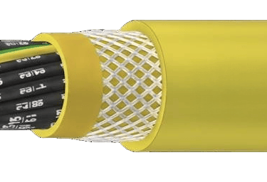
The sheath system represents a critical design element that distinguishes vertical reeling cables from standard flexible cables. The CORDAFLEX(SMK)-V construction employs a sophisticated three-layer sheath architecture specifically engineered for extreme mechanical stress resistance.
The inner sheath utilizes PROTOFIRM Special compound, a high-grade formulation based on polychloroprene (PCP) material in yellow color. This inner layer provides mechanical support, environmental sealing, and serves as the foundation for the anti-torsion reinforcement. Between the inner and outer sheaths, a reinforced polyester braid provides torsional stability and additional tensile strength. This anti-torsion braid creates a vulcanized bond with both sheath layers, effectively integrating the reinforcement into the overall cable structure rather than allowing independent movement that would reduce effectiveness.
The outer sheath employs abrasion and tear-resistant special rubber compound also based on PCP, finished in yellow for high visibility. This outer layer withstands mechanical abuse from contact with structural elements, resists environmental degradation from UV exposure and ozone, and provides oil resistance per DIN EN 60811-404 specifications. The combination of these three integrated layers creates a robust protection system that significantly extends cable service life in demanding vertical applications.
Aramid Support Elements
A defining characteristic of vertical reeling cables is the incorporation of central aramid support elements to increase load-carrying capability beyond what the copper conductors alone can sustain. Aramid fibers provide exceptional tensile strength-to-weight ratios, offering substantial load-bearing capacity without adding excessive cable weight or reducing flexibility.
The aramid support element designation includes the breaking load value expressed in kilonewtons (kN), indicating the maximum tensile force the support element can withstand before failure. This specification allows precise cable selection based on the actual suspended weight and dynamic forces present in the application. The support element carries the primary mechanical loads, effectively relieving the copper conductors of excessive tension that would otherwise cause elongation, permanent deformation, or eventual breakage.

Electrical Performance Parameters
Voltage Ratings and Applications
The rated voltage of 0.6/1 kV (expressed as U₀/U where U₀ represents voltage between conductor and earth, and U represents voltage between conductors) suits the cable for a wide range of industrial power distribution applications. The maximum permissible AC operating voltage extends to 0.7/1.2 kV, providing a safety margin for voltage fluctuations and transient conditions. For DC applications, the maximum permissible operating voltage reaches 0.9/1.8 kV, reflecting the different stress patterns that DC voltage imposes on insulation systems.
The AC test voltage specification of 3.5 kV applied for 5 minutes verifies insulation integrity and provides assurance of dielectric strength. This test voltage, substantially higher than operating voltage, ensures adequate safety margins and identifies potential insulation defects before the cable enters service.
Current Carrying Capacity
Current carrying capacity determination follows DIN VDE 0298-4 guidelines, accounting for installation conditions, ambient temperature, and conductor configuration. The actual current rating depends on multiple factors including conductor cross-section, number of simultaneously loaded cores, installation method (suspended in air versus contact with surfaces), and ambient temperature.
For vertical reeling applications, heat dissipation characteristics differ from horizontal installations due to the vertical orientation and air circulation patterns. Suspended cables benefit from air circulation around the entire cable circumference, potentially allowing higher current ratings compared to cables in contact with reel drums or cable trays. However, the self-heating effect in long vertical runs requires consideration, as heat generated in lower sections must dissipate while conducting through upper cable sections.
Data Transmission Integration
Modern vertical reeling applications frequently require integration of data transmission capabilities alongside power conductors. The CORDAFLEX(SMK)-V design accommodates special elements for ASI-Bus, Profibus, CAN-Bus, and Industrial Ethernet protocols. These fieldbus systems enable communication between control systems and field devices, supporting automated material handling operations.
Alternatively, fiber optic elements can be integrated for transmitting all bus protocols with complete immunity to electromagnetic interference. Fiber optics eliminate concerns about electrical noise coupling, ground loops, and voltage differences between equipment, providing reliable high-speed data transmission in electrically noisy industrial environments. The fiber optic option becomes particularly valuable in applications with variable frequency drives or other sources of significant electrical interference.
Mechanical Performance Characteristics
Enhanced Tensile Load Capability
The incorporation of additional aramid support elements provides increased tensile load capability substantially exceeding that of standard reeling cables. While conventional flexible cables typically limit tensile stress to 15 N/mm² of conductor cross-section, the vertical reeling design with aramid reinforcement safely handles the continuous tensile loads inherent in vertical applications.
The actual permissible tensile force depends on the specific cable configuration, aramid support element specifications, and application requirements. The cable manufacturer provides detailed load ratings for each cable configuration, accounting for both static weight and dynamic forces from acceleration and deceleration. Users must calculate total suspended cable weight based on vertical travel distance, then add dynamic forces based on maximum acceleration rates to determine required support element capacity.
Torsional Stress Tolerance
Torsional stress resistance becomes critical in vertical reeling applications where cable path changes and reel geometry can introduce twisting forces. The maximum torsional stress rating of ±50 degrees per meter (°/m) indicates the cable's ability to withstand significant twisting without damage. This torsional capability accommodates minor misalignments in cable guidance systems and oblique payout conditions that might occur during operation.
The anti-torsion braid incorporated in the sheath system provides mechanical resistance to twisting forces, distributing torsional stress throughout the cable structure rather than concentrating it in individual components. This design prevents progressive unwinding of conductor strands or core groups that would otherwise occur under repeated torsional loading.
Bending Radius Requirements
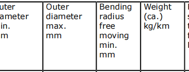
Minimum bending radius specifications according to DIN VDE 0298 part 3 establish safe limits for cable routing and installation. The bending radius represents the smallest curve radius the cable should experience during installation or operation without risking mechanical damage or reduced service life. For S-type directional changes where the cable reverses direction, the minimum distance specification of 20 times the cable diameter (20 × D) ensures adequate transition geometry.
In vertical reeling applications, bending occurs primarily at the transition from reel to vertical drop, at intermediate sheaves or guides if present, and potentially at the spreader or load connection point. Each bending location must satisfy minimum radius requirements while accounting for the tensile loads present at that point. Higher tensions require larger bending radii to maintain acceptable stress levels in cable components.
Operational Speed Capabilities
The travel speed capability up to 240 meters per minute for vertical operations represents substantial performance for material handling applications. This speed rating assumes proper installation with appropriate reel diameter, proper cable support, and compliance with all mechanical parameter specifications. For applications requiring speeds exceeding 240 m/min, consultation with the cable manufacturer becomes essential to verify suitability and potentially specify enhanced designs.
The speed rating reflects multiple considerations including heat generation from flexing, wear rates at contact points, dynamic forces during acceleration and deceleration, and the cable's ability to properly spool onto the reel at high speeds. In applications with frequent start-stop cycles, the average speed may be less critical than peak acceleration rates, which can introduce substantial shock loads exceeding steady-state forces.
Thermal Properties and Environmental Performance
Operating Temperature Range
The maximum permissible conductor temperature of 90°C establishes the thermal limit for continuous operation, while the maximum short-circuit temperature of 250°C defines the brief overload capability. The substantial difference between these values reflects the insulation system's ability to withstand momentary thermal excursions during fault conditions without permanent degradation.
For fixed installation, the cable operates reliably across ambient temperatures from -50°C to +80°C. During fully flexible operation, the range narrows slightly to -35°C to +80°C, reflecting the increased mechanical demands of flexing combined with cold-temperature stiffening of elastomeric materials. These temperature ranges accommodate operation in diverse climates from arctic cold storage facilities to tropical port terminals.
Chemical and Environmental Resistance
Oil resistance compliance with DIN EN 60811-404 and DIN VDE 0473-811-404, paragraph 10, ensures the cable withstands exposure to hydraulic fluids, lubricants, and petroleum-based substances commonly present in industrial environments. This resistance prevents sheath swelling, softening, or degradation that would compromise mechanical protection and reduce service life.
Weather resistance encompasses multiple environmental factors: ozone resistance prevents cracking from atmospheric ozone exposure, UV resistance maintains sheath integrity despite sunlight exposure, and moisture resistance ensures water ingress does not degrade electrical properties. The verified long-term water resistance makes the cable suitable for outdoor installations and applications where water contact may occur.
Common Application Challenges and Solutions
Challenge: Cable Elongation Under Load
Problem: In vertical applications with substantial cable weight, permanent elongation of the cable can occur over time, leading to loose winding on the reel, improper cable management, and potential mechanical damage.
Solution: The aramid support element specifically addresses this challenge by carrying tensile loads rather than stressing the copper conductors and other cable components. The aramid fibers exhibit minimal creep under sustained loading, maintaining cable length stability throughout the service life. Proper support element selection based on actual suspended weight plus a safety factor prevents elongation issues. Additionally, regular inspection of cable winding patterns on the reel allows early detection of any elongation, enabling corrective action before damage occurs.
Challenge: Accelerated Wear at Transition Points
Problem: Points where the cable transitions from vertical to horizontal orientation or passes over sheaves experience concentrated mechanical stress, leading to accelerated wear, flattening, or damage to the outer sheath.
Solution: Several factors address this challenge. First, adherence to minimum bending radius specifications ensures stress levels remain within acceptable limits. Second, the robust three-layer sheath system with reinforced anti-torsion braid provides enhanced resistance to abrasion and mechanical deformation. Third, proper sheave or roller selection with adequate diameter and smooth surfaces minimizes contact pressure and friction. Finally, ensuring appropriate cable guidance alignment prevents oblique angles that would increase side loading at transition points.
Challenge: Torsional Stress From Reel Misalignment
Problem: Misalignment between the cable reel and vertical cable path introduces torsional stress that can cause core twisting, conductor damage, and premature failure.
Solution: The ±50 °/m torsional stress rating provides tolerance for minor misalignments, while proper installation practices minimize torsional loading. Cable guidance systems should align the reel axis perpendicular to the vertical cable path. For applications where some misalignment is unavoidable, careful cable routing can distribute torsional stress over greater lengths, reducing stress concentration. The anti-torsion braid in the sheath system provides mechanical resistance to twisting, further protecting against torsional damage.
Challenge: Electromagnetic Interference in Control Circuits
Problem: Variable frequency drives, welding equipment, and other electrical noise sources can induce interference in control signal circuits, causing erratic operation or communication errors.
Solution: Individual screening of control conductors or twisted shielded pairs effectively attenuates electromagnetic interference. The screening achieves optimized transfer impedance at 30 MHz, providing excellent high-frequency noise rejection. Proper screen termination at both ends with continuous screen connection throughout the cable run maximizes screening effectiveness. For applications with severe electrical noise, fiber optic data transmission eliminates susceptibility to electromagnetic interference entirely, ensuring reliable communication regardless of electrical environment.
Challenge: Thermal Management in High-Duty-Cycle Applications
Problem: Frequent high-speed lifting cycles generate heat from both conductor current and mechanical flexing, potentially exceeding temperature limits and accelerating insulation aging.
Solution: Proper current rating selection ensures conductor heating remains within specified limits. The suspended installation method typical of vertical applications provides excellent heat dissipation through natural convection, allowing higher current ratings compared to enclosed installations. In extreme duty cycles, operational monitoring of cable temperature using infrared thermography identifies potential thermal issues before damage occurs. Additionally, cable design modifications including larger conductor cross-sections or enhanced cooling provisions can be specified for exceptionally demanding applications.
Challenge: Difficult Installation in Existing Systems
Problem: Replacing cables in operational crane systems often requires threading cables through confined spaces, around obstructions, and through cable guidance systems, with limited access for pulling equipment.
Solution: The flexible design and relatively compact cross-section of vertical reeling cables facilitate installation compared to rigid or semi-rigid cable types. Installation planning should include cable route assessment, identification of pulling points, and arrangement of appropriate pulling equipment. For long vertical runs, intermediate support during installation prevents excessive cable weight from creating unsafe conditions or damage. Cable manufacturers can provide pulling grip devices specifically designed for the cable construction, distributing pulling forces appropriately and preventing damage during installation.
Installation Best Practices and Maintenance Considerations
Proper Reel Sizing and Configuration
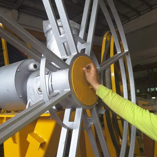
Reel diameter selection significantly impacts cable performance and service life. The reel diameter must satisfy minimum bending radius requirements while accounting for the tensile load present when the cable is fully extended. Larger reel diameters reduce bending stress but increase the overall system size and weight. The reel design should provide proper cable guidance through flanges or helical grooves that maintain organized winding and prevent cable crossovers or tangles.
The center feeding point arrangement requires careful attention to cable routing, ensuring the transition from the infeed to the reel maintains appropriate bending radii and avoids sharp direction changes. Proper cable support at the infeed point prevents excessive stress concentration and provides smooth cable motion during reeling and unreeling cycles.
Installation Inspection Points
Comprehensive inspection during installation identifies potential issues before the system enters service. Key inspection points include verification of bending radii at all transition points, confirmation of proper reel alignment, assessment of cable routing for potential interference or abrasion points, and verification of electrical continuity and insulation resistance. Documentation of installation parameters provides baseline data for future maintenance and troubleshooting.
Operational Monitoring and Maintenance
Regular inspection during operation extends cable service life by identifying developing issues before failure occurs. Visual inspection should assess outer sheath condition for signs of abrasion, cuts, or deterioration. Mechanical assessment includes checking cable winding pattern on the reel for evenness and proper alignment, and observing cable motion during operation for unusual behavior such as twisting or binding.
Electrical testing at scheduled intervals verifies continued insulation integrity and conductor continuity. Infrared thermography during operation identifies hot spots that might indicate electrical or mechanical problems. Maintenance records documenting inspection findings, test results, and any corrective actions taken provide valuable trend data and support predictive maintenance planning.
Conclusion
The CORDAFLEX(SMK)-V (N)SHTOEU vertical reeling cable represents specialized engineering addressing the unique challenges of spreader reeling and vertical hoist applications. The combination of aramid support elements, robust three-layer sheath construction, very fine stranded conductors, and comprehensive electrical and mechanical design creates a cable solution capable of reliable performance in demanding vertical applications.
Success in vertical reeling applications requires appropriate cable selection, proper installation following manufacturer guidelines, and ongoing maintenance attention. Understanding the mechanical and electrical demands of the specific application allows informed cable specification and installation practices that maximize performance and service life. The enhanced capabilities of purpose-designed vertical reeling cables provide essential reliability for modern material handling operations where equipment downtime directly impacts productivity and operational costs.
How to Reach Us
Get in Touch
SiteMap
Product Catalogue
Festoon Cable
Shore Power Cable




Scan to add us on WeChat