Critical Ampacity Design Mistakes in Port Power Cable Projects: specialty Analysis
Avoid costly cable failures in port environments. Learn from analysis of ampacity design mistakes including derating factors, soil thermal properties, and load growth planning for reliable power systems.
hongjing.Wang@Feichun
7/11/20255 min read
Introduction: The Critical Stakes of Port Cable Design
In my company’s 15+ years of marine electrical engineering experience, we’ve encountered recurring issues in port cable installations—many of which trace back to fundamental oversights in current-carrying capacity (ampacity) design. When cables fail in ports, the consequences are far-reaching: interrupted operations, massive financial losses, and in the worst cases, safety incidents.
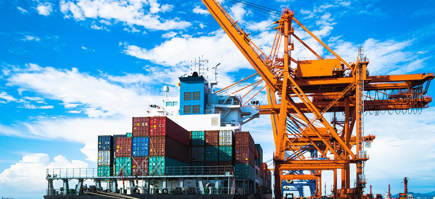
Ports are high-load, high-risk environments. Unlike typical commercial or industrial settings, they present unique challenges that amplify the importance of precise ampacity calculations. From buried cable runs exposed to salt-laden air to high ambient temperatures from sunlight beating down on exposed structures, standard approaches simply don’t cut it.
Understanding Current-Carrying Capacity in Port Environments
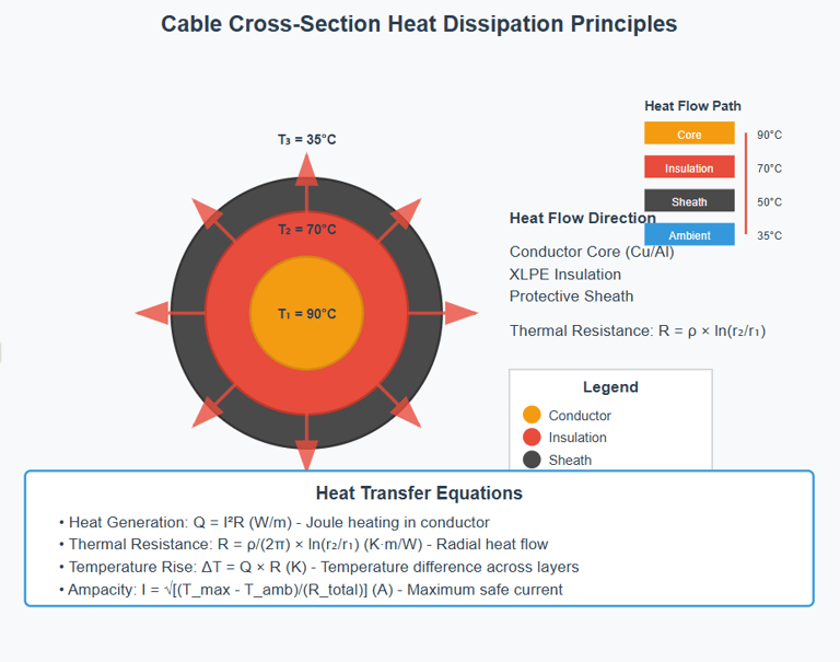
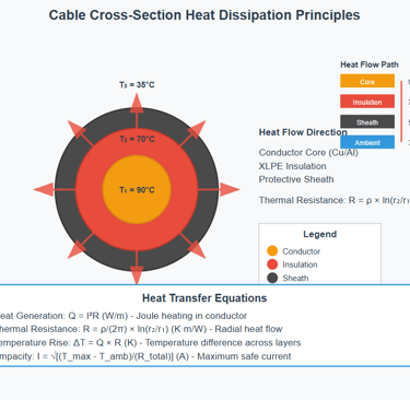
At its core, ampacity refers to the maximum current a cable can carry continuously without exceeding its temperature rating. It’s fundamentally linked to thermal management: more current equals more heat, which must be dissipated effectively to avoid insulation breakdown.
Ports complicate this picture. Factors like proximity to seawater, enclosure in concrete ducts, or grouping in confined trays all influence thermal conditions. Complying with international standards like IEC 60287, IEEE 835, or regional maritime regulations is essential—but real-world variables often go beyond the assumptions those models were built on.
A deeper understanding of heat generation in conductors, insulation materials, and the thermal resistivity of the surrounding environment is essential for robust electrical cable design.
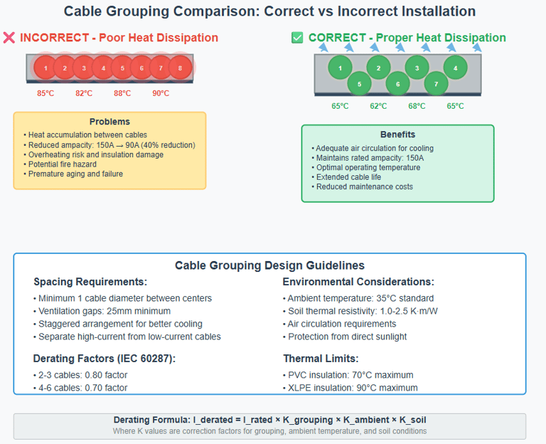
Mistake #1: Ignoring Cable Grouping and Bundling Effects
One of the most common current-carrying capacity design mistakes in port projects is neglecting the impact of cable grouping. In a recent case, a container crane’s main power feed failed prematurely. Investigation revealed that cables rated for 150 amps had been bundled together in a tray—resulting in mutual heating and a real-world ampacity of less than 100 amps.
Cable grouping derating factors in port installations are not optional—they’re critical. When multiple cables share the same conduit or duct, their combined heat load reduces each one’s ability to dissipate heat. Standards like IEC 60287-2-1 provide adjustment factors, but these must be applied thoughtfully.
Design strategies include:
Increasing spacing between cables
Using thermally conductive fillers
Applying forced ventilation or active cooling
Employing thermal modeling for port power cable systems in congested areas
Mistake #2: Overestimating Soil Thermal Properties
Buried cables offer protection from mechanical damage but introduce a new risk: reliance on soil thermal properties for heat dissipation. In one field experience, a high-voltage port cable failed due to excessive heating. The design assumed a soil thermal resistivity of 1.2 K·m/W, but field tests later revealed it was closer to 2.5 K·m/W.
Soil thermal resistivity effects on buried port cables are substantial. Loose, dry, or sandy soils dramatically reduce heat transfer, increasing cable operating temperatures.
Best practices include:
Site-specific thermal resistivity testing
Conservative default values (≥2.0 K·m/W)
Using thermally stabilised backfill materials like bentonite or sand-cement mixes
Mechanical compaction to improve soil contact
Mistake #3: Neglecting Ambient Temperature and Heat Accumulation
Ambient temperature directly affects cable ampacity. In ports, factors like radiant heat from sunlit surfaces or the thermal mass of enclosed ducts can push temperatures far beyond standard assumptions.
Designing without factoring in ambient temperature considerations for port cable design leads to chronic overheating. Engineers should expect continuous operation in hot environments and account for heat accumulation due to poor ventilation.
Recommendations:
Limit continuous loads to 80–90% of rated ampacity in hot zones
Consider seasonal extremes (e.g., Australian summer surface temperatures)
Use shading, thermal insulation, or ventilation ducts
Install temperature sensors to monitor cable heating
Mistake #4: Failing to Plan for Load Growth and System Evolution
Ports are expanding rapidly—with automation, electrification of cranes, and shore power systems increasing electrical demands. In one recent project, a port installed shore power systems without upgrading the feeder cables. The result: overloads and insulation degradation within a year.
Load growth planning for port electrical infrastructure is a must. Oversizing is one approach, but a more sustainable solution involves strategic infrastructure upgrades and phased planning.
XLPE cable selection for harsh port environments also plays a role. XLPE cables can withstand operating temperatures up to 90°C (and 105°C under emergency conditions), making them ideal for future-proof designs.
Design tips:
Forecast electrical demand 10–20 years ahead
Use modular cabling and raceways for easy expansion
Implement load monitoring and predictive maintenance systems
Advanced Ampacity Design Strategies
Modern port projects are adopting sophisticated techniques to enhance cable reliability.
Thermal modeling for port power cable systems uses software tools to simulate real-world installation conditions. These models factor in cable size, installation method, surrounding materials, and environmental conditions.
Dynamic rating systems adjust ampacity based on real-time temperatures, allowing for safe operation under fluctuating loads.
Other innovations:
Fault current protection with thermal sensors
Integration with port energy management systems
SCADA-based monitoring for early warnings
Standards, Codes, and Compliance Requirements
Every port project must align with international and local standards. For ampacity design, key references include:
IEC 60287 – electric cable current rating calculations
IEEE 835 – cable ampacity in North America
NEMA standards – for industrial cable types
Marine-specific codes from Lloyd’s Register, DNV, and ABS
Certification agencies often require detailed documentation and testing, especially in international shipping terminals. Insurance underwriters may reject claims for damages if cable derating was ignored during design.
Cost-Benefit Analysis of Proper Ampacity Design
While thorough ampacity design might increase upfront costs, it pays off through lower maintenance, fewer outages, and extended asset life.
ROI analysis shows that avoiding a single major cable failure can offset the cost of advanced modeling or higher-grade cables.
Key savings areas:
Longer cable life and deferred replacement
Lower insurance premiums
Reduced unplanned downtime
Lower heat-related energy losses
Expert Recommendations and Design Checklist
Here’s a quick step-by-step guide to getting ampacity design right:
Calculation Steps:
Determine expected load (average and peak)
Identify installation method and environment
Apply derating factors (grouping, soil, temperature)
Select cable type and insulation class
Validate with thermal modeling
Checklist for Environmental Factors:
Soil type and resistivity test
Ambient temperature profiling
Cable routing and spacing plan
Future load expansion allowance
Avoidance Strategy Summary:
Never assume default values
Avoid tight cable groupings
Monitor post-installation cable temperatures
Engage specialist electrical engineers for modeling
Future Trends in Port Cable Design
The port power cable industry is evolving rapidly. Trends include:
Smart cable monitoring technologies with embedded sensors
Advanced materials like EPR and flame-retardant XLPE for harsh environments
Integration with renewable energy systems like offshore wind and solar
Digitalization and load prediction using AI in port energy management
These innovations promise greater reliability, energy efficiency, and safety.
Conclusion: Building Reliable Port Power Infrastructure
For engineers and port project managers, the message is clear: conservative and detailed electrical cable design is essential to building resilient port infrastructure. Each design mistake—from underestimating soil resistivity to ignoring future load growth—can result in failures that disrupt critical maritime operations.
By prioritising accuracy, thorough environmental assessments, and embracing modern design tools, ports can ensure safe, efficient, and future-ready power delivery systems.
Long-term reliability isn’t just about cables—it’s about protecting productivity, people, and profits.
How to Reach Us
Get in Touch
SiteMap
Product Catalogue
Festoon Cable
Shore Power Cable


Scan to add us on WeChat