

Drain Wire & Continuity Wire: Complete Guide to Shielded Cable Grounding
Discover drain wire and continuity wire in shielded cables: functions, materials, and benefits for EMC and signal integrity in data & instrumentation applications.
hongjing.Wang@Feichun
12/23/20257 min read
In modern electrical and electronic systems, maintaining signal integrity while managing electromagnetic interference has become increasingly critical. As data transmission speeds accelerate and electronic devices proliferate in industrial environments, the need for effective cable shielding solutions has never been more important. At the heart of many shielded cable designs lies a simple yet ingenious component: the drain wire, also known as a continuity wire or contact conductor.


What is a Drain Wire in Shielded Cables?
A drain wire is an uninsulated conductor strategically positioned in direct contact with a cable's electromagnetic shield or screen. Unlike the insulated conductors that carry signals or power, this specialized wire serves a singular, vital purpose: providing a low-resistance path to ground for unwanted electrical noise and interference captured by the shielding system.
The drain wire's placement is deliberate—it runs parallel to the cable's length, maintaining continuous physical contact with the inner surface of the shield. This direct contact ensures that any electromagnetic interference (EMI) or radio frequency interference (RFI) intercepted by the shield can be immediately conducted away to a ground reference point, preventing it from affecting the signal-carrying conductors within.
Understanding Cable Shielding and EMC Fundamentals
Before diving deeper into drain wire functionality, it's essential to understand the broader context of cable shielding. Electromagnetic compatibility (EMC) refers to a device's ability to operate properly in its electromagnetic environment without introducing intolerable disturbances to other equipment. Shielded cables play a crucial role in achieving EMC compliance by creating a conductive barrier that blocks external electromagnetic fields from penetrating to the signal conductors inside.
However, a shield alone isn't enough. When electromagnetic waves strike the shield, they induce electrical currents on its surface. Without a proper path to ground, these induced currents can circulate within the shield, potentially creating their own interference or even compromising the shielding effectiveness. This is where the drain wire becomes indispensable.
How Does a Drain Wire Improve Signal Integrity?
Signal integrity encompasses the quality and reliability of electrical signals as they travel through transmission media. In high-speed data applications, even minor electromagnetic disturbances can cause signal degradation, increased crosstalk between adjacent conductors, timing jitter, or complete data corruption.
The drain wire continuity cable grounding mechanism addresses these challenges through several key functions:
Noise Dissipation: When the shield intercepts electromagnetic interference, the drain wire provides an immediate, low-impedance route for these unwanted currents to flow to ground, effectively removing them from the cable system before they can couple into the signal conductors.
Simplified Termination: During installation, technicians can easily connect the drain wire to the connector's ground terminal or equipment chassis. This is far simpler than trying to terminate the shield itself, which may be a thin foil or fine braided mesh that's difficult to work with reliably.
Continuous Grounding: The drain wire ensures electrical continuity along the entire cable length. Even if the shield experiences minor damage or discontinuities, the drain wire maintains the grounding path.
Material Options: Class 1, Class 2, and Class 5 Copper Stranded Conductors
The performance and reliability of a drain wire heavily depend on its conductor construction. Industry standards define several classes of copper conductors, each with distinct characteristics:
Class 1: Solid Copper Conductor
Class 1 conductors consist of a single solid copper wire. This construction offers several advantages: it's the most cost-effective option, provides excellent electrical conductivity, and is simple to manufacture. For stationary installations where the cable experiences minimal flexing or movement, solid copper drain wires perform admirably.
However, solid conductors have a critical limitation: they're inflexible and susceptible to work hardening and fatigue failure when subjected to repeated bending. If a Class 1 drain wire breaks, electrical continuity is completely lost, potentially compromising the entire shielding system.
Class 2: Seven-Stranded Copper
Class 2 conductors feature seven individual copper strands twisted together, offering a middle ground between flexibility and cost. This construction provides moderate flex life and some redundancy—if one strand breaks, the remaining six maintain continuity, albeit at slightly higher resistance.
Data cable drain wire requirements in semi-flexible applications often specify Class 2 conductors as an economical compromise between the rigidity of solid wire and the superior flexibility of finer constructions.
Class 5: Fine-Stranded Copper
For applications demanding maximum flexibility and reliability, Class 5 fine-stranded copper represents the premium choice. These conductors comprise numerous thin copper strands, typically 65 or more, depending on the overall wire gauge.
The primary advantage of Class 5 construction becomes evident in dynamic applications. Instrumentation cable continuity wire specifications frequently mandate Class 5 conductors because laboratory and industrial instruments often involve cable movement, flexing, or even repeated coiling and uncoiling. Even if several strands break due to mechanical stress, the remaining strands maintain electrical continuity, ensuring uninterrupted shielding performance.
This resilience comes at a higher cost, but for critical applications where cable failure could result in measurement errors, data loss, or equipment malfunction, the investment is justified.
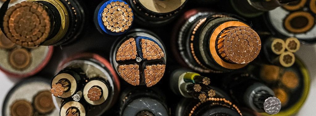

Drain Wire vs Solid Copper Conductor: Making the Right Choice
When specifying cables for a particular application, engineers must weigh several factors:
Mechanical Environment: Will the cable remain stationary, or will it experience frequent movement, vibration, or flexing? Communication cable shielding drain wire in fixed installations can utilize Class 1 solid conductors, while cables for robotic arms, moving machinery, or handheld instruments should specify Class 5 stranded construction.
Reliability Requirements: In mission-critical applications where cable failure is unacceptable, the redundancy offered by stranded conductors provides essential insurance against mechanical failures.
Budget Constraints: For cost-sensitive projects with thousands of cable assemblies, the price difference between solid and fine-stranded conductors can significantly impact project economics.
Installation Practices: Some installation environments subject cables to rough handling during installation. Stranded drain wires better tolerate the inevitable pulling, bending, and occasional abuse that occurs during cable routing.
Drain Wire for EMC Compliance in Real-World Applications
Understanding drain wire installation best practices becomes crucial when examining specific application scenarios:
High-Speed Data Transmission
In Ethernet installations, particularly Category 6A and beyond, maintaining signal integrity at multi-gigabit speeds requires meticulous attention to shielding effectiveness. Shielded twisted pair (STP) cables rely on their drain wires to ensure that the shield remains at ground potential throughout the cable run. Any compromise in drain wire continuity can create ground loops, increase common-mode noise, and potentially cause the installation to fail certification testing.
Industrial Instrumentation and Measurement
Process control environments present unique challenges. Temperature sensors, pressure transducers, and flow meters transmit low-level analog signals that are extremely susceptible to electromagnetic interference from nearby motors, variable frequency drives, and power cables. Shielded cable grounding solutions using robust drain wires are essential for maintaining measurement accuracy.
In these applications, instrumentation cable continuity wire must withstand not only electrical noise but also harsh environmental conditions including temperature extremes, chemical exposure, and mechanical vibration. Class 5 stranded drain wires excel in these demanding circumstances.
Audio and Video Systems
Professional audio installations face interference from numerous sources: lighting dimmers, wireless equipment, computers, and power distribution systems. A properly grounded shield with an effective drain wire prevents audible noise artifacts such as hum, buzz, and clicks from contaminating audio signals.
Similarly, in video systems, electromagnetic interference can manifest as visual artifacts, color distortion, or complete signal loss. Communication cable shielding drain wire implementations ensure clean, interference-free transmission.
Automotive and Transportation
Modern vehicles contain hundreds of electronic control units communicating via CAN bus, LIN bus, and other protocols. The harsh electromagnetic environment—ignition systems, alternators, electric motors—demands robust shielding. Drain wires in automotive cables must withstand constant vibration, temperature cycling from -40°C to +125°C, and years of flexing as harnesses move with engine and suspension components.
Common Problems with Drain Wires and Troubleshooting Solutions
Despite their apparent simplicity, drain wire systems can experience several failure modes:
Problem 1: Drain Wire Continuity Breaks
Symptoms: Intermittent signal quality issues, increased error rates in digital systems, or visible noise in analog signals. Problems may worsen during cable movement or vibration.
Causes: Mechanical stress exceeding the conductor's flex life, improper cable routing creating tight bend radii, or physical damage during installation.
Solution: In stationary installations, repair may involve replacing the damaged cable section. For applications with repetitive flexing, upgrading to Class 5 stranded drain wire construction prevents recurrence. Implement proper cable strain relief and ensure bend radii meet or exceed manufacturer specifications.
Problem 2: Inadequate Grounding Performance
Symptoms: Persistent EMI-related issues despite properly shielded cables, EMC compliance test failures, or ground loop-induced noise.
Causes: Improper termination techniques, high-resistance ground connections, or floating shields where the drain wire isn't connected at one or both ends.
Solution: Verify drain wire termination at all connection points using a low-resistance ohmmeter. Ensure terminations are mechanically secure with proper crimping or soldering. In some installations, grounding at only one end (single-point grounding) may be necessary to prevent ground loops, while others require grounding at both ends. Consult application-specific guidelines for the appropriate grounding strategy.
Problem 3: Corrosion and Oxidation
Symptoms: Gradually increasing ground resistance over time, erratic shielding performance, or complete loss of continuity.
Causes: Moisture ingress, dissimilar metal contact creating galvanic corrosion, or exposure to corrosive atmospheres.
Solution: Use tinned copper drain wires in harsh environments, ensure proper cable sealing and entry techniques, and apply appropriate conformal coatings or environmental protection at termination points. Regular maintenance inspections should include drain wire continuity verification.
Problem 4: Installation-Induced Damage
Symptoms: Immediate or short-term failures following installation, often localized to specific cable segments.
Causes: Excessive pulling tension during cable installation, pinching in cable ties or clamps, or damage from sharp cabinet edges.
Solution: Implement proper installation training emphasizing drain wire vulnerability. Use appropriate pulling tensions (typically not exceeding 25% of the cable's rated tensile strength), avoid over-tightening cable ties, and install protective grommets at cabinet penetrations. Post-installation continuity testing should verify drain wire integrity before system commissioning.
Best Practices for Drain Wire Installation and Grounding
Proper installation techniques are critical for realizing the full benefits of drain wire technology:
Maintain Gentle Bend Radii: Follow manufacturer specifications, typically requiring bend radii of at least 10 times the cable's outer diameter.
Secure Terminations: Use proper crimping tools and techniques or, when soldering, ensure complete solder wetting without excessive heat that might damage nearby insulation.
Verify Continuity: Before energizing systems, use a multimeter to confirm low-resistance continuity between the drain wire and the shield, and from the drain wire to the ground reference point.
Document Grounding Strategy: Clearly specify whether single-point or multi-point grounding is implemented, and ensure consistency across the installation.
Provide Strain Relief: Never allow mechanical stress on the cable to transfer directly to termination points where the drain wire connects to ground.
Conclusion
The humble drain wire represents an elegant engineering solution to the complex challenge of maintaining signal integrity in electromagnetically hostile environments. Whether specified as economical Class 1 solid copper for fixed installations or premium Class 5 fine-stranded construction for dynamic applications, drain wires enable simplified grounding connections while enhancing electromagnetic compatibility and signal reliability.
As electronic systems continue to evolve—with faster data rates, tighter packaging, and harsher operating environments—the importance of proper cable shielding and grounding only increases. Understanding what is a drain wire in shielded cables and implementing appropriate shielded cable grounding solutions ensures your installations meet both performance requirements and regulatory standards.
When selecting cables for your next project, carefully evaluate the mechanical environment, reliability requirements, and cost constraints to choose the optimal drain wire construction. By following installation best practices and implementing proper grounding techniques, you'll maximize system performance while minimizing electromagnetic interference issues that plague poorly designed installations.
How to Reach Us
Get in Touch
SiteMap
Product Catalogue
Festoon Cable
Shore Power Cable




Scan to add us on WeChat