
Dynamic Tensile Load Calculation for Crane Reeling Cables: Why Getting the Maths Wrong Costs You a Fortune
Dynamic tensile load is the most overlooked figure in crane reeling cable design. Learn how to calculate it properly, why static load alone fools engineers, and how to spec cables that survive real-world port, RTG and reclaimer duty.
hongjing.Wang@Feichun
6/12/202611 min read
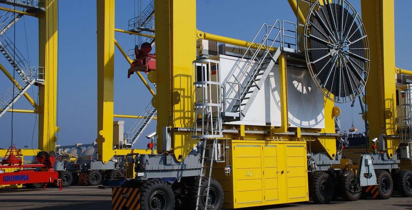
If you've ever stood next to a working RTG and watched the reeling cable snap taut as the crane lurches into motion, you've seen the problem in action. That cable isn't just hanging there carrying its own weight. Every start, stop, and direction change drives a force through it that the spec sheet rarely accounts for. And when the sums are wrong at the design stage, the cable doesn't politely warn you. It stretches, cracks, bird-cages, and fails — usually at the worst possible moment, halfway through a shipping window with a queue of trucks banked up outside the gate.
Here's the uncomfortable truth that doesn't get said often enough at the procurement table: most reeling cable failures aren't a quality problem. They're a calculation problem. The cable was asked to do something it was never rated for, because the dynamic tensile load was either guessed, ignored, or worked out using a static figure that bears no resemblance to how the crane actually runs.
This article walks through how dynamic tensile loads are generated, how to calculate them properly, and why purpose-designed reeling cables matter for port cranes, RTGs, RMGs, stacker reclaimers and ship loaders. It's written for the people who actually have to make the call — engineers, maintenance managers, and procurement folks who'd rather spec it right once than replace it three times.
Why Tensile Load Matters in Reeling Cable Applications
Start with the basics, because the basics are where the trouble begins.
A fixed installation cable lives a quiet life. Once it's pulled into a tray or conduit, it doesn't move again for years. The mechanical demands on it are modest — it needs to carry current, resist the environment, and sit still. Most of its rating is electrical.
A flexible reeling cable lives a completely different life. It's accelerated, decelerated, bent, twisted, and wound onto a reel hundreds or thousands of times a day. Treating these two as interchangeable is the single most common mistake in crane cable specification, and it's the reason "industrial-grade" cables routinely fail in reeling duty within months.
A reeling cable on a working crane copes with several things at once:
Continuous movement as the crane travels back and forth across the yard or quay.
Acceleration and deceleration every time it changes speed — and these are where the real forces live.
Torsional stress as the cable twists slightly with each winding cycle.
Repetitive bending every single time it wraps onto and off the drum.
Of all the parameters an engineer juggles when designing a crane cable system, tensile load is arguably the most critical — and the most frequently underestimated. Get the conductor cross-section right but the tensile rating wrong, and you've built a cable that conducts beautifully right up until it tears itself apart.
Understanding Static Tensile Load
Let's deal with static load first, because it's the figure everyone reaches for — and the figure that quietly misleads.
Static tensile force is simply the tension generated by the cable's own weight when it hangs. No movement, no acceleration. Just gravity pulling down on a length of suspended cable.
Three things determine it:
Cable mass — heavier cables generate more static tension per metre.
Vertical hanging length — the longer the suspended run, the more weight pulls on the top.
Gravity — the constant doing the pulling, at roughly 9.81 m/s².
The basic relationship is straightforward:
Static force (N) = cable mass per metre (kg/m) × suspended length (m) × 9.81 m/s²
A worked example makes it concrete. Say you've got a reeling cable weighing 2.5 kg per metre, with a suspended length of 40 metres during operation. The static tensile load works out to:
2.5 × 40 × 9.81 ≈ 981 N, or just under 1 kN.
So far, so manageable. Most decent reeling cables will shrug off 1 kN without complaint. And this is exactly where engineers get lulled into a false sense of security.
Because here's the catch: static load alone does not represent actual operating conditions. A crane is never just hanging there. It's moving, and movement changes everything. The static figure is the floor, not the ceiling. Spec a cable to its static rating and you've designed for a crane that never switches on.
Dynamic Tensile Load: The Hidden Force Behind Many Cable Failures
Now we get to the figure that actually matters.
Dynamic tensile load is the tension a cable experiences while the crane is accelerating, decelerating or changing direction. The moment a mass changes velocity, an inertial force appears — and that force adds directly to the static load already present.
The governing principle is good old Newton's second law:
Dynamic force (N) = mass (kg) × acceleration (m/s²)
To find the total tensile load on the cable, you combine the static and dynamic components:
Total tensile force = (mass × g) + (mass × a), or more compactly, mass × (g + a)
This is the part that surprises people. The dynamic component scales with acceleration, and crane accelerations are not trivial. Consider where the big forces appear:
Start-up — the crane goes from standstill to travel speed, and the cable feels every bit of that acceleration.
Emergency braking — a hard stop produces deceleration forces that can dwarf normal running loads, sometimes the single highest tension event the cable ever sees.
Direction changes — reversing travel means decelerating to zero and accelerating the other way, two force events back to back.
High-speed travel — faster cranes reach their speed quicker, and quicker means higher acceleration.
Let's extend the earlier example. Same cable, 2.5 kg/m, 40 m suspended — so a moving mass of 100 kg. Suppose the crane accelerates at 1.5 m/s², which is entirely ordinary for a modern travelling crane.
Static component: 100 × 9.81 = 981 N
Dynamic component: 100 × 1.5 = 150 N
That doesn't look dramatic on paper, but acceleration on real cranes — especially during emergency stops — can climb well above 1.5 m/s². Push the deceleration to 5 m/s² during a hard stop and the dynamic component jumps to 500 N, lifting the total well past 1.4 kN from a static figure under 1 kN. On high-speed automated systems with long suspended lengths, the dynamic load can easily exceed the static load outright.
That's the headline: during normal crane operation, dynamic loads frequently exceed static loads. If your cable selection ignored acceleration, you didn't just shave your safety margin — you may have designed past the cable's limit entirely.
Typical Dynamic Conditions in Different Crane Systems
Acceleration and travel speed aren't uniform across crane types. Each application has its own dynamic signature, and understanding yours is half the battle.
RTG Cranes
Rubber-tyred gantries are the workhorses of container yards. They run frequent travel cycles as they shuffle between stacks, typically at medium acceleration, but often over long cable lengths. The combination matters — medium acceleration across a long, heavy suspended run still produces meaningful dynamic tension, and the sheer cycle count drives fatigue.
RMG Cranes
Rail-mounted gantries trade tyres for rails and usually run faster. Higher travel speeds and automated operation mean more frequent, more aggressive acceleration and braking events, with no human operator to ease off. The result is increased dynamic loading — automated cranes don't get tired, and they don't drive gently.
Stacker Reclaimers
These bulk-handling giants are in continuous movement through some of the harshest heavy-duty mining environments going. Add long service life requirements — nobody wants to shut a reclaimer down for a cable swap — and you have an application where underestimating dynamic load is brutally expensive.
Ship Loaders and Ship Unloaders
These machines deal with long cable travel distances and continuous reeling operations, all while exposed to marine conditions. Salt, spray and long suspended lengths combine the dynamic challenge with an aggressive environment, so the tensile calculation has to leave room for both.
The pattern across all four: the faster the operation and the harder the acceleration, the higher the cable tension — and the less forgiving the application is of a sloppy calculation.
The Relationship Between Tensile Load and Cable Design
A cable's ability to survive dynamic tension isn't luck. It's built in, layer by layer.
Flexible copper conductors — fine-stranded, rope-lay conductors flex through millions of cycles without work-hardening and cracking the way solid or coarse-stranded conductors do.
Reinforcement elements — aramid or textile braids run alongside the conductors to carry tensile load, so the copper isn't doing the structural work.
Central support members — a strength member down the core anchors the construction and stops the cable elongating under repeated pull.
Integrated tensile cores — purpose-built load-bearing elements that take the strain the conductors shouldn't.
Outer sheath materials — abrasion-resistant, UV-stable, oil-resistant compounds (commonly PUR) that protect everything inside through bending and winding.
This is precisely why standard industrial cables fail in reeling applications. They were never built to carry tensile load through their structure. Pull on an ordinary cable repeatedly and the copper takes the strain it was never meant to take — and copper, asked to be a load-bearing rope, does not last.
Common Failure Modes Caused by Excessive Dynamic Tension
When the calculation is wrong, the cable tells you in a handful of predictable ways. Learn to read them.
Conductor Stretching
Excessive tension stretches the copper conductors past their elastic limit, leaving permanent elongation. Stretched conductors mean a reduced cross-section, which drives up electrical resistance, which generates more heat, which accelerates ageing — a nasty feedback loop ending in reduced cable lifespan. Once a conductor has stretched, it never recovers.
Insulation Cracking
Repeated overload is mechanical fatigue in action. Tension concentrates stress at weak points — stress concentration — and over thousands of cycles the insulation develops micro-cracks. Those cracks open the door to moisture ingress, short circuits and the risk of electrical faults, which in a marine or dusty environment is a serious safety issue, not just a reliability one.
Bird-Caging
One of the most visually unmistakable failures. Under excessive tension followed by compression — typically from over-tensioning and poor winding — the conductor strands separate and splay outward, forming a shape exactly like a bird cage. It looks dramatic because it is: bird-caging is a sign of severe internal structural damage, and a cable showing it is already well past saving.
Cable Elongation and Structural Deformation
Beyond the conductors, the whole cable can lose its shape. Permanent stretch means loss of dimensional stability, which causes reel winding problems — the cable no longer lays evenly on the drum, which causes crushing and crossovers, which causes more damage. The end result is steadily increasing maintenance requirements as a single root cause cascades into a dozen symptoms.
(In a published version, this is where field photographs of each failure mode earn their place — a bird-caged cable in a photo teaches more than three paragraphs of description.)
Real-World Failure Example: Mining Reclaimer Cable Damage
Theory is fine, but a case study is what makes the message stick.
Project Background
A bulk materials operation at a mine site ran a stacker reclaimer fitted with a reeling cable specified, on paper, for the travel length and current load. The cable met the static requirements comfortably. On a spec sheet, it looked like a sound choice.
Problem Identified
Within months, the operation was seeing premature cable failure — well short of the expected service life. Each failure meant maintenance interruptions to the reclaimer, and every hour of downtime on a reclaimer ripples straight through the materials handling chain.
Root Cause Analysis
The investigation found what these investigations almost always find: the dynamic tension had been underestimated. The original spec considered static load and current capacity but never properly accounted for excessive acceleration during the reclaimer's travel and slewing cycles. The cable's construction simply wasn't designed to carry repeated dynamic loads of that magnitude — an improper cable design for the actual duty.
Corrective Action
Three changes were made together:
A higher tensile-rated cable with an integrated load-bearing core, built for reeling duty rather than general industrial use.
An improved reel configuration to manage winding tension and reduce shock loading.
Optimised cable routing to cut unnecessary bending and side loading.
Results
The outcome was the kind that justifies the engineering work outright: increased service life, reduced downtime, and lower maintenance costs across the board. The replacement cable cost more per metre. It cost far less per year.
Additional Factors That Increase Dynamic Cable Stress
Acceleration is the headline, but it's not the whole story. Several other factors quietly add to the load a cable actually sees.
Incorrect Fleet Angle
The fleet angle is the angle at which the cable approaches the reel. Too steep, and the cable scrapes across guides and lays unevenly, generating side loading and accelerated wear that the tensile calculation never anticipated. A poor fleet angle turns a well-sized cable into an early failure.
Insufficient Bending Radius
Every cable has a minimum bending radius for good reason. Bend it tighter — below the minimum radius — repeatedly, and you fatigue the conductors and sheath far faster than the cycle count alone would suggest. Drum diameter and guide geometry both have to respect that minimum.
Improper Cable Reel Design
The reel itself is part of the load equation. Problems creep in through:
Drum diameter that's too small, forcing tight bends.
Winding geometry that lets the cable cross over itself and crush.
Reel alignment that's off, dragging the cable sideways onto the drum.
Environmental Conditions
The environment compounds everything else. Dust abrades, salt spray corrodes, UV exposure degrades sheaths over time, and extreme temperatures make compounds brittle in the cold or soft in the heat. None of these create tension on their own, but every one of them lowers the load the cable can safely tolerate.
Engineering Guidelines for Safe Reeling Cable Design
So how do you actually get it right? A few practical principles:
Allowable tensile stress limits — know the cable's rated maximum tensile load and never design to brush against it. The rating is a limit, not a target.
Dynamic design margins — always calculate total load as static plus dynamic, using realistic acceleration values, including the worst-case emergency stop.
Safety factors — apply a sensible safety factor (commonly in the order of a few times the calculated peak load) to cover the events your spreadsheet didn't predict.
Cable support methods — use guide rollers, support trolleys or catenary systems to share the load rather than dumping it all on the conductors.
Tension relief systems — spring or counterweight arrangements that smooth out shock loading during acceleration and braking.
Proper cable anchoring — terminate the cable so the strength member carries the pull, not the electrical connections.
The single rule that ties it together: engineering calculations must always include both static and dynamic loading. A design based on static load alone isn't conservative — it's incomplete, and incompleteness is what fails in the field.
How to Select the Right Crane Reeling Cable
When it's time to actually buy the cable, this is the information worth nailing down before you talk to a manufacturer. Walk through each one:
Travel length — how far the crane moves, and the maximum suspended cable length.
Cable weight — mass per metre, which feeds straight into both static and dynamic load.
Operating speed — maximum travel speed in normal duty.
Acceleration rate — both normal and emergency-stop figures; this is the number people forget.
Reel type — motor-driven, spring, or magnetic, and the drum dimensions.
Bending radius — the minimum the reel and routing will impose on the cable.
Environmental conditions — temperature range, UV, salt, dust, chemicals.
Expected service life — how long the cable needs to last before planned replacement.
Hand a cable manufacturer those figures and they can engineer a cable to suit. Hand them a part number and a hopeful expression, and you're trusting that last time's cable matches this time's duty. The difference between those two conversations is the difference between a cable that lasts and one that doesn't.
Conclusion
The thread running through all of this is simple. Dynamic tensile load is the figure most often overlooked during crane cable selection — and it's precisely the figure that determines whether a cable thrives or fails. Static load is easy to calculate and reassuring to look at, which is exactly what makes it dangerous when it's used alone. The crane doesn't run statically. It accelerates, brakes, reverses and repeats, thousands of times a day, and every one of those events drives tension the static figure never captures.
Get the calculation right — account for acceleration, apply proper safety factors, and spec a purpose-built reeling cable rather than a repurposed industrial one — and the payoff is direct: less downtime, longer cable life, and more reliable cranes across ports, mines and bulk materials handling sites. Get it wrong, and you'll pay for it again and again in failed cables and stalled operations. The maths isn't hard. Skipping it is what's expensive.
Expert Summary
The bottom line from the engineering bench: Treat the static tensile load as your starting point, never your answer. On a working crane, the dynamic component — driven by acceleration and, critically, by emergency-stop deceleration — frequently equals or exceeds the static load. The most common failure I see isn't a bad cable; it's a good general-purpose cable asked to do a reeling job it was never built for, on a duty cycle nobody fully calculated.
If you remember three things, remember these. First, always calculate total load as mass × (g + a), and use a realistic worst-case acceleration, not a comfortable average. Second, specify a cable with a dedicated tensile core — let the strength member carry the pull so the copper can stick to carrying current. Third, give your cable manufacturer the full duty picture — travel length, speed, acceleration, reel type, bending radius and environment — before you buy, not after the first failure. Do those three things and you've eliminated the cause behind the overwhelming majority of premature reeling cable failures. The cost of doing the calculation properly is a few hours at a desk. The cost of getting it wrong is measured in shutdowns.
How to Reach Us
Get in Touch
SiteMap
Product Catalogue
Festoon Cable
Shore Power Cable




Scan to add us on WeChat