

Electric Field Distribution Analysis: Conductors and Non-Shielded Cables on a Ground Plane
Explore the electric field distribution around conductors and non-shielded cables. Learn how ground planes, dielectrics, and insulation impact EMI risks and field symmetry.
hongjing.wang@Feichun
12/22/202510 min read
Introduction
In electrical engineering and cable system design, understanding electric field distribution is fundamental to creating safe, efficient, and interference-free installations. The invisible forces surrounding conductors and cables can significantly impact system performance, signal integrity, and electromagnetic compatibility. When engineers overlook these field patterns, the consequences can range from minor signal degradation to catastrophic system failures in sensitive applications.
Electric field distribution refers to the spatial arrangement and intensity of electric forces surrounding charged conductors. These fields don't exist in isolation—they interact with surrounding materials, nearby conductive surfaces, and the environment itself. This article examines two critical scenarios that every cable system designer must understand: a conductor positioned on a ground plane within a uniform dielectric medium, and a non-shielded cable resting on a ground plane. By analyzing these configurations, we can identify the factors that influence electromagnetic interference (EMI) risks and develop strategies for optimal cable systems design.
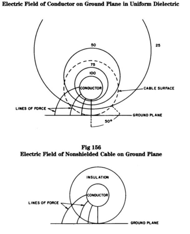

Scenario 1: Conductor on a Ground Plane in Uniform Dielectric
Configuration and Setup
The first scenario presents an idealized yet instructive case: a single conductor positioned above a ground plane, completely surrounded by a uniform dielectric material. This configuration serves as a baseline for understanding fundamental field behavior. The conductor carries electrical potential, creating an electric field that radiates outward in all directions. The ground plane, maintained at zero potential, serves as a reference and terminus for field lines.
The uniform dielectric medium—whether air, polyethylene, or another insulating material—provides consistent permittivity throughout the space. This consistency is crucial because any variation in dielectric properties would distort the field pattern and create unpredictable behavior.
Electric Field Characteristics
In this configuration, electric field lines emerge perpendicularly from the conductor surface and terminate perpendicularly on the ground plane. The symmetrical electric field lines demonstrate a predictable pattern: they spread radially from the conductor, with density decreasing as distance increases. This relationship follows the inverse-square law, where field strength diminishes proportionally to the square of the distance from the source.
Near the conductor surface, field strength reaches its maximum intensity. This concentration of field lines indicates the highest electrical stress in the system. As we move away from the conductor, the field lines spread out, reducing the field intensity. The spacing between adjacent field lines visually represents this strength gradient—closely packed lines indicate strong fields, while widely spaced lines indicate weaker fields.
The uniform dielectric ensures that these field lines maintain smooth, predictable curves without sudden deflections or discontinuities. This behavior is desirable in cable design because it indicates controlled energy distribution and minimal potential for localized stress concentrations that could lead to dielectric breakdown.
The Role of Dielectric Materials
Dielectric materials serve multiple functions in this configuration. First, they provide electrical insulation, preventing current leakage between the conductor and ground plane. Second, they influence the capacitance of the system—higher permittivity materials increase capacitance, which can be either beneficial or detrimental depending on application requirements.
Most importantly for our analysis, uniform dielectric materials ensure consistent field distribution. When the dielectric constant remains constant throughout the medium, electric field lines follow predictable paths determined purely by geometry and charge distribution. This predictability allows engineers to calculate field strength at any point, assess voltage stress on insulation, and design systems with appropriate safety margins.
Practical Implications
This idealized scenario approximates real-world situations such as overhead transmission lines, busbars in air, or conductors embedded in solid dielectric materials. Understanding this baseline behavior helps engineers predict how fields will behave in more complex configurations and identify deviations that indicate potential problems.
Scenario 2: Electric Field of a Non-Shielded Cable
Configuration and Field Behavior
The second scenario introduces complexity that reflects common industrial cable installations: a conductor surrounded by insulation but lacking metallic shielding, positioned on or near a ground plane. This configuration is typical in power distribution, building wiring, and many industrial applications where cost constraints or perceived low EMI risk lead to the use of non-shielded cables.
Unlike the uniform dielectric case, here we have distinct material layers: the conductor core, insulation material (typically PVC, rubber, or cross-linked polyethylene), air or other filling medium, and the ground plane. Each interface between materials with different dielectric constants creates a boundary condition that affects field line behavior.
Electric field lines originate from the conductor and pass through the insulation layers. However, the insulation penetration doesn't stop the fields—they continue into the surrounding air and eventually terminate on the ground plane. This external field propagation represents a fundamental difference from shielded configurations and is the source of many electromagnetic interference challenges.
Asymmetrical Field Distribution
The proximity to the ground plane creates an asymmetrical field distribution that departs significantly from the symmetrical pattern seen in Scenario 1. Field lines on the side of the cable facing the ground plane are shorter and more densely packed, indicating higher field intensity in this region. Conversely, field lines on the opposite side extend further into space before curving down toward the ground plane.
This asymmetry has several important consequences. First, it creates uneven electrical stress distribution in the insulation, with the highest stress occurring on the ground-facing side. Over time, this localized stress can accelerate insulation aging and increase the likelihood of failure in that region. Second, the asymmetrical field distribution caused by the proximity to the ground plane makes the cable's electromagnetic behavior position-dependent—moving the cable closer to or further from the ground plane significantly alters its electrical characteristics.
Electromagnetic Interference Risks
The uncontained electric fields surrounding non-shielded cables represent the primary source of electromagnetic interference in such installations. As the voltage on the conductor varies (particularly in AC power applications), the electric field strength fluctuates correspondingly. These time-varying fields can couple capacitively to adjacent conductors, inducing unwanted voltages in nearby signal cables or sensitive electronic equipment.
The external propagation of fields means that the cable acts as both a source and a receptor of interference. Not only does it radiate fields that can affect nearby equipment, but it is also susceptible to picking up interference from external sources. This bidirectional vulnerability makes non-shielded cable installations particularly problematic in electromagnetically noisy environments.
The Limitations of Insulation Alone
Insulation materials provide essential electrical isolation and mechanical protection, but they cannot contain electric fields the way metallic shielding can. Insulation guides the field and reduces its intensity through its dielectric properties, but field lines inevitably penetrate through and beyond the insulation boundary. The insulation's effect is to reduce field strength compared to a bare conductor, but this reduction is often insufficient in sensitive environments.
The dielectric constant of the insulation material influences how fields behave at the boundary. Higher dielectric constant materials attract more field lines into the insulation itself, reducing the external field somewhat. However, even high-permittivity insulation cannot prevent all external field propagation—only a conductive shield can accomplish that.


Key Observations & Comparative Analysis
Impact of the Ground Plane
The ground plane exerts a profound influence on electric field distribution in both scenarios. Acting as an equipotential surface at zero volts, it serves as an attractive terminus for electric field lines. This attraction fundamentally alters the field pattern, pulling field lines downward and creating asymmetry whenever a conductor is positioned near the ground plane.
The degree of asymmetry depends on the conductor-to-ground plane separation. As this distance decreases, the asymmetry becomes more pronounced, with field lines increasingly concentrated on the ground-facing side. This effect has practical implications for cable spacing requirements and installation practices.
Shielded vs. Non-Shielded Cables: A Critical Distinction
The comparison between these two scenarios highlights the fundamental difference between insulation and shielding. Insulation is a dielectric material that provides electrical isolation but allows electric fields to penetrate through. Shielding, typically constructed from metallic braid, foil, or conduit, provides a conductive barrier that electric field lines cannot penetrate under static or low-frequency conditions.
In a shielded cable, electric field lines originating from the conductor terminate on the interior surface of the shield rather than propagating externally. The shield, when properly grounded, carries induced currents that generate fields opposing and canceling the conductor's external field. This containment dramatically reduces both emitted and susceptible EMI.
Non-shielded cables lack this containment mechanism. Their fields extend into the surrounding environment, creating EMI risks that scale with voltage, frequency, and proximity to sensitive equipment. The missing component in Scenario 2—metallic shielding—represents the single most effective intervention for reducing electromagnetic interference in cable systems.
Understanding EMI Implications
Comparing the "clean" field of the uniform dielectric case against the "leaky" field of the non-shielded cable illuminates the nature of electromagnetic interference. In the first scenario, fields remain predictable and contained within the dielectric medium. In the second, fields propagate unpredictably into the surrounding environment, where they can interact with other conductors, equipment, and systems.
The frequency content of signals carried by the cable significantly affects EMI severity. Low-frequency power cables generate primarily electric field coupling, while high-frequency signal cables generate both electric and magnetic field coupling. The uncontained fields from non-shielded cables become increasingly problematic as signal frequency increases, making shielding nearly mandatory for high-speed data transmission.
Engineering Applications and Implications
Designing for Sensitive Environments
Certain applications demand stringent control of electromagnetic emissions and immunity. Medical facilities, where patient monitoring equipment must detect microvolt-level biological signals, cannot tolerate interference from power cables. Industrial control systems, where sensor cables carry millivolt-level signals in proximity to high-current motor cables, require careful design to prevent cross-talk. Aerospace and military applications, where electromagnetic compatibility is mission-critical, mandate comprehensive shielding strategies.
In these sensitive environments, shielded cables are not optional—they are essential. The engineer must specify cables with appropriate shield coverage (typically 90% or greater for critical applications), ensure proper shield grounding, and maintain shield continuity through connectors and terminations. The additional cost of shielded cables is minimal compared to the cost of interference-induced system failures or regulatory non-compliance.
Material Selection and Cable Efficiency
The importance of choosing the right dielectric materials cannot be overstated. Dielectric constant, loss tangent, breakdown strength, thermal stability, and mechanical properties all influence cable performance. For uniform field distribution, consistency in dielectric properties throughout the cable is crucial.
Cross-linked polyethylene (XLPE) offers excellent electrical properties with low dielectric constant and loss, making it suitable for high-voltage power cables. Polytetrafluoroethylene (PTFE) provides superior high-frequency performance and temperature stability for critical signal applications. Polyvinyl chloride (PVC) offers cost-effective insulation for general-purpose applications where electrical demands are modest.
The synergy between proper dielectric selection and appropriate shielding creates cable efficiency—the cable performs its intended function while minimizing energy loss, maintaining signal integrity, and controlling electromagnetic emissions. This efficiency translates directly to system reliability and operational cost savings.
Cost-Benefit Analysis: When to Shield
Not every application requires shielded cables. In residential wiring, where cables are separated from sensitive electronics and EMI tolerance is high, non-shielded cables serve adequately at lower cost. In industrial power distribution within electromagnetically quiet zones, unshielded cables may suffice. The key is conducting a proper risk assessment that considers:
Voltage and current levels carried by the cable
Frequency content of signals (power, control, or data)
Proximity to sensitive equipment or other cables
Ambient electromagnetic environment
Regulatory requirements and industry standards
Consequences of interference-induced failures
When analysis reveals moderate to high EMI risks, the incremental cost of shielding is justified by the protection it provides. When risks are demonstrably low, non-shielded cables offer economic advantages without compromising system integrity.
Common Cable Problems and Solutions
Problem 1: Unexpected EMI in Presumed Low-Interference Environments
Question: Why does electromagnetic interference appear in installations where non-shielded cables were deemed acceptable during design?
Solution: EMI problems often emerge when initial assumptions prove incorrect. Facilities expand, adding new equipment that alters the electromagnetic environment. Cable routing changes during installation, bringing cables into closer proximity than planned. Equipment upgrades introduce higher frequencies that couple more effectively than original lower frequencies.
The solution requires systematic troubleshooting: identify interference sources and victims, measure actual field strengths and coupling paths, and implement targeted mitigation. This might include retrofit shielding on critical cables, increased separation distances, installation of ferrite cores to reduce high-frequency coupling, or filtering at equipment interfaces. Prevention through conservative initial design—using shielded cables when EMI risk is uncertain—proves more cost-effective than post-installation remediation.
Problem 2: Partial Shield Grounding and Field Leakage
Question: Why do shielded cables sometimes fail to prevent electromagnetic interference despite proper specification?
Solution: Shield effectiveness depends critically on proper grounding. A floating shield (ungrounded at both ends) provides minimal benefit, as it cannot carry the induced currents necessary to cancel external fields. Grounding only one end helps with low-frequency electric field shielding but proves inadequate at higher frequencies where shield currents must flow.
For most applications, shields should be grounded at both ends to maximize effectiveness. However, this creates ground loops that can cause other problems in sensitive systems. Advanced techniques like shield grounding through capacitors (providing high-frequency ground path while blocking low-frequency ground loops) or careful ground potential management may be required. Additionally, shield damage during installation—even small breaks in braid coverage—can significantly reduce effectiveness.
Problem 3: Insulation Degradation on Ground-Facing Surfaces
Question: Why does cable insulation fail preferentially on the side facing ground planes or conductive surfaces?
Solution: As discussed in the asymmetrical field distribution section, proximity to ground planes concentrates electric field stress on the conductor side nearest the ground. This localized stress accelerates insulation aging through multiple mechanisms: partial discharge in voids or contamination, electrochemical treeing in moisture-contaminated insulation, and thermal stress from localized heating.
Prevention requires multiple approaches: maintain adequate separation between cables and ground planes (typically specified in cable installation standards), use cables with higher voltage ratings than minimum requirements to reduce electrical stress, ensure insulation is moisture-sealed to prevent contamination, and implement periodic inspection or monitoring in critical applications. For existing installations showing premature aging, increasing separation distance or adding supplemental insulation barriers can extend service life.
Conclusion
Understanding electric field distribution around conductors and cables is fundamental to designing reliable, interference-free electrical systems. The two scenarios examined—a conductor in uniform dielectric and a non-shielded cable on a ground plane—illustrate how ground planes and insulation modify electric field patterns, creating asymmetry and external field propagation that must be managed.
The analysis reveals that while insulation provides essential electrical isolation, only metallic shielding can truly contain electric fields and prevent electromagnetic interference. Ground planes significantly influence field distribution, creating asymmetry that affects both electrical stress distribution and EMI characteristics. Material selection, particularly of dielectric materials, plays a crucial role in maintaining uniform field distribution and cable efficiency.
For engineers and system designers, the key takeaway is clear: analyze field distribution to predict EMI risks and ensure system reliability. Use shielded cables in sensitive environments where interference cannot be tolerated. Select appropriate dielectric materials to maintain predictable field patterns. Consider the impact of ground planes and conductive surfaces during cable routing. When in doubt, prioritize shielding over cost savings—the expense of preventing interference is minimal compared to the cost of remediation or system failure.
As electronic systems become increasingly sensitive and electromagnetic environments grow more complex, rigorous attention to electric field distribution in cable systems design will only become more critical. Engineers who master these principles and apply them systematically will deliver systems that perform reliably in the most demanding applications, free from the electromagnetic interference that plagues poorly designed installations.
How to Reach Us
Get in Touch
SiteMap
Product Catalogue
Festoon Cable
Shore Power Cable




Scan to add us on WeChat