

EMC Cable vs VFD Cable: Complete Guide to Differences, Selection, and Size Calculation for Motor Control Systems
Learn the key differences between EMC and VFD cables, how to calculate cable size, voltage drop formulas, and select the right shielded cable for your motor control system.
hongjing.Wang@Feichun
12/17/202510 min read
Introduction
When designing or maintaining motor control systems, one of the most critical decisions involves selecting the appropriate cable. Many engineers and technicians face confusion when choosing between EMC cables and VFD cables, often using these terms interchangeably. However, understanding what is the difference between EMC and VFD cable is essential for ensuring system reliability, minimizing electromagnetic interference, and preventing costly operational failures. This comprehensive cable selection guide for motors will clarify the distinct characteristics of each cable type, provide detailed sizing calculations, and help you determine the right shielded cable for your specific application.
What is EMC Cable? (Electromagnetic Compatibility Cable)
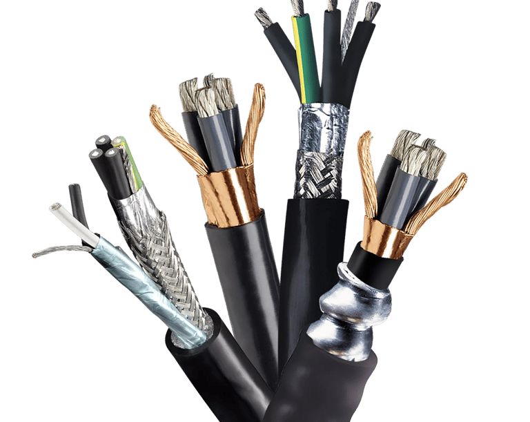
An EMC cable, or electromagnetic compatibility cable, is specifically designed to reduce electromagnetic interference (EMI) in electrical systems. The primary function of these cables is to contain unwanted electrical energy within the cable itself and prevent it from radiating into surrounding equipment or being affected by external electromagnetic fields. This EMI reduction capability makes EMC cables essential in environments where sensitive electronic equipment operates in close proximity.
Shielding Materials and Construction
The effectiveness of how EMC cable reduces electromagnetic interference depends heavily on its shielding construction. EMC cables incorporate various shielding materials, each offering different levels of protection:
Copper Shielding: Copper shielded cables provide excellent conductivity and superior EMI protection. The copper layer effectively captures and redirects electromagnetic energy to ground, making it ideal for high-interference environments.
Aluminum Shielding: Aluminum foil shielding offers a cost-effective solution with good EMI protection for moderate interference applications. While slightly less conductive than copper, aluminum provides adequate shielding for many industrial applications.
Combination Shielding: Many modern EMC cables employ both copper braid and aluminum foil layers, creating multiple barriers against electromagnetic interference. This hybrid approach balances cost with performance.
How EMC Cables Prevent EMI
Understanding how to prevent electromagnetic interference in cables requires knowledge of the shielding mechanism. EMC cables work by creating a conductive path that intercepts electromagnetic waves before they can radiate from or penetrate into the cable conductors. The shield must be properly grounded to provide an effective return path for the intercepted interference. The EMI shielding effectiveness is measured in decibels (dB), with higher values indicating better protection. Quality EMC cables typically provide 60dB or more attenuation across critical frequency ranges.
What is VFD Cable? (Variable Frequency Drive Cable)
A VFD cable, or variable frequency drive cable, serves a specialized purpose in motor speed control systems. When considering what VFD cable is used for, it's designed specifically to handle the unique electrical characteristics generated by variable frequency drives, which convert fixed-frequency AC power into variable-frequency output to control motor speed.
VFD Cable Construction Features
VFD motor cables incorporate several distinctive construction features that differentiate them from standard power cables:
Thicker Insulation Requirements: The question of why VFD cables need thicker insulation relates to the high-frequency voltage spikes generated by VFD switching circuits. These voltage transients, often reaching several times the nominal voltage, require robust insulation to prevent dielectric breakdown. VFD cable insulation is typically rated for 600V or higher, even when used in 480V systems, providing a safety margin against voltage spikes.
Enhanced Shielding: High-frequency cables for variable frequency drives employ multiple shielding layers to contain the electrical noise generated during PWM (Pulse Width Modulation) switching. This enhanced shielding prevents interference with nearby control circuits and communication systems while protecting the motor from voltage reflections.
Handling High-Frequency Voltage and Current
VFD systems generate carrier frequencies ranging from 4kHz to 16kHz or higher, creating significant electrical noise. High-frequency voltage cable protection in VFD systems requires cables that maintain their insulation integrity under rapid voltage transitions. The cable capacitance and inductance must also be carefully controlled to minimize voltage reflections that can damage motor windings. Electrical noise reduction in VFD systems depends on properly designed and installed VFD cables that provide a low-impedance path for high-frequency currents back to the drive.

Key Differences Between EMC Cable and VFD Cable
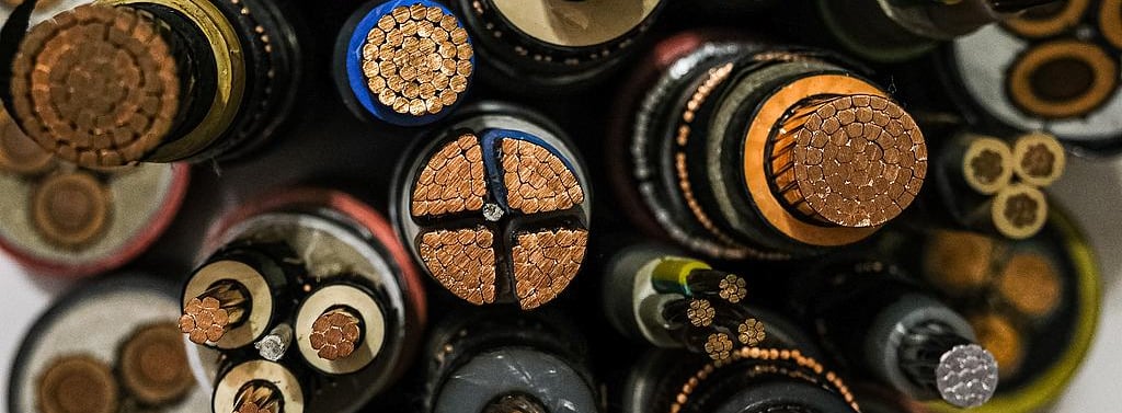
Understanding the main differences between EMC cable and VFD cable is crucial for proper cable selection. While both are shielded cable types, their design priorities differ significantly.
EMC cables are designed primarily for electromagnetic interference reduction through strategic shielding layers, while VFD cables are engineered specifically for variable frequency drive applications. EMC cables typically feature standard insulation thickness and moderate shielding effectiveness, making them suitable for general equipment protection across various industries. VFD cables, by contrast, incorporate thicker insulation and enhanced shielding to handle the unique challenges of high-frequency voltage and current generation from variable frequency drives.
The key distinction lies in their intended applications: EMC cables protect against external electromagnetic noise in control circuits and general equipment, whereas VFD cables specialize in motor control systems where electrical noise mitigation is critical for proper motor operation. When deciding when to use EMC vs VFD cable, consider that VFD cables must withstand not only EMI but also the electrical stress of rapid voltage transitions and high dv/dt (rate of voltage change).
How to Calculate VFD Cable Size
Proper VFD cable sizing is essential for system reliability and efficiency. This VFD cable sizing guide step by step will walk you through the calculation process.
Step 1: Determine Full-Load Current
Begin by identifying how to find full-load current on motor nameplate. The motor nameplate displays the full-load amperage (FLA) at the rated voltage. This value represents the maximum continuous current the motor draws under full load conditions. Always refer to the motor specification sheet for cable sizing to ensure accuracy.
Step 2: Calculate Acceptable Voltage Drop
What is acceptable voltage drop for VFD systems? Industry standards recommend maintaining voltage drop below 2-3% of the system voltage to ensure proper motor performance. For a 480V system, this translates to a maximum voltage drop of 9.6V to 14.4V (480V × 2% = 9.6V; 480V × 3% = 14.4V). Excessive voltage drop leads to reduced motor torque, overheating, and inefficient operation. The 2-3% range provides optimal balance between cable cost and motor performance.
Step 3: Apply the Voltage Drop Formula
The voltage drop calculation for 480V motors uses this fundamental formula:
Voltage Drop = (2 × Distance × Current) / (Conductor Size × Voltage Level)
Where:
Distance is the one-way cable length in feet
Current is the full-load current in amperes
Conductor Size is measured in circular mils (CM)
Voltage Level is the system voltage
When considering how to use voltage drop formula for VFD cables, remember that the factor of 2 accounts for the round-trip current path (conductor and return path).
Step 4: Practical Example
Let's work through a VFD cable sizing example for 50 amps with a 50-foot cable run to demonstrate how to size cable for 50 foot run:
Given:
Motor current: 50 amps
Distance: 50 feet
System voltage: 480V
Target voltage drop: 2.5% (12V)
Using the formula:
Voltage Drop = (2 × 50 ft × 50 Amps) / (Conductor Size × 480V)
For a 2.5% voltage drop (12V):
12V = 5,000 / (Conductor Size × 480)
Conductor Size = 5,000 / (12 × 480) = 5,000 / 5,760
This calculation indicates that a 10 AWG copper conductor would be appropriate for this application, providing adequate current capacity while maintaining voltage drop within acceptable limits.
Selecting Appropriate Cable for Application
How to select VFD cable for specific applications involves considering ambient temperature, installation method (conduit, tray, or direct burial), and whether multiple cables run together. Always consult the National Electrical Code (NEC) or local electrical codes for specific derating factors. Choosing the right cable size for motor control also requires verifying that the selected cable meets the VFD manufacturer's recommendations for maximum cable length to avoid motor insulation damage from voltage reflections.
Important Note: The calculations provided serve as a guideline for cable sizing. In practice, the best cable size and voltage drop calculation may vary based on specific application requirements, environmental conditions, and manufacturer specifications. Always consult with a cable specialist or VFD manufacturer to ensure optimal cable selection for your particular installation.
How to Calculate EMC Cable Size
The process for how to calculate EMC cable size differs from standard power cable calculations because it emphasizes electromagnetic shielding performance alongside current-carrying capacity.
Step 1: Determine Full-Load Current
Similar to VFD cable sizing, start by identifying how to determine cable current rating from equipment specifications. Review the equipment nameplate or technical documentation to establish the maximum continuous operating current. EMC cables must be rated for at least 125% of the continuous load current to provide adequate safety margin.
Step 2: Identify EMI/RFI Exposure Level
Understanding how to identify RFI exposure level requires analyzing the electromagnetic environment. Measure or estimate the frequency range of potential interference sources, typically between 150kHz to 30MHz for most industrial applications. Radio frequency interference (RFI) cable protection requirements depend on the proximity and power of nearby RF sources such as welding equipment, radio transmitters, or high-power switching devices. EMI protection standards for cables are defined by international standards including IEC 61000 and MIL-STD-461.
Step 3: Determine Required Attenuation
What attenuation is needed for cable shielding? The required 60dB shielding effectiveness represents 99.9% reduction in electromagnetic energy transmission. Higher attenuation values provide greater protection. Calculate the required attenuation by measuring the ambient EMI level and subtracting the maximum permissible interference at sensitive equipment inputs.
Step 4: Selection Criteria
This EMC cable selection criteria checklist ensures comprehensive evaluation:
Verify current rating exceeds equipment requirements by 25%
Confirm shielding attenuation meets or exceeds calculated requirements across relevant frequencies
Check cable flexibility and bend radius for installation constraints
Ensure shield termination hardware is compatible with grounding requirements
Validate environmental ratings (temperature, chemical resistance, UV exposure)
How to verify cable shielding specifications involves reviewing manufacturer test data showing attenuation performance across the frequency spectrum. Reputable manufacturers provide detailed shielding effectiveness graphs showing performance from 10kHz to 10GHz.
Practical Example
For an EMC cable sizing example for 20 amps serving sensitive instrumentation:
Given:
Equipment current: 20 amps
EMI exposure: 150kHz-30MHz range
Required attenuation: 60dB minimum
Installation: Industrial environment with moderate interference
Selection:
Choose 12 AWG conductor (rated 25 amps, providing 125% safety factor)
Specify dual-shield construction (aluminum foil + copper braid)
Verify manufacturer certification for ≥60dB attenuation from 150kHz-30MHz
Select cable with stranded conductors for flexibility
Important Consideration: This example provides a framework for EMC cable selection. In real-world applications, the optimal cable size and EMI protection level may vary significantly based on specific environmental conditions, equipment sensitivity, and interference sources. Professional consultation with cable experts or EMI specialists is strongly recommended to ensure proper cable selection for your specific application needs.
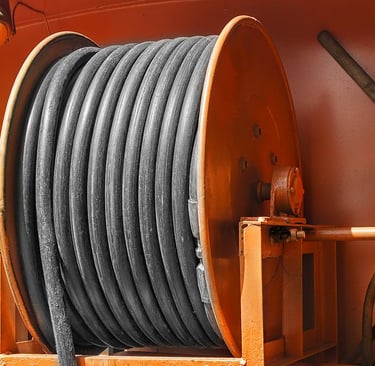
Cable Selection Guide: When to Use Each Type
Choosing the correct cable for your application requires understanding the operational environment and electrical characteristics.
Applications for EMC Cables
Best applications for EMC cables include:
Control Circuits: PLC (Programmable Logic Controller) wiring, sensor connections, and instrumentation signals benefit from EMC cable for signal protection. These low-voltage circuits are particularly susceptible to electromagnetic interference that can cause false triggering or signal corruption.
Data Transmission Lines: Serial communication systems (RS-485, RS-232), Ethernet networks in industrial settings, and fieldbus protocols require EMC cables to maintain signal integrity. The shielding prevents crosstalk between adjacent cables and protects against external noise sources.
Sensitive Measurement Systems: Thermocouple circuits, strain gauge connections, and precision analog signals require the EMI protection that EMC cables provide. Even minor interference can introduce measurement errors in these applications.
Applications for VFD Cables
When to use VFD cables becomes clear in these scenarios:
Motor Control Systems: The primary application is connecting VFD output to three-phase motors. VFD cables for motor control applications must handle PWM waveforms without degradation or excessive EMI radiation. Use VFD-rated cables for all motor connections between the drive and motor terminals.
Variable Speed Drive Systems: Applications including HVAC systems, conveyor drives, pump controls, and elevator motors all benefit from properly specified VFD cables. These systems generate substantial high-frequency noise that VFD cables are specifically designed to contain.
Long Cable Runs: When motor cables exceed 50 feet, voltage reflections become particularly problematic. VFD cables with controlled impedance characteristics minimize reflected wave magnitude, protecting motor insulation from premature failure.
Key Considerations for Cable Installation
Proper installation is as important as correct cable selection. Following best practices for cable installation ensures optimal performance.
Consulting with Experts
When to consult a cable expert includes situations involving:
Unusual environmental conditions (extreme temperatures, corrosive atmospheres, explosive environments)
Critical applications where downtime costs are substantial
Complex systems with multiple interference sources
Installations requiring custom cable specifications
Professional cable sizing services can provide detailed calculations considering all variables, including harmonic content, ambient conditions, and future expansion plans.
Application-Specific Requirements
Custom cable sizing for specific applications recognizes that no two installations are identical. Application requirements for cable selection include:
Installation Method: Cables installed in conduit experience different thermal conditions than those in cable trays or direct burial. Conduit installations require derating for heat buildup.
Ambient Temperature: High ambient temperatures reduce cable current-carrying capacity. Apply appropriate correction factors from NEC tables.
Grouping Effects: Multiple cables installed together generate mutual heating. Derating factors must account for the number of current-carrying conductors.
Future Expansion: Size cables to accommodate anticipated load growth without requiring replacement.
Common Cable Problems and Solutions
Problem 1: Motor Insulation Failure in VFD Applications
Symptoms: Premature motor winding insulation breakdown, leading to ground faults or phase-to-phase shorts.
Cause: Using standard power cable instead of VFD-rated cable creates excessive voltage reflections. When cable impedance mismatches the motor impedance, reflected waves can double the voltage stress on motor windings.
Solution: Replace standard cables with properly rated VFD cables. For existing installations with cable lengths exceeding 50 feet, install output reactors or dv/dt filters at the VFD output to reduce voltage rise time and reflection magnitude.
Problem 2: EMI Affecting Control Circuits
Symptoms: Erratic PLC behavior, communication errors, or false sensor readings near power cables.
Cause: Inadequate separation between power and control cables, or using unshielded cables in high-EMI environments.
Solution: Install dedicated EMC cables for all control wiring. Maintain minimum separation distances (typically 12 inches) between power and control cables. When crossing is unavoidable, cross at 90-degree angles to minimize coupling. Ensure shield terminations are properly grounded at both ends for control cables, or at one end for instrumentation cables to prevent ground loops.
Problem 3: Excessive Voltage Drop
Symptoms: Motor overheating, reduced torque, VFD fault codes indicating undervoltage or overcurrent conditions.
Cause: Undersized cables creating voltage drop exceeding 3% of system voltage.
Solution: Recalculate cable size using the voltage drop formula provided earlier. For existing installations where cable replacement is impractical, consider increasing system voltage (if equipment permits) or reducing cable length by relocating equipment. In some cases, installing a step-up/step-down transformer near the motor can compensate for voltage drop.
Problem 4: Shield Termination Issues
Symptoms: EMI problems persist despite using shielded cables, or ground fault current flowing through shields.
Cause: Improper shield grounding creates ineffective EMI protection or hazardous ground loops.
Solution: For VFD motor cables, ground the shield at the drive end only using 360-degree termination methods. This prevents circulating currents while maintaining EMI protection. For EMC cables in control systems, ground at both ends if ground potential difference is minimal, or at one end for long cable runs to prevent ground loops.
Conclusion
Selecting between EMC cables and VFD cables requires understanding their fundamental differences and intended applications. EMC cables excel at protecting sensitive control and communication circuits from electromagnetic interference through effective shielding, while VFD cables are engineered to withstand the demanding electrical environment created by variable frequency drives with their thicker insulation and enhanced shielding capabilities.
Proper cable sizing involves more than simple ampacity calculations. For VFD applications, voltage drop calculations ensure adequate voltage reaches the motor, while EMC cable selection requires evaluating shielding effectiveness against measured or anticipated interference levels. Both cable types play critical roles in modern industrial systems, and choosing the right cable for your system prevents costly downtime, equipment damage, and operational inefficiencies.
Key takeaways for EMC and VFD cable selection include: always verify manufacturer specifications, calculate voltage drop for power applications, assess EMI exposure levels for sensitive circuits, follow proper installation practices, and consult with cable specialists for complex or critical applications. By applying the principles and calculations outlined in this guide, you can confidently select and size cables that will provide reliable, long-term performance in your motor control and automation systems.
How to Reach Us
Get in Touch
SiteMap
Product Catalogue
Festoon Cable
Shore Power Cable




Scan to add us on WeChat