
F-(N)TSWOEU I 5 KV Medium Voltage Semi-Flexible Cable for Conveyor Belts & Submersible Pump Applications | Industrial Power Cable
5 KV medium voltage semi-flexible cable for conveyor systems, cable booms & submersible pumps. Oil & UV resistant EPR insulation for demanding industrial applications.
hongjing.Wang@Feichun
10/29/202515 min read
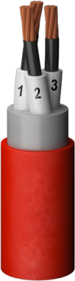
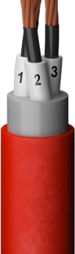
Introduction & Product Overview
The F-(N)TSWOEU I 5 KV represents a specialized class of medium voltage semi-flexible power cables engineered specifically for demanding industrial and mining applications. This cable series is designed to withstand extreme environmental conditions while maintaining reliable electrical performance in critical power distribution scenarios.
What is a 5 KV Medium Voltage Cable Used For?
A 5 KV medium voltage cable serves as the backbone of industrial power distribution systems, particularly in applications requiring robust electrical connections in challenging environments. The F-(N)TSWOEU cable designation indicates a semi-flexible medium voltage cable for conveyor systems, material handling equipment, and submersible pump installations where traditional fixed cables would fail under continuous mechanical stress.
This industrial cable is specifically designed for laying alongside fixed and shiftable conveyor units, material handling equipment with continuous movement (such as cable booms or connections between upper and lower car assemblies), and submersible pump connections in deep well and underwater installations. The mining cable variant excels in strip mining and open-pit mining operations where cables must endure constant flexing, abrasion, and exposure to harsh chemicals and environmental conditions.
The semi-flexible power cable construction allows for applications requiring moderate flexibility without the complexity of fully flexible trailing cables, making it ideal for semi-fixed installations where occasional repositioning occurs but constant reeling is not required.
Key Features & Technical Specifications
The F-(N)TSWOEU I 5 KV cable series offers comprehensive medium voltage cable specifications designed for reliability and longevity in industrial settings.
Voltage Ratings and Electrical Parameters
The 5 KV cable specifications cover a range of voltage ratings to accommodate various application requirements. The cable operates with a rated voltage from 1.8/3 kV (Um 3.6 kV) up to 5 KV capabilities, with test voltage capacity reaching 11kV for the 3.6/6 kV configuration. This robust electrical design ensures safe operation with adequate safety margins for voltage transients common in industrial environments.
Conductor Construction
The conductor specifications feature finely stranded bare copper constructed to Class 5 flexibility standards, ensuring optimal current carrying capacity while maintaining sufficient flexibility for semi-fixed installations. Conductor sizes range from 25 mm² to 300 mm², accommodating power transmission requirements from moderate to high-capacity industrial loads. The bare copper construction provides superior electrical conductivity while the fine stranding enables the semi-flexible characteristics essential for applications involving periodic movement.
EPR Rubber Insulated Medium Voltage Cable Specifications
The EPR insulation cable construction represents a critical component of the cable's performance envelope. The insulation system consists of multiple layers: a semi-conductive EPR inner layer surrounds the conductor, followed by the primary EPR rubber insulation manufactured to specialized compound specifications (3GI3). An outer semi-conductive NBR easy-strip layer completes the insulation system, facilitating clean termination procedures during installation.
What Temperature Range Does 5 KV Cable Operate In?
The cable technical specifications define operational temperature ranges critical for application planning. For fixed installations, the ambient temperature range extends from –40°C to +80°C, demonstrating exceptional cold weather performance and high-temperature resistance. During flexible operation, the range narrows to –25°C to +60°C, accounting for the increased mechanical stress during movement. The maximum conductor temperature during normal operation reaches 90°C, while short circuit conditions permit brief excursions up to 250°C without permanent damage to the insulation system.
Mechanical Properties and Sheathing
The outer sheath consists of chlorinated polyethylene (CPE/CM), specifically formulated for chemical resistance, mechanical protection, and environmental durability. The bending radius specifications are carefully defined to prevent insulation damage: 6× the cable diameter for fixed installation and 10× the diameter for flexible operation. These cable bending radius specifications ensure long service life by preventing excessive stress on the insulation system during installation and operation.
Environmental & Chemical Resistance
Industrial environments subject cables to numerous environmental stressors that would quickly degrade standard power cables. The F-(N)TSWOEU series addresses these challenges through carefully selected materials and construction techniques.
Flame Retardant Properties
The flame retardant cable construction complies with EN/IEC 60332-1-2 standards, ensuring that the cable will not propagate flame in the event of fire. This critical safety feature prevents cables from becoming fire transmission paths in industrial facilities where numerous ignition sources may exist.
Oil Resistance and Chemical Compatibility
The best cable for oil-resistant applications must withstand continuous exposure to petroleum products, hydraulic fluids, and industrial lubricants. The chlorinated polyethylene outer sheath demonstrates excellent oil resistant cable characteristics, maintaining integrity when in contact with oils, fuels, and many industrial chemicals. This chemical compatibility is verified through testing per IEC 60811-404 standards, providing assurance for applications in mining, material handling, and industrial processing environments.
UV-Resistant Medium Voltage Cable for Outdoor Use
UV resistant power cable construction protects against solar radiation degradation, a critical consideration for cables installed in outdoor applications or partially exposed installations. The outer sheath formulation incorporates UV stabilizers that prevent the polymer chains from breaking down under prolonged sun exposure, maintaining mechanical properties and appearance over many years of service.
Ozone Resistance
Ozone resistance protects the cable from atmospheric ozone and ozone generated by electrical equipment such as motors and transformers. The rubber compounds resist ozone cracking, preventing the formation of surface cracks that could eventually propagate into the insulation layers.
Seawater Resistant Power Cable Depth Capabilities
The seawater resistant cable designation indicates suitability for submersible applications. The F-(N)TSWOEU cable maintains integrity at water depths up to 10 meters, making it suitable for shallow submersible pump installations, dock applications, and waterfront industrial facilities. The water barrier properties of the chlorinated polyethylene sheath prevent water ingress that would otherwise lead to insulation degradation and eventual cable failure.


Primary Applications
The versatility of the F-(N)TSWOEU cable series makes it suitable for numerous industrial applications where semi-flexible characteristics and environmental resistance are paramount.
Best Cable for Conveyor Belt Systems
Conveyor belt cable applications represent one of the primary uses for semi-flexible medium voltage cables. The cable is laid alongside fixed conveyor systems and shiftable conveyor units, providing power to drive motors, control systems, and ancillary equipment. The semi-flexible construction permits the cable to accommodate gradual position changes as conveyors are extended, retracted, or repositioned without requiring complete cable replacement.
The mining industry power cables serving conveyor systems must withstand continuous vibration, occasional impact from falling material, and exposure to coal dust or ore particulates. The robust construction and chemical-resistant sheathing of the F-(N)TSWOEU series provide the durability required for these demanding applications.
Material Handling Equipment Cable Requirements
Material handling cable applications include cable booms on ship loaders and unloaders, stacker-reclaimers, and connections between moving and stationary equipment components. These applications require cables that can accommodate continuous gentle flexing rather than the severe bending associated with cable reels or festoon systems.
The semi-flexible construction provides an optimal balance between flexibility and structural integrity, allowing the cable to follow equipment movement while maintaining proper cable geometry that prevents insulation stress and conductor displacement.
Submersible Pump Cable Installation Guide
Connection of submersible pump units requires cables capable of operating while partially or fully submerged. The submersible pump cable installation involves lowering the pump into wells, sumps, or water bodies with the cable providing both mechanical support and electrical connection. The F-(N)TSWOEU cable's water resistance and mechanical strength make it suitable for submersible applications up to 10 meters depth.
Proper installation requires attention to cable strain relief to prevent the cable weight from stressing the termination points, and the use of appropriate cable grips or strain relief devices. The cable must be sized not only for electrical requirements but also for the mechanical loads imposed by the pump weight and water pressure at the installation depth.
Mining Industry Power Cables
Mining operations, particularly strip mining and open-pit mining applications, present some of the most demanding cable environments. Cables must function reliably despite exposure to:
Extreme temperature variations between day and night
Direct sunlight and UV radiation
Mine water with dissolved minerals and variable pH
Mechanical abuse from equipment traffic and falling rock
Airborne dust and particulates
Chemical exposure from blasting agents and processing chemicals
The F-(N)TSWOEU series addresses these challenges through its combination of EPR insulation for electrical integrity, chlorinated polyethylene sheathing for environmental protection, and semi-flexible construction for mechanical durability.


Industrial Mobile Equipment Applications
Power cable applications for mobile equipment include connections between stationary power sources and equipment with limited mobility, such as portable crushing units, screening plants, and positioning equipment. The semi-flexible characteristics accommodate the moderate movement inherent in these applications while providing superior durability compared to fixed installation cables.
Comparison with Alternative Cable Types
Understanding the position of the F-(N)TSWOEU series within the broader cable market helps engineers select the optimal solution for specific applications.
Medium Voltage Cable Comparison
The F-(N)TSWOEU cable occupies a specific niche between fixed installation cables and fully flexible trailing cables. Fixed installation cables offer lower cost but cannot accommodate movement. Fully flexible trailing cables withstand continuous reeling and severe bending but at substantially higher cost and larger physical size.
Difference Between Semi-Flexible and Flexible Medium Voltage Cables
The semi-flexible vs flexible cable distinction centers on construction complexity and mechanical performance. Semi-flexible cables use finely stranded Class 5 conductors and moderately flexible insulation systems, permitting installation in routes with bends and occasional repositioning. Flexible cables employ very finely stranded Class 6 conductors, specialized rubber compounds, and reinforced construction to withstand continuous severe bending on cable reels.
The bending radius requirements illustrate this difference: semi-flexible cables require 6× diameter for fixed installation and 10× diameter for flexible operation, while fully flexible reeling cables tolerate 10× diameter minimum bending radius during continuous operation. The semi-flexible design provides adequate flexibility for applications with gentle bends and occasional movement at a more economical price point than fully flexible alternatives.
EPR vs XLPE Insulation for Submersible Applications
The EPR vs XLPE insulation comparison often arises in cable selection. Cross-linked polyethylene (XLPE) insulation offers excellent electrical properties and lower cost for fixed installations. However, EPR rubber insulation provides superior flexibility, better low-temperature performance, and enhanced resistance to repeated bending stress.
For submersible applications, EPR insulation demonstrates advantages in water resistance and mechanical durability. The rubber nature of EPR allows it to recover from mechanical stress more effectively than the thermoplastic XLPE, extending cable service life in applications involving vibration or movement. The EPR insulation's inherent moisture resistance also provides an additional protection layer should the outer sheath experience minor damage.
Advantages Over Competing Solutions
The F-(N)TSWOEU cable series offers specific advantages over alternative 5 KV cable solutions:
Versus Fixed Installation Cables: Superior flexibility permits installation in difficult routes and occasional repositioning without cable replacement.
Versus Fully Flexible Cables: Reduced cost, smaller size, and lower weight for applications not requiring continuous reeling or severe bending.
Versus Rubber-Sheathed Competitors: The chlorinated polyethylene outer sheath provides enhanced chemical resistance, particularly to oils and fuels, compared to standard rubber sheaths.
Versus PVC-Sheathed Options: Superior temperature performance range, better low-temperature flexibility, and enhanced resistance to environmental stress cracking.
Installation & Maintenance
Proper installation and ongoing maintenance significantly impact cable system performance and service life.
How to Properly Install 5 KV Conveyor Belt Cables
Cable installation for conveyor systems requires careful planning and execution. The installation procedure begins with route planning to minimize stress on the cable while accommodating conveyor movement. Support systems must be designed to prevent excessive cable sag while allowing for thermal expansion and contraction.
Key installation steps include:
Route Preparation: Clear the cable route of sharp edges, debris, and obstacles that could damage the cable during installation or operation. Install cable supports at intervals that prevent excessive sag while maintaining bending radius requirements.
Cable Handling: Never exceed the minimum bending radius during installation. Use appropriate pulling equipment and lubrication to minimize installation stress. The cable should be pulled from the reel rather than pushed to prevent kinking.
Support Spacing: For horizontal runs, support spacing should not exceed 1 meter to prevent cable sag that would impose additional mechanical stress. For vertical runs, supports must accommodate the cable weight without crushing the cable.
Termination: Connections must be made using appropriate termination techniques and materials. The semi-conductive layers must be properly removed and prepared according to manufacturer specifications to ensure proper stress distribution in the termination.
5 KV Cable Bending Radius Specifications
The cable bending radius specifications are critical parameters that must be respected throughout the cable's service life. For the F-(N)TSWOEU series, the minimum bending radius is 6× the cable diameter for fixed installations and 10× the diameter for flexible operation.
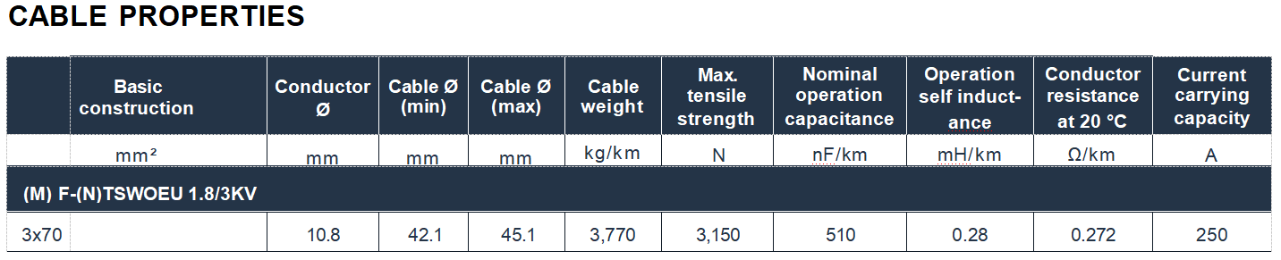
Calculating the minimum bending radius: For a cable with an outer diameter of 45 mm, the minimum fixed installation bending radius is 6 × 45 mm = 270 mm (27 cm). For flexible operation, the minimum radius increases to 10 × 45 mm = 450 mm (45 cm).
Violating these specifications subjects the insulation to excessive stress, potentially causing:
Insulation cracking or separation
Conductor strand breakage
Premature cable failure
Reduced electrical breakdown strength
Increased risk of ground faults
Cable support design must ensure these radius requirements are maintained at all points along the cable route, including both intentional bends and any inadvertent cable deformation that might occur during operation.
Medium Voltage Cable Maintenance Guide
A comprehensive cable maintenance program extends cable service life and prevents unexpected failures. Recommended maintenance activities include:
Visual Inspection: Regularly inspect cables for signs of damage including sheath cuts, abrasions, deformation, discoloration from overheating, or environmental degradation. Pay particular attention to areas near terminations, support points, and locations where the cable crosses equipment or structures.
Electrical Testing: Periodic insulation resistance testing using a megohmmeter verifies insulation integrity. Baseline measurements should be established at installation, with subsequent tests compared to baseline and previous readings. Declining insulation resistance values may indicate moisture ingress, contamination, or insulation degradation.
Thermal Monitoring: Thermal imaging identifies hot spots that may indicate poor connections, overloading, or insulation problems developing. Monitoring should focus on terminations, splices, and areas where the cable may experience mechanical stress.
Support System Maintenance: Inspect and maintain cable support systems to ensure proper cable positioning and prevent stress from sagging or excessive bending. Replace damaged or deteriorated supports promptly.
Documentation: Maintain records of all inspections, tests, and repairs to establish performance trends and guide future maintenance decisions.
Safety Considerations During Installation
Cable installation safety encompasses both electrical and mechanical hazards. Before beginning work, verify that all power sources are disconnected and properly locked out. Medium voltage cables may retain residual charge even after disconnection, requiring proper grounding procedures.
Mechanical safety considerations include proper lifting equipment for heavy cable sections, adequate personnel for manual handling operations, and appropriate personal protective equipment. Installation in active industrial environments requires coordination with facility operations to ensure safe working conditions.
Connection Best Practices for Submersible Pumps
Submersible pump connections require particular attention to water sealing and mechanical strain relief. The cable termination must be completely waterproof, typically accomplished through specialized submersible termination kits that employ heat-shrink tubing, molded rubber, or cast resin techniques.
Mechanical strain relief prevents the cable weight and pump weight from stressing the electrical connections. Cable grips or strain relief devices must be installed to transfer mechanical loads to structural elements rather than electrical connections. In deep installations, consider the cable weight supported by the termination and size strain relief devices accordingly.
The cable should include additional length to accommodate pump removal for maintenance without disconnecting terminations if practical. This service loop must be properly supported to prevent damage from water currents or debris while submerged.
Standards & Certifications
Compliance with international standards ensures cable performance, safety, and compatibility with electrical systems worldwide.
What Does DIN VDE 0250-813 Certification Mean?
DIN VDE 0250-813 provides comprehensive requirements for power cables with rated voltages from 1 kV to 30 kV. This German standard, widely recognized internationally, specifies construction, testing, and performance requirements ensuring cables meet stringent safety and reliability criteria.
Certification to DIN VDE 0250-813 verifies:
Conductor construction meets specified flexibility and conductivity requirements
Insulation materials and thicknesses provide adequate electrical breakdown strength
Manufacturing processes produce consistent, reliable products
Testing protocols verify electrical and mechanical performance
Environmental resistance meets specified criteria
Medium Voltage Cable International Standards
Beyond DIN VDE standards, medium voltage cables are subject to various international standards:
EN 50525-2-21: Specifies electrical parameters including voltage ratings, conductor resistance, and capacitance values. This European standard ensures electrical compatibility across different manufacturers and systems.
DIN VDE 0298-3: Defines mechanical parameters including bending radius requirements, torsional stress limits, and mechanical strength specifications.
IEC 60811-404: Establishes chemical behavior testing methods, ensuring cables withstand exposure to oils, fuels, and other industrial chemicals.
DIN EN 60332-1-2 / IEC 60332-1-2: Fire performance standards verifying flame retardant properties and ensuring cables do not propagate flame under specified test conditions.


Industrial Cable Certification Requirements
Industrial cable certification typically requires compliance with regional safety regulations in addition to product standards. In mining applications, cables may require specific certifications such as MSHA approval for underground coal mining in the United States or similar regional mining authority certifications.
Certification marks provide assurance that cables have undergone rigorous testing and meet all applicable safety and performance standards. Engineers specifying cables should verify that selected products carry certifications appropriate for the intended application and geographic location.
Cable Testing Standards
Cable testing standards define procedures for verifying compliance with performance specifications:
Voltage Testing: High voltage testing at specified test voltages verifies insulation integrity and ensures cables withstand voltage transients and overvoltage conditions.
Partial Discharge Testing: Advanced testing detecting partial discharge activity that could indicate insulation defects or contamination.
Conductor Resistance Measurement: Verifies conductor construction meets specified resistance values, ensuring adequate current carrying capacity.
Mechanical Testing: Evaluates tensile strength, flexibility, and resistance to mechanical damage under conditions simulating installation and operation.
Environmental Testing: Subjects cables to temperature extremes, chemical exposure, UV radiation, and moisture to verify environmental resistance claims.
Electrical Performance
Understanding cable electrical performance characteristics enables proper sizing and application.
5 KV Cable Amperage Capacity
Cable amperage rating depends on multiple factors including conductor size, insulation type, installation method, ambient temperature, and thermal conductivity of the surrounding environment. The F-(N)TSWOEU series offers current ratings from 131 A for 25 mm² conductors to 620 A for 300 mm² conductors under standard rating conditions.
These ratings assume specific installation conditions defined in the standards. Actual current carrying capacity may differ based on:
Ambient Temperature: Higher ambient temperatures reduce current carrying capacity as the cable has less thermal margin before reaching maximum conductor temperature
Grouping: Multiple cables installed in proximity reduce individual cable current capacity due to mutual heating
Burial Depth: Underground installations experience different thermal conditions than aerial installations
Solar Radiation: Cables exposed to direct sunlight experience additional thermal load reducing current capacity
How to Calculate Cable Conductor Resistance
Conductor resistance at 20°C is specified for each conductor size and provides the baseline for calculating voltage drop and power losses. The resistance values for the F-(N)TSWOEU series range from 0.78 Ω/km for 25 mm² conductors to 0.064 Ω/km for 300 mm² conductors.
Temperature correction adjusts conductor resistance for operating temperature:
R_operating = R_20°C × [1 + α(T - 20°C)]
Where α is the temperature coefficient of copper (approximately 0.00393/°C) and T is the operating temperature.
Voltage drop calculation uses conductor resistance to determine voltage loss over cable length:
Voltage Drop = √3 × I × R × L
For three-phase systems, where I is the load current, R is the conductor resistance per kilometer, and L is the cable length in kilometers.
Medium Voltage Cable Electrical Parameters
Insulation Resistance: Minimum insulation resistance values ensure adequate electrical isolation between conductors and between conductors and ground. Values typically exceed several hundred megohms per kilometer for new cables, with lower acceptance criteria for aged cables.
Capacitance: Cable capacitance affects reactive power consumption and voltage regulation. The F-(N)TSWOEU series exhibits capacitance values from approximately 200 to 1030 nF/km depending on voltage rating and conductor size. Higher capacitance requires larger reactive power compensation for long cable runs.
Inductance: Cable inductance influences impedance and voltage drop characteristics. Self-inductance values range from approximately 0.23 to 0.45 mH/km depending on configuration. Lower inductance generally improves power factor and reduces reactive power losses.
Power Transmission Efficiency
Cable power transmission efficiency depends on resistive losses in the conductors. Power loss per phase is calculated as:
P_loss = I² × R × L
Where I is the conductor current, R is the resistance per kilometer, and L is the cable length.
For a three-phase system carrying 250 A through 70 mm² conductors (R = 0.272 Ω/km) over 500 meters:
P_loss = 250² × 0.272 × 0.5 = 8,500 W (8.5 kW) per phase
Total three-phase losses would be 25.5 kW, representing a significant energy cost over the cable's service life. Proper conductor sizing balances initial cable cost against ongoing energy losses to minimize total cost of ownership.
Frequently Asked Questions
Q: What distinguishes semi-flexible cables from fixed installation and fully flexible cables?
A: Semi-flexible cables use Class 5 finely stranded conductors and moderately flexible insulation, permitting installation around bends and occasional repositioning. Fixed cables use less flexible Class 2 conductors suitable only for straight runs or very gentle bends. Fully flexible cables employ Class 6 very finely stranded conductors and specialized rubber compounds for continuous severe bending on cable reels. Semi-flexible cables provide a cost-effective middle ground for applications with moderate flexibility requirements.
Q: Can the F-(N)TSWOEU cable be used in direct burial applications?
A: While the cable's construction provides environmental protection, direct burial typically requires additional mechanical protection or armoring not present in the standard F-(N)TSWOEU design. Consult with cable engineers for direct burial applications to determine if additional protection measures are required based on soil conditions, burial depth, and mechanical loading from surface traffic.
Q: How does temperature affect cable current carrying capacity?
A: Higher ambient temperatures reduce current carrying capacity by decreasing the thermal margin between ambient and maximum conductor temperature. As a general rule, for every 10°C increase in ambient temperature above rating conditions, current capacity decreases by approximately 10-15%. Installation methods that improve heat dissipation (spacing cables, improved ventilation) can partially offset temperature effects.
Q: What causes premature cable failure in industrial applications?
A: Common failure modes include mechanical damage from excessive bending or impact, environmental degradation from chemical exposure or UV radiation, moisture ingress through damaged sheaths, electrical overstress from overloading or voltage surges, and poor installation practices such as exceeding bending radius limits. Proper cable selection, installation, and maintenance substantially reduce failure risk.
Q: How often should medium voltage cables undergo testing?
A: Testing frequency depends on application criticality and operating conditions. As a general guideline, annual visual inspections and insulation resistance testing provide baseline monitoring. More comprehensive testing including partial discharge analysis may be performed every 3-5 years or following significant events such as lightning strikes, short circuits, or mechanical damage incidents. Critical installations may warrant more frequent testing.
Conclusion
The F-(N)TSWOEU I 5 KV medium voltage semi-flexible cable series provides engineered solutions for demanding industrial applications where standard fixed installation cables lack adequate flexibility and fully flexible trailing cables prove unnecessarily expensive. The combination of EPR insulation, chlorinated polyethylene sheathing, and semi-flexible construction delivers reliable performance in conveyor systems, material handling equipment, submersible pump installations, and mining operations.
Proper cable selection requires understanding application requirements including electrical parameters, environmental conditions, and mechanical stresses. Installation must respect minimum bending radius specifications and employ appropriate support systems. Ongoing maintenance through visual inspection, electrical testing, and thermal monitoring maximizes cable service life and prevents unexpected failures.
Compliance with international standards including DIN VDE 0250-813 ensures cables meet rigorous safety and performance requirements. Understanding electrical characteristics enables proper sizing for current carrying capacity, voltage drop, and power transmission efficiency.
The semi-flexible cable category fills an important niche in industrial power distribution, offering flexibility where needed while avoiding the complexity and cost of fully flexible designs. As industrial operations demand increasingly reliable power distribution in challenging environments, properly specified and installed semi-flexible cables provide the performance and durability required for long-term success.
How to Reach Us
Get in Touch
SiteMap
Product Catalogue
Festoon Cable
Shore Power Cable




Scan to add us on WeChat