
Fiber Optic Hybrid Crane Cables in Automated Port Systems: Power, Motion, and Real-Time Data Integration
Find out how fiber optic hybrid crane cables improve automation, data transmission, and motion reliability in STS, RMG, and RTG crane systems for smart ports.
hongjing.Wang@Feichun
7/23/202613 min read
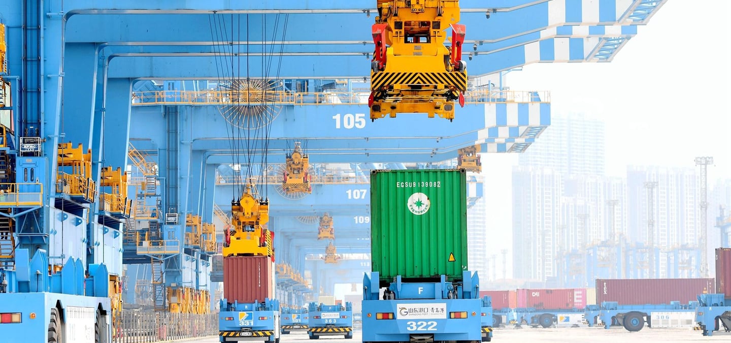
The rapid evolution of maritime trade across Australia has accelerated the transition from conventional, human-operated container handling to fully automated, smart port environments. Major logistics hubs—such as Port Botany in Sydney, Port Phillip Bay in Melbourne, Port of Brisbane, and the heavy bulk and container facilities at Fremantle and Port Adelaide—are undergoing major technological shifts. High-throughput container terminals increasingly deploy Industry 4.0 automation, incorporating automated quay cranes, unmanned rail-mounted gantry systems, and remote operating centers to drive terminal safety, operational efficiency, and round-the-clock ship-to-shore productivity.
At the core of these advanced automated container terminals lies a critical engineering challenge: delivering high-voltage continuous electrical power while simultaneously transferring massive streams of real-time control, video, positioning, and sensor data to and from rapidly moving cranes. Legacy installations historically relied on separate trailing cables for power supply alongside copper control lines or wireless radio links. However, these traditional setups suffer from electromagnetic interference, severe signal latency, physical cable tangling, and high maintenance costs under dynamic reeling conditions.
To address these limitations, modern automated ports rely on fiber optic hybrid crane cables. By integrating high-capacity electrical power conductors, low-voltage control cores, and immune-to-interference optical fiber units into a single dynamic cable architecture, hybrid cables serve as an integrated power and communication platform.
This guide provides a thorough technical breakdown of fiber optic hybrid crane cable design, mechanical motion performance, material selection, electromagnetic resilience, and practical engineering criteria for deployment in demanding Australian port and container handling applications.
1. What Is a Fiber Optic Hybrid Crane Cable?
A fiber optic hybrid crane cable is a specialized, highly flexible dynamic cable engineered specifically to perform two distinct functions simultaneously within a single physical jacket assembly: high-power electrical energy transfer and ultra-fast, high-bandwidth optical data transmission.
Unlike standard power trailing cables or conventional copper control wires, a hybrid cable combines three primary element categories inside its cross-section:
Heavy-Duty Power Conductors: Class 5 or Class 6 fine-stranded tinned copper conductors designed to feed main drive motors, hoist winches, trolley drives, and auxiliary crane transformers at low or medium voltages.
Auxiliary Control Cores: Flexible insulated copper wires utilized for localized safety interlocking, brake control circuits, and secondary control loops.
Integrated Fiber Optic Sub-Units: Single-mode or multi-mode optical fiber bundles encased within protective, crush-resistant central or outer buffer tubes, dedicated exclusively to transmitting digital control signals, high-definition video feeds, and sensor data.
By unifying power, control, and optical communication into a single dynamic umbilical, terminal operators eliminate the need for secondary festoon tracks, complex wireless relays, or separate communication reels. This unified design minimizes total cable mass, simplifies drum reel system design, and provides a continuous, highly reliable link between mobile quay cranes and centralized automated terminal management systems.
2. Cable Structure
Surviving continuous dynamic movement, high-speed payout, and rapid acceleration on automated port cranes requires a meticulously structured internal geometry. Moving from the external boundary to the innermost core, every structural layer performs a critical mechanical, electrical, or optical protection role.
The Outer Sheath Assembly
The outer jacket serves as the first line of defense against severe physical environments. In dynamic crane reeling applications, outer sheathing materials—typically formulated from heavy-duty Polyurethane (TPU) or specialized Chlorinated Polyethylene (CPE) compounds—must provide exceptional resistance against:
Continuous sliding and rolling abrasion on guide sheaves and payout trumpets.
Environmental tearing and physical impacts from loose deck hardware.
Extreme exposure to saltwater spray, ambient humidity, and hydraulic oil leaks.
Degradation from intense solar radiation and high ambient surface temperatures common across Australian port facilities.
Firmly embedded beneath or directly bonded within the outer and inner sheath layers is a high-density braid of synthetic aramid yarn or polyester mesh. This anti-torsional reinforcement mesh locks the internal components together, preventing the outer jacket from twisting or corkscrewing during multi-axis trolley travel or high-speed drum winding.
The Inner Sheath and Core Bedding
Beneath the outer jacket, a flexible inner bedding sheath seals the main cable core. This layer acts as a mechanical buffer, preventing friction and structural abrasion between internal copper conductors, earth cores, and sensitive fiber optic sub-units as the cable flexes over guide sheaves.
Power Conductors and Control Cores
The primary electrical power conductors are positioned symmetrically around the cable’s center. Utilizing high-flexibility, fine-stranded tinned copper wires, these conductors are insulated with high-grade Ethylene Propylene Rubber (EPR) or specialized elastomeric compounds. EPR insulation provides outstanding dielectric strength, high mechanical resilience, and thermal resistance up to continuous operating temperatures of 90°C.
Smaller auxiliary control cores and symmetrically split earth conductors are layered in the outer interstices (the natural geometric gaps between main phase cores) to maintain a perfectly round outer profile, optimize mechanical weight distribution, and prevent inductive coupling imbalances.
Integrated Fiber Optic Sub-Units
The optical fibers are embedded within specialized, protective buffer sub-assemblies positioned either at the geometric center of the cable or nested within protected interstice spaces. Each fiber sub-unit typically consists of multiple color-coded single-mode or multi-mode optical fibers housed within a loose, gel-filled stainless steel tube or a high-strength, flexible synthetic buffer tube.
The jelly filling inside loose buffer tubes acts as a hydraulic shock absorber and moisture barrier, ensuring that external mechanical squeezing, radial crushing, or thermal expansion forces are not transferred directly to the fragile glass fibers.
Central Strength Member
Running along the absolute geometric center of the hybrid cable is a central strength member made from a high-tensile aramid yarn (Kevlar) core or a flexible steel rope encased in a smooth synthetic buffer jacket. The central strength member is engineered to absorb high axial pulling tension during dynamic reeling, ensuring that tensile forces are borne by the strength member rather than transferred to delicate copper strands or optical glass cores.
3. Why Fiber Optics Matter
In modern automated container terminals, optical fiber communication is no longer an optional luxury; it is a fundamental operational necessity. As port cranes transition from manual cabin operators to fully remote operating centers and automated terminal operating systems, the volume and velocity of operational data increase exponentially.
Fiber optic transmission provides distinct technical advantages over traditional copper signal wires:
Immune to Electromagnetic Interference
Port cranes are electrically noisy environments. Large variable frequency drives (VFDs), multi-megawatt hoist motors, heavy contactors, and high-voltage transformer units generate massive electromagnetic interference (EMI) and radio frequency interference (RFI).
Traditional copper control cables running adjacent to high-power motor feeds experience significant inductive voltage spikes, signal noise, and data corruption. Because optical signals consist of light pulses travelling through glass fibers rather than electrical currents moving through copper wire, fiber optic lines are completely immune to electromagnetic fields. Data transfers cleanly alongside high-power 6kV or 10kV motor supply lines without risk of interference.
High Bandwidth and Low Latency
Automated crane operations rely on high-definition camera arrays, 3D LiDAR surface scanning, Optical Character Recognition (OCR) container container tracking, and real-time Programmable Logic Controller (PLC) feedback loops. Transmitting multiple uncompressed video feeds alongside millisecond-accurate positioning control signals requires gigabit-per-second transmission speeds that far exceed the bandwidth capacities of copper signal lines over extended travel distances.
Long-Distance Transmission Without Signal Loss
Automated ship-to-shore cranes and long-run rail-mounted gantry systems routinely travel hundreds of metres along dock faces and storage yards. Copper control signals suffer significant electrical attenuation (signal decay) over long cable runs, requiring signal boosters or repeaters that introduce latency. Fiber optic lines transmit signals over several kilometres with negligible attenuation, ensuring instantaneous feedback between remote operators and mobile crane mechanisms.
4. Automation System Applications
Fiber optic hybrid crane cables serve as the primary power and communication backbone across three main automated container handling equipment categories:
Ship-to-Shore (STS) Cranes
Ship-to-shore quay cranes are massive structures operating at the sea edge, responsible for loading and unloading container vessels. In automated terminals, remote operators seated in comfortably equipped shore-based control rooms guide automated STS cranes using real-time video streams and automated positioning systems.
The hybrid cable on an STS crane powers the main hoist, gantry travel, and trolley drives while simultaneously routing high-definition video feeds, spreader position telemetry, and anti-sway sensor data back to the central control building. High-speed reel dynamics are critical here, as main trolley cables experience acceleration speeds exceeding several metres per second.
Rail-Mounted Gantry (RMG) Cranes
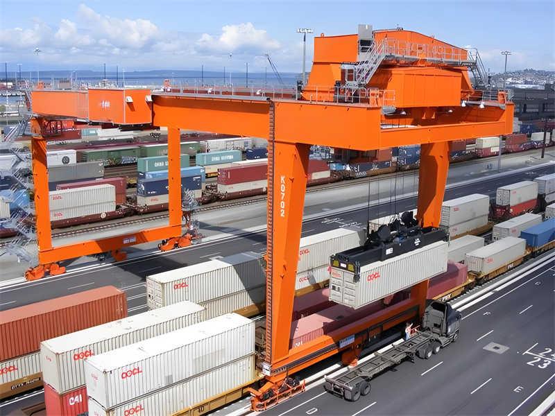
RMGs operate in automated container yards, stacking and sorting containers along extended linear rail corridors. Automated RMGs run continuously on pre-programmed schedules, interacting directly with driverless Automated Guided Vehicles (AGVs) or highway trucks.
Hybrid cables installed on RMGs provide power for gantry movement and container hoisting while continuously exchanging crane positioning data, stack geometry scans, and safety perimeter monitoring signals with terminal operating software.
Rubber-Tyred Gantry (RTG) Cranes
While traditional RTGs rely on diesel generators, modern smart ports are rapidly retrofitting or purchasing electrified RTGs (e-RTGs) powered by dynamic reeling cables or conductor bars. Hybrid reeling cables allow e-RTGs to maintain full zero-emission electric power while integrating directly into automated terminal communication networks via optical fiber sub-units.
5. Smart Port Use Cases
Beyond basic motion control, fiber optic hybrid crane cables unlock advanced Industry 4.0 automation workflows across modern smart ports:
Real-Time Video and Remote Operation
In fully automated container terminals, human operators sit at remote control stations managing multiple cranes simultaneously. Each crane is equipped with multiple high-definition IP cameras focused on the container spreader, twistlocks, truck lane, and surrounding safety clearance zones. The hybrid cable’s optical fiber cores deliver uncompressed, zero-latency video streams to operator consoles, allowing operators to intervene smoothly during critical pick-and-place maneuvers.
Container Identification and Asset Tracking
Automated crane spreaders utilize automated Optical Character Recognition (OCR) camera networks and Radio Frequency Identification (RFID) readers to automatically read container ISO numbers, verify seal integrity, and log container weight data in real time. This information is transmitted over optical fiber lines directly to the Terminal Operating System (TOS), instantly updating global supply chain databases without manual driver logging.
Precision Sensor Networks and Collision Avoidance
Modern automated cranes rely on continuous 3D laser scanners (LiDAR), ultrasonic sensors, and encoder feedback systems to prevent collisions with ship structures, stack piles, or yard vehicles. These precision sensors generate dense streams of positional telemetry that must be processed without delay. Fiber optic hybrid cables ensure that safety-critical sensor data reaches onboard safety PLCs instantly, triggering emergency braking systems if an obstruction enters the working envelope.
6. Why Ordinary Control Cables Are Not Enough
Historically, port cranes relied on heavy multi-core copper control cables (often containing 30 to 50 individual copper cores) to transmit operational signals. In modern automated terminals, relying solely on traditional copper control cables presents severe operational bottlenecks:
Physical Mass and Size Limitations
Transmitting multiple control signals over copper requires adding more individual conductor cores, leading to thick, heavy, and rigid cables. Thick copper cables place massive structural weight loads on machine reels, requiring larger drive motors, larger drum frames, and heavier support structures.
Conversely, a single optical fiber sub-unit containing twelve or twenty-four individual glass fibers has a total diameter of only a few millimetres while offering thousands of times the data capacity of a massive copper control bundle. Replacing copper signal cores with optical fiber dramatically reduces overall cable outer diameter and total mass.
Susceptibility to Signal Decay and Crosstalk
When dozens of copper control wires are bundled tightly inside a single cable adjacent to high-current power conductors, mutual inductive coupling occurs. Electromagnetic noise from power cores induces unwanted signal voltages into adjacent control wires, causing signal noise, corrupted telemetry, and false sensor trips.
Furthermore, as travel distances increase along long quay walls, copper voltage drop degrades control signals, leading to command errors. Fiber optic sub-units are completely immune to crosstalk, electromagnetic noise, and distance-induced voltage decay, guaranteeing clean data transfer over extended runs.
7. Mechanical Performance Requirements
Operating as a flexible power and communication umbilical on dynamic port cranes subjects a hybrid cable to continuous, severe mechanical fatigue. Unlike static building wiring or stationary industrial cables, a hybrid crane cable must be engineered to endure millions of dynamic flex cycles without suffering conductor strand breakage, insulation tearing, or optical fiber fracture.
Key mechanical design parameters include:
High Tensile Strength
During high-speed payout and retrieval, the cable is subjected to severe axial tension caused by the cable’s own suspended weight, acceleration forces, and reel motor torque. High-performance hybrid cables incorporate central aramid strength members and heavy-duty embedded jacket braids that absorb tensile pulling forces up to thousands of Newtons, keeping physical strain off delicate internal copper conductors and glass fibers.
Torsional Resistance
When a crane trolley accelerates or moves through guide sheaves, the cable experiences multi-axis rotational shear and twisting. If a cable lacks torsional resistance, internal core layers untwist or bunch up into localized "bird-cage" deformities, which puncture outer sheathing and snap optical glass fibers. Advanced hybrid crane cables utilize counter-directional conductor lay lengths and anti-torsional textile braids firmly bonded between inner and outer jackets to lock internal components in absolute alignment.
Dynamic Bending Fatigue Resistance
As the cable spools on and off reel drums and travels over guide sheaves, internal phase conductors and optical buffer tubes experience continuous alternating compression and tension. Utilizing fine-stranded Class 5 or Class 6 tinned copper strands alongside loose, gel-filled optical buffer tubes ensures high flexibility and prevents structural metal fatigue over extended operational lifetimes.
8. Reeling and Motion Behavior
The dynamic interaction between a hybrid crane cable and the machine’s motorized reeling system is critical to maintaining continuous optical signal integrity.
Optical Fiber Protection Under Tension and Compression
The primary structural risk in a hybrid cable is ensuring that external mechanical tension applied to the cable during drum winding does not stretch the delicate optical glass fibers. Glass fibers exhibit high tensile strength along their axis but are vulnerable to micro-fractures if stretched or bent beyond tight physical limits.
To protect optical cores, manufacturers utilize excess fiber length (EFL) engineering within loose buffer tubes. Inside the buffer tube, the glass fibers are laid in a subtle helical wave pattern with a slightly longer physical length than the surrounding tube. When the cable experiences heavy pulling tension, the outer buffer tube stretches slightly without putting stress on the relaxed glass fiber inside.
Similarly, when the cable flexes tightly around a reel drum barrel, the gel-filled buffer tube allows internal fibers to float freely toward the neutral axis of bend, preventing severe mechanical compression or micro-bending signal losses.
Managing Micro-Bending and Macro-Bending Losses
Bending an optical fiber too tightly causes light signals travelling down the glass core to leak out through the cladding layer—an effect known as bending loss:
Macro-Bending: Occurs when the entire cable is wrapped around a reel barrel or guide sheave with a radius smaller than the specified minimum bending radius.
Micro-Bending: Occurs when localized mechanical pressure or core crushing pinches the glass fiber internally.
Engineers prevent macro-bending losses by specifying strict minimum bending radius tolerances (typically 10 to 12 times overall cable diameter for dynamic reeling, or 12 to 15 times for high-speed S-bend guide sheaves). Micro-bending losses are prevented through crush-resistant inner sheathing compounds, gel-filled buffer tubes, and precision core geometry.
9. Application Examples
Fiber optic hybrid crane cables are widely deployed across modern, high-tonnage automated container facilities, supporting diverse equipment architectures:
Automated Ship-to-Shore (STS) Trolley and Main Feeder Systems
On high-speed automated STS cranes, hybrid cables operate on main trolley reels and boom trailing systems. These systems transmit medium-voltage power (such as 6.6kV or 11kV) to onboard transformer stations while routing gigabit fiber optic links for operator video feeds, spreader position telemetry, and automated anti-sway sensors.
High-Speed Automated Rail-Mounted Gantry (RMG) Yard Reels
In automated container stacking yards, RMG cranes travel back and forth over extended storage blocks. Mono-spiral or cylindrical motor-driven cable reels spool hybrid cables over travel distances exceeding 300 to 500 metres. The integrated optical fibers connect the RMG’s safety PLCs, laser stack scanners, and container OCR readers directly to central yard management servers.
Australian Heavy Mining Port Bulk Loaders
Beyond container terminals, major Australian bulk export terminals—such as iron ore loading facilities in Port Hedland and coal terminals in Newcastle and Gladstone—utilize hybrid reeling cables on travelling shiploaders, stackers, and reclaimers. These cables deliver power while transferring real-time belt scale weight data, chute position sensors, and environmental dust monitoring signals across expansive jetty structures.
10. Selection Factors
Selecting the correct fiber optic hybrid crane cable requires an integrated evaluation of electrical, optical, mechanical, and environmental parameters.
Engineers, site operators, and procurement specialists should evaluate the following selection criteria:
1. Motion Type and Reeling Configuration
Determine the exact mechanical motion profile: Is the cable deployed on a mono-spiral reel, a multi-layer cylindrical drum, a festoon system, or a dynamic energy chain system? Each reel geometry imposes different bending radiuses, heat dissipation profiles, and torsional loads.
2. Electrical Power and Voltage Requirements
Calculate full load operating current, nominal line voltage, and system short-circuit withstand levels. Size phase conductors appropriately, applying thermal derating factors for high ambient temperatures and multi-layer reel thermal trapping.
3. Optical Fiber Specifications
Specify the required fiber count, glass core diameter, and transmission mode:
Single-Mode Fibers (9/125 $\mu$m): Ideal for long-distance, ultra-high-bandwidth transmission over extended quay walls or port-wide networks.
Multi-Mode Fibers (50/125 $\mu$m or 62.5/125 $\mu$m): Suitable for shorter distances across individual crane structures or localized control loops.
4. Tensile Pulling Force and Bending Radius Limits
Verify that the cable's central strength member and internal reinforcement layer match peak acceleration tension generated by reel drive motors. Ensure guide sheaves and drum barrels meet minimum bending radius guidelines (typically at least 10 to 12 times cable outer diameter).
5. Environmental and Thermal Resilience
Select outer sheathing compounds engineered to survive local environmental conditions. In hot, highly reflective Australian coastal environments, sheaths must exhibit high thermal resistance, extreme UV stability, flame retardancy, and complete resistance to saltwater degradation and industrial grease exposure.
11. Benefits for Automated Systems
Investing in high-performance fiber optic hybrid crane cables delivers substantial operational, safety, and economic advantages for automated port terminals:
Streamlined Cable Architecture: Unifying power, control, and optical communication into a single cable eliminates duplicate reeling systems, festoons, and guidance tracks, reducing dead weight on crane structures.
Maximum Data Throughput with Zero Interference: Optical fiber sub-units provide immune-to-noise, high-bandwidth data transmission, enabling real-time HD video streams, precision positioning, and millisecond-accurate remote operator control.
Reduced Operational Maintenance and Downtime: Robust internal reinforcement, gel-filled buffer tubes, and abrasion-resistant outer sheaths prevent internal conductor strand breakage, optical fiber fracture, and sheath tearing, extending operational service life.
Enhanced Terminal Safety: Replacing manual cable handling and localized operator cabins with remote operation and automated collision avoidance systems significantly reduces personnel exposure to hazardous working zones along active quay walls.
Future-Proof Industry 4.0 Readiness: Hybrid cables provide ample optical fiber capacity to accommodate future sensor additions, automated AI vision upgrades, and expanded terminal management software without requiring costly cable infrastructure replacements.
In demanding mining and port installations where reliability is paramount, specialized industrial cable models manufactured to high international and Australian standards provide the structural resilience required for continuous dynamic reeling. Industrial cable solutions engineered by established manufacturers such as Feichun Cable incorporate tinned copper conductors, high-grade EPR insulation, protective fiber buffer sub-units, and heavy-duty Polyurethane or CPE outer sheaths, ensuring reliable power and signal transmission under dynamic operating conditions.
12. Recommended Conclusion
Fiber optic hybrid crane cables are far more than simple electrical conduits; they serve as the vital power and communication umbilical driving modern automated port systems.
By combining heavy-duty electrical power delivery, flexible auxiliary control cores, and immune-to-interference optical fiber units into a single dynamic assembly, hybrid cables overcome the physical, electrical, and bandwidth limitations of legacy wiring systems. They allow automated container terminal cranes, automated RMGs, and smart port machinery to operate with absolute precision, high data throughput, and uninterrupted electrical reliability.
Achieving long-term operational success requires matching cable cross-section geometry, tensile strength ratings, fiber specifications, and outer sheath materials with actual mechanical reeling dynamics and site environmental conditions. When properly specified, engineered, and installed, fiber optic hybrid crane cables provide a durable, efficient, and future-proof platform for high-throughput container terminals and next-generation smart port automation.
How to Reach Us
Get in Touch
SiteMap
Product Catalogue
Festoon Cable
Shore Power Cable




Scan to add us on WeChat