
High-Performance 6.35/11 kV Copper Cables AS/NZS 1972 Standard: Armoured, Screened & Rated Solutions for Industrial Power Distribution
Discover AS/NZS 1972-compliant 6.35/11 kV copper cables engineered for extreme environments. Explore screened, armored three-core power cables, technical specifications, installation guidelines, and long-term reliability tips.
AS/NZS MINING CABLE
hongjing.Wang@Feichun
8/19/202512 min read
Introduction
1.1 Overview of 6.35/11 kV Copper Cables
High-voltage power distribution systems in Australia and New Zealand rely heavily on robust, reliable medium-voltage cables capable of withstanding extreme environmental conditions whilst maintaining optimal electrical performance. The 6.35/11 kV copper cables represent a critical component in industrial power networks, particularly in mining operations, heavy manufacturing, and utility infrastructure where uninterrupted power supply is paramount.
These three-core copper wire screened armoured cables are specifically engineered to deliver consistent electrical performance across nominal conductor areas ranging from 25 mm² to 240 mm². The voltage rating of 6.35/11 kV indicates the cable's capability to operate at 6.35 kV phase-to-earth voltage with a maximum system voltage of 11 kV phase-to-phase, making them suitable for primary supply applications in demanding industrial environments.
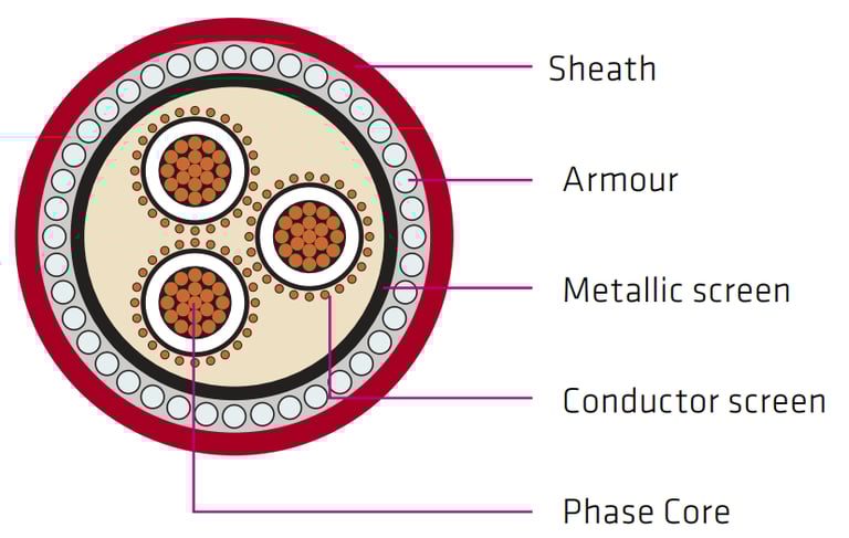
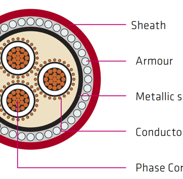
The construction methodology employs cross-linked polyethylene (XLPE) insulation, semiconductor screening layers, copper wire screening, galvanised steel wire armour, and PVC outer sheathing. This multi-layered approach ensures exceptional mechanical protection, electrical insulation integrity, and environmental resistance throughout the cable's operational lifespan.
1.2 Importance of AS/NZS 1972 Compliance
Compliance with AS/NZS 1972 standard represents more than mere regulatory adherence—it signifies a commitment to safety, reliability, and performance excellence in medium-voltage cable applications. This Australian and New Zealand joint standard establishes comprehensive requirements for power cables with voltages exceeding 1 kV, encompassing design specifications, materials selection, manufacturing processes, and performance testing protocols.
The AS/NZS 1972 standard ensures that 6.35/11 kV copper cables meet stringent electrical, mechanical, and environmental performance criteria essential for safe operation in industrial applications. These requirements include specific parameters for conductor resistance, insulation thickness, screen conductivity, armour tensile strength, and flame retardancy characteristics.
1.3 Target Applications and Industry Sectors
Primary applications for these high-performance cables include mining operations, where reliable power distribution to underground equipment and surface processing facilities is critical. Industrial manufacturing plants, particularly those involving heavy machinery and continuous process operations, benefit from the robust construction and reliable performance characteristics of AS/NZS 1972 compliant 6.35/11 kV copper armoured cables.
Utility companies utilise these cables for primary distribution networks, particularly in urban environments where underground installation provides aesthetic and practical advantages over overhead lines. The cables' suitability for direct burial, duct installation, and free-air mounting provides flexibility in system design and installation methodology.
Standards & Approvals
2.1 AS/NZS 1972: Scope and Requirements
The AS/NZS 1972 standard encompasses comprehensive requirements for power cables operating at voltages from 1.9/3.3 kV to 19/33 kV, with the 6.35/11 kV rating falling within the standard's core application range. This standard specifies detailed requirements for conductor materials, insulation systems, screening arrangements, armour configurations, and outer sheathing materials.
Key aspects covered include dimensional tolerances, electrical performance parameters, mechanical strength requirements, and environmental resistance characteristics. The standard mandates specific testing procedures including routine electrical tests, sample tests, and type approval tests to ensure consistent quality and performance across all manufactured cables.
2.2 Key Performance Criteria (Screening, Armour, Temperature)
The screening system in AS/NZS 1972 compliant cables comprises extruded semiconductor screens applied over each conductor and a metallic screen consisting of plain annealed copper wire. The combined screen area must provide not less than 50% conductance of one associated power conductor, ensuring effective fault current paths and electromagnetic compatibility.
Galvanised steel wire armour provides mechanical protection against impact damage, crush forces, and rodent attack whilst offering additional fault current capacity. The armour wire diameter varies from 2.5 mm for smaller conductor sizes to 3.15 mm for larger configurations, optimising protection levels against mechanical stress.
Temperature performance criteria establish maximum operating temperatures of +90°C and minimum operating temperatures of -25°C, ensuring reliable operation across Australia's diverse climatic conditions from tropical Queensland to alpine regions in Tasmania and New Zealand's South Island.
2.3 Certification Bodies and Regulatory Compliance
Certification of AS/NZS 1972 compliant cables involves rigorous testing by accredited laboratories, with ongoing quality assurance programs ensuring consistent manufacturing standards. Regular audits and performance monitoring maintain compliance throughout the production lifecycle, providing end-users with confidence in long-term reliability and safety performance.
Construction & Design Features
3.1 Conductor Material: Three-Core High-Purity Copper
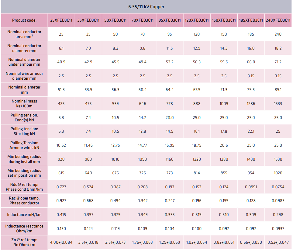
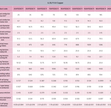
The conductor system employs plain circular compacted copper construction, optimising current-carrying capacity whilst minimising overall cable dimensions. Conductor areas range from 25 mm² to 240 mm², with corresponding diameters from 6.1 mm to 18.2 mm, providing flexibility in system design and load requirements.
Compacted copper construction reduces conductor resistance compared to standard stranded configurations whilst maintaining mechanical flexibility essential for installation in varying terrain conditions. The high-purity copper specification ensures minimal impurities that could compromise electrical performance or accelerate degradation over time.
3.2 Insulation and Screen (Semi-Conductive Layer)
Cross-linked polyethylene (XLPE) insulation provides excellent dielectric properties, thermal stability, and resistance to electrical treeing and water absorption. The insulation system incorporates semiconductor screens applied directly over the conductor and under the metallic screen, eliminating air voids and ensuring uniform electric field distribution.
These semiconductor layers are extruded simultaneously with the XLPE insulation, creating intimate bonding that prevents delamination during thermal cycling and mechanical stress. The screening arrangement effectively contains the electric field within the insulation system whilst providing a defined equipotential surface for reliable electrical performance.
3.3 Armoring Details: Wire Armour Diameter & Mechanical Protection
Galvanised steel wire armour construction varies according to cable size, with 2.5 mm diameter wires used for conductor sizes up to 150 mm², and 3.15 mm diameter wires for 185 mm² and 240 mm² configurations. This sizing optimisation ensures adequate mechanical protection whilst minimising cable weight and installation complexity.
The armour provides exceptional resistance to mechanical damage from excavation activities, ground settlement, and impact forces. Pulling tensions for armour wires range from 10.52 kN for 25 mm² cables to 25.0 kN for larger sizes, ensuring integrity during installation operations.
3.4 Outer Sheath Materials and Environmental Resistance
The red 5V-90 polyvinyl chloride (PVC) outer sheath provides comprehensive environmental protection against moisture ingress, chemical exposure, solar radiation, and weathering effects. This formulation offers very good resistance to frequent chemical exposure and excellent protection against solar radiation and weather exposure.
The flame retardant characteristics of the outer sheath comply with relevant safety standards, preventing fire propagation whilst maintaining structural integrity during emergency conditions. Water splash resistance ensures reliable operation in wet environments typical of industrial applications.


Technical Specifications
4.1 Nominal Conductor Area and Diameter (25–240 mm²)
The comprehensive range of conductor sizes accommodates diverse load requirements, from auxiliary services using 25 mm² conductors to primary feeders requiring 240 mm² capacity. Each size maintains precise dimensional tolerances ensuring consistent electrical and mechanical performance across the entire range.
Three core screened armored copper power cable specifications include nominal conductor diameters ranging from 6.1 mm for 25 mm² conductors to 18.2 mm for 240 mm² configurations, with corresponding variations in overall cable diameter from 51.3 mm to 85.1 mm including outer sheath.
4.2 Electrical Properties: Rdc, Rac, Zo, Capacitance, Inductance
DC resistance values at reference temperature range from 0.727 Ω/km for 25 mm² conductors to 0.0754 Ω/km for 240 mm² configurations, with AC resistance at operating temperature accounting for skin effect and proximity losses. These precise specifications enable accurate voltage drop calculations and system design optimisation.
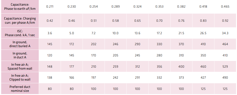
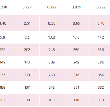
Zero sequence impedance values incorporate both resistance and reactance components, essential for fault analysis and protection system coordination. Capacitance values from 0.211 µF/km to 0.465 µF/km phase-to-earth influence charging currents and power factor considerations in system design.
4.3 Mechanical Ratings: Pulling Tensions, Bending Radii
Pulling tension specifications vary according to installation method, with conductor pulling tensions ranging from 5.3 kN for 25 mm² cables to 25.0 kN maximum for larger sizes. Stocking tensions and armour wire tensions are specified separately, ensuring appropriate installation techniques for each cable component.
Minimum bending radius requirements distinguish between installation conditions (dynamic bending) and final positioning (static bending), with installation radii ranging from 920 mm to 1530 mm and positioned radii from 615 mm to 1020 mm for the complete size range.
4.4 Thermal Ratings: Minimum Operating Temperature (−25 °C) and Current Carrying Capacity
Current carrying capacities vary significantly with installation method, with direct burial installations providing the highest ratings from 145 A to 464 A across the conductor size range. In-duct installations show reduced capacity from 120 A to 410 A, whilst free-air installations achieve intermediate performance levels.
High-temperature rated 6.35/11 kV copper cable installation guide specifications acknowledge the thermal limitations imposed by XLPE insulation, with conductor temperatures limited to 90°C continuous operation and short-circuit temperatures not exceeding 250°C.


Installation Guidelines
5.1 Trench & Duct Requirements (Preferred Duct Sizes)
Preferred duct nominal sizes range from 80 mm for smaller cable configurations to 125 mm for the largest sizes, ensuring adequate clearance for cable installation whilst minimising excavation requirements. Duct selection must consider cable pulling tensions, bending radius limitations, and thermal dissipation requirements.
Trench installations require careful consideration of backfill materials, compaction procedures, and thermal environment to ensure optimal cable performance. Direct burial applications benefit from selected backfill materials providing good thermal conductivity whilst preventing mechanical damage from stones or debris.
5.2 Bending Radius Best Practices During Pull-In and In-Position
Dynamic bending radius requirements during cable pulling operations must account for the higher mechanical stresses imposed during installation. The specified installation radii provide adequate safety margins whilst maintaining cable integrity throughout the pulling process.
Static bending radius specifications for cables in their final installed position reflect the reduced stress levels in permanent installations. Proper support arrangements and cable routing ensure compliance with minimum bending radius requirements whilst facilitating future maintenance access.
5.3 Direct Burial vs. In-Duct vs. Free-Air Clipped Installations
Direct burial installations offer the highest current carrying capacity due to superior heat dissipation to the surrounding soil, making this method preferred for high-load applications. However, accessibility for future maintenance and modifications may be limited compared to alternative installation methods.
In-duct installations provide excellent mechanical protection and facilitate cable replacement when required, though thermal performance is reduced compared to direct burial. Free-air installations offer maximum accessibility for inspection and maintenance whilst providing intermediate thermal performance.
5.4 Stocking, Pulling, and Termination Techniques
Proper stocking arrangements utilise cable grips specifically designed for armoured cables, distributing pulling forces appropriately between conductors and armour wires. Pulling tensions must not exceed specified limits for any cable component to prevent damage during installation.
Termination techniques for screened armoured cables require specialised procedures ensuring continuity of screening systems and proper earth connections. Armour termination must provide mechanical strain relief whilst maintaining electrical continuity for fault protection purposes.
Performance & Reliability
6.1 Short-Circuit Withstand Capacity (1 sec ISC Ratings)
Short-circuit withstand ratings range from 3.6 kA for 25 mm² conductors to 34.3 kA for 240 mm² configurations, based on one-second fault duration. These ratings ensure cable integrity during protection system operation, preventing thermal damage that could compromise long-term reliability.
The thermal capacity calculations account for conductor material properties, insulation thermal limits, and heat dissipation characteristics during fault conditions. Proper protection system coordination ensures fault clearing within the cable's thermal withstand capability.
6.2 Long-Term Aging and Environmental Degradation
XLPE insulation systems demonstrate excellent aging characteristics when properly installed and operated within specified temperature limits. The material's resistance to oxidation, thermal degradation, and electrical treeing contributes to service lives exceeding 30 years in appropriate applications.
Environmental factors including moisture, chemicals, and mechanical stress can influence aging rates, emphasising the importance of proper installation techniques and ongoing maintenance programs. Regular condition monitoring identifies potential issues before they compromise system reliability.
6.3 Maintenance & Inspection Protocols
Routine maintenance programs should include visual inspection of exposed cable sections, monitoring of cable temperatures during peak loading, and periodic electrical testing to assess insulation condition. Thermographic surveys identify hot spots indicating potential connection problems or overloading.
Advanced diagnostic techniques including partial discharge monitoring and tan delta testing provide early warning of developing insulation problems. These techniques enable predictive maintenance strategies that maximise cable service life whilst minimising unplanned outages.


Comparative Analysis
7.1 6.35/11 kV Copper vs. Aluminum Cables
Copper conductor cables offer superior electrical conductivity compared to aluminium alternatives, resulting in lower resistance losses and reduced voltage drop for equivalent conductor sizes. The mechanical properties of copper provide better resistance to work-hardening and connection problems that can affect aluminium cables.
However, aluminium cables offer significant weight and cost advantages, particularly for larger conductor sizes and long cable runs. The selection between copper and aluminium requires careful evaluation of electrical performance requirements, installation constraints, and lifecycle costs.
7.2 Screened Armoured vs. Unscreened Unarmoured Cables
Screened armoured construction provides comprehensive protection against electrical and mechanical hazards, making these cables suitable for harsh industrial environments. The screening system ensures electromagnetic compatibility whilst the armour provides mechanical protection against damage during and after installation.
Unscreened unarmoured alternatives may be suitable for protected installations where cost optimisation is prioritised over maximum protection levels. However, the enhanced reliability and safety characteristics of screened armoured cables justify their use in critical applications.
7.3 Cost-Benefit and Lifecycle Considerations
Initial costs for high-specification cables are offset by enhanced reliability, reduced maintenance requirements, and extended service life. The total cost of ownership analysis must consider installation costs, operational losses, maintenance expenses, and replacement costs over the cable's service life.
Lifecycle cost optimisation often favours higher-quality cables in critical applications where outage costs exceed the premium for enhanced specifications. Proper cable selection based on application requirements and lifecycle considerations ensures optimal economic and technical performance.
Long-Tail Keyword Integration
8.1 AS/NZS 1972 Compliant 6.35/11 kV Copper Armoured Cables
These specialised cables represent the pinnacle of medium-voltage cable technology, combining compliance with Australian and New Zealand standards with robust construction methodology. The comprehensive specification ensures reliable performance across diverse industrial applications whilst maintaining safety and environmental protection standards.
8.2 Three Core Screened Armoured Copper Power Cable Specifications
The detailed specifications encompass all aspects of cable performance, from electrical characteristics through mechanical properties to environmental resistance capabilities. This comprehensive approach ensures suitability for demanding applications whilst providing designers with accurate data for system optimisation.
8.3 High-Temperature Rated 6.35/11 kV Copper Cable Installation Guide
Installation guidelines recognise the critical importance of proper installation techniques in achieving optimal cable performance and service life. Temperature considerations during installation and operation ensure that cables perform within their design parameters throughout their operational lifespan.
Application Scenarios and Potential Issues
Mining Operations
In underground mining environments, these cables must withstand extreme conditions including high temperatures, moisture, mechanical vibration, and potential exposure to corrosive substances. The robust construction with galvanised steel wire armour and chemical-resistant outer sheath ensures reliable operation in these demanding conditions.
Common issues in mining applications include mechanical damage from mobile equipment, thermal stress from high ambient temperatures, and moisture ingress in humid underground conditions. Regular inspection protocols and protective measures mitigate these risks whilst maintaining operational reliability.
Industrial Manufacturing
Heavy manufacturing facilities require reliable power distribution to maintain continuous production processes. The high current carrying capacity and short-circuit withstand capability of these cables ensure adequate supply to large motors, furnaces, and processing equipment.
Potential issues include overloading during peak production periods, exposure to industrial chemicals, and mechanical damage from maintenance activities. Proper cable sizing, protective measures, and maintenance procedures address these concerns whilst ensuring operational continuity.


Frequently Asked Questions
Q: What is the maximum continuous operating temperature for 6.35/11 kV copper cables?
A: The maximum continuous operating temperature is +90°C for the conductor, which corresponds to the thermal limit of the XLPE insulation system. Exceeding this temperature can accelerate aging and reduce cable service life.
Q: Can these cables be installed in areas with high chemical exposure?
A: Yes, the PVC outer sheath provides very good resistance to frequent chemical exposure. However, specific chemical compatibility should be verified for particular applications involving aggressive substances.
Q: What is the minimum bending radius during installation?
A: Minimum bending radius during installation varies from 920 mm for 25 mm² cables to 1530 mm for 240 mm² cables. These values ensure cable integrity during pulling operations.
Q: How do I determine the appropriate duct size for installation?
A: Preferred duct sizes range from 80 mm for smaller cables to 125 mm for the largest configurations. The duct must accommodate the cable's outer diameter with adequate clearance for installation and thermal performance.
Q: What maintenance is required for screened armoured cables?
A: Regular visual inspections, thermal monitoring, and periodic electrical testing are recommended. Advanced diagnostic techniques like partial discharge monitoring can provide early warning of developing issues.
Conclusions & Recommendations
9.1 Selecting the Right Cable for Your Project
Proper cable selection requires comprehensive evaluation of electrical requirements, environmental conditions, installation constraints, and lifecycle considerations. The range of conductor sizes from 25 mm² to 240 mm² accommodates diverse load requirements whilst the robust construction ensures reliable operation in demanding applications.
Consider current carrying capacity requirements, voltage drop limitations, short-circuit withstand capability, and future expansion possibilities when selecting conductor size. Environmental factors including temperature extremes, chemical exposure, and mechanical hazards influence construction requirements and installation methods.
9.2 Ensuring Compliance and Safety
AS/NZS 1972 compliance ensures that cables meet comprehensive safety and performance requirements established through extensive testing and industry experience. Regular inspection and maintenance programs maintain these performance standards throughout the cable's operational life.
Proper installation techniques, adherence to bending radius limitations, and appropriate termination procedures are essential for maintaining compliance and ensuring safe operation. Professional installation and commissioning services provide confidence in long-term reliability and regulatory compliance.
9.3 Future Trends in Medium-Voltage Cable Technology
Advances in materials science continue to improve cable performance whilst environmental considerations drive development of more sustainable manufacturing and disposal processes. Smart cable technologies incorporating sensors and monitoring systems enable predictive maintenance strategies that optimise reliability and lifecycle costs.
The evolution towards renewable energy systems and smart grid technologies requires cables capable of handling bidirectional power flows and dynamic loading conditions. AS/NZS 1972 compliant 6.35/11 kV copper cables provide the foundation for these emerging applications whilst maintaining the reliability and safety standards essential for critical infrastructure applications.
These high-performance cables represent a proven solution for demanding industrial applications where reliability, safety, and long-term performance are paramount. Proper selection, installation, and maintenance ensure optimal service life and operational effectiveness across diverse application scenarios.
How to Reach Us
Get in Touch
SiteMap
Product Catalogue
Festoon Cable
Shore Power Cable


Scan to add us on WeChat