
How Fleet Angle Impacts Crane Cable Service Life: Failure Modes, Field Lessons and Engineering Fixes
Fleet angle is one of the most underrated causes of premature crane cable failure on RTG, STS and RMG systems. Here's how it damages reeling and drum cables, the field failure modes to watch for, and the practical fixes that extend service life.
hongjing.Wang@Feichun
6/3/202612 min read
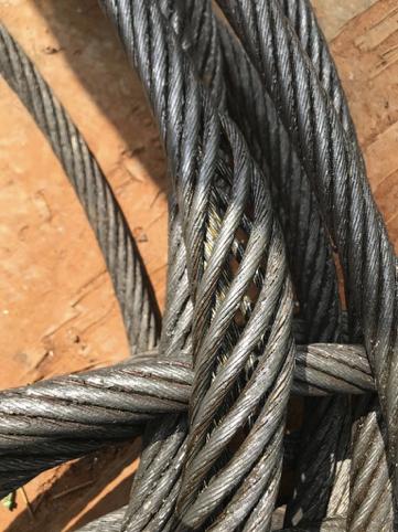
When a reeling cable lets go on a busy container terminal, the cable itself usually takes the blame. It's the part that visibly failed, after all. But anyone who has spent time around port cranes and material handling gear knows the truth is rarely that simple. More often than not, the cable was the victim, not the culprit — and one of the quietest, most common offenders is something you can't see in a photograph and rarely think about until it bites you: fleet angle.
Get the fleet angle wrong, even by a degree or two, and you can knock years off the life of an otherwise excellent cable. Get it right, and the same cable will quietly do its job through millions of duty cycles. This guide walks through what fleet angle actually is, why it matters so much to cable longevity, the real failure modes it produces in the field, and what engineers and maintenance crews can do to keep cables alive longer. If you run, maintain or specify cranes, the payoff is fewer unplanned shutdowns and a much healthier maintenance budget.
Why Crane Cable Failures Keep Catching Operators Out
Modern container terminals run at a punishing tempo. Ship-to-shore cranes are expected to cycle continuously, rubber-tyred gantries shuttle back and forth with constant acceleration and braking, and automated rail-mounted gantries demand precise, repeatable cable tracking around the clock. The cable feeding power to all that motion is doing an extraordinary amount of mechanical work, and when it fails the whole machine usually stops with it.
That downtime is where the real cost lives. A reeling cable might be a modest line item on a purchase order, but the lost moves, the idle gang, the emergency call-out and the knock-on scheduling chaos are anything but modest. So it pays to understand why these cables fail prematurely in the first place.
The usual suspects are familiar enough — overloading, poor lubrication of guide components, tight bending radii, wear in worn sheaves and rollers, and simple neglect. Industry inspectors who pull thousands of damaged ropes and cables a year keep coming back to the same short list, and improper fleet angle into the sheaves and onto the drum sits right near the top of it.
The parameter everyone overlooks
Fleet angle is one of the most important design parameters in any cable reeling system, yet it's also one of the most commonly botched during installation and one of the least understood on the maintenance floor. Part of the problem is that the consequences are delayed. A bad fleet angle doesn't blow the cable up on day one. It works away in the background — a bit of extra abrasion here, a touch of torsional stress there — and by the time the symptoms are obvious, months of damage are already baked in.
A seemingly trivial installation error, a deflector sheave mounted slightly too close or a touch off-centre, can dramatically shorten cable service life. The cable that should have lasted five years gives up in two, and the post-mortem blames the cable rather than the geometry that destroyed it.
What Fleet Angle Actually Is
Picture a cable running off a fixed lead sheave (the deflector pulley) and winding onto a rotating drum. As the cable spools across the width of that drum, it has to travel sideways from one flange to the other. Fleet angle is the angle between the cable and a line drawn perpendicular to the drum axis — in plain terms, how far the cable has to lean sideways to reach the part of the drum it's winding onto at that moment.
Crucially, the angle isn't constant. When the cable is winding onto the centre of the drum, directly in line with the sheave, the fleet angle is close to zero. When it's winding onto the outer edges of the drum, furthest from the sheave's line of travel, the angle is at its largest. So during normal winding and unwinding the fleet angle is continuously changing, swinging from one extreme to the other and back with every pass across the drum.
That sideways lean determines how the cable tracks. A well-controlled fleet angle keeps the cable laying down neatly, spooling tightly and evenly, with mechanical forces spread sensibly through the structure. A poorly controlled one forces the cable to drag sideways, climb over itself, grind against flanges and twist as it lands. The cable's path alignment, its spooling behaviour and the distribution of forces inside it are all governed by this single geometric relationship.
How big should the angle be?
There's broad agreement across the industry on sensible limits, and it depends on the drum.
For a smooth (ungrooved) drum, the cable relies on tension and tracking to find its place, so the angle has to stay tight. The common recommendation is roughly 0.5° to 1.5°, with 1.5° widely treated as the maximum safe operating limit. Pushed beyond that, the cable struggles to lay down cleanly and starts piling, gapping or climbing.
For a grooved drum, the helical groove physically guides each wrap into place, which buys a bit more tolerance. The typical operating range runs from about 0.5° up to 2°. The groove improves winding accuracy and cable guidance, which is exactly why grooved drums are favoured on demanding, high-cycle reeling duties.
These figures line up with the rule-of-thumb ratios riggers are taught: a smooth drum wants the deflector sheave far enough away to keep the angle inside roughly a 40:1 ratio of sheave distance to half the drum width, while a grooved drum can live with something nearer 30:1.
Why too small is also a problem
It's tempting to assume that if a small fleet angle is good, then zero must be perfect. It isn't. If the angle is too small, the cable has no encouragement to move sideways across the drum at all. Instead of distributing itself across the full width, it tends to pile up in one spot, building a heap that eventually collapses sideways and creates uneven, lumpy winding. Poor lateral movement and cable piling produce their own crop of problems — crush damage, snatch loads and erratic tracking. The goal isn't the smallest possible angle; it's the right angle.
Designing it in from the start
The practical levers are simple to state and worth getting right at the design stage. The lead sheave needs to sit at the correct distance from the drum so that the maximum angle, when the cable is at the far flange, stays within the limits above. Drum width matters too — a very wide drum at a short sheave distance is a recipe for an excessive angle at the edges. For crane manufacturers and maintenance teams, the best-practice habit is to verify the geometry on paper before anything is bolted down, then confirm it on the machine and recheck it after any modification to the reel, the deflector or the cable route.
Why Fleet Angle Directly Shortens Cable Life
So why does a few degrees of misalignment cause so much grief? It comes down to the kinds of stress an off-angle introduces, all of which a cable hates.
Uneven sidewall loading. When the cable approaches the drum at too steep an angle, it presses hard against one side of the groove or against the adjacent wrap and the drum flange. That lateral force concentrates stress along one edge of the cable rather than spreading it around. Concentrated stress zones are fatigue zones, and the result over time is accelerated mechanical fatigue in exactly the spots that bear the load.
Excessive torsional stress. Pulling a cable sideways doesn't just bend it — it twists it. Every side-pull as the cable lands tends to rotate it slightly, and reeling cables are, frankly, not designed to handle torsion well. They tolerate some — quality medium-duty reeling and drum cables are typically rated for torsional stresses on the order of ±50 degrees per metre, and lighter festoon and basket types far less — but a misaligned guidance system feeds in twist that was never part of the design budget. That torsion accumulates as internal stress, and the cable structure degrades progressively from the inside.
Friction and abrasion. A cable that's dragging sideways rubs against things it shouldn't: the adjacent wrap (cable-to-cable), the drum surface or groove (cable-to-drum), and the flange (cable-to-flange). Each contact scrubs away at the outer sheath. Abrasion damage of this kind is one of the classic fingerprints of a bad fleet angle, and it's exactly the wear inspectors point to when they find a sheath worn thin at predictable points.
Lost flexibility. Cyclic deformation under side load fatigues the sheath and insulation compounds. Over thousands of cycles the materials stiffen and lose their dynamic give, so the cable that once flexed happily starts to resist bending, which only piles on more stress. Declining flexibility is both a symptom and an accelerant.
The bottom line on cost. All of this rolls up into total cost of ownership. A cable fighting a bad fleet angle needs inspecting more often, fails sooner and tends to fail without warning — more maintenance hours, more unplanned downtime and earlier replacement than its design life should ever have required.
Six Failure Modes You'll Actually See in the Field
The theory is one thing; what shows up on the workshop bench is another. These are the recurring patterns that field experience associates with fleet-angle problems. The thread running through all of them is the same: many of these failures originate in installation and geometry, not in the cable's quality.
1. The cable jumps out of the sheave groove
You'll see a cable repeatedly leaving its pulley groove, tracking unevenly and needing replacement far too often. The root causes cluster together — an excessive fleet angle that pushes the cable to climb the side of the groove, uneven tension that lets it wander, worn guide components that no longer constrain it, and misaligned sheaves that send it off-line. The consequences are nasty: severe jacket damage as the cable scrapes over the groove edge or sheave cheek, permanent deformation, and a real hit to operational safety when the cable can leave its intended path entirely.
2. Severe sheath abrasion at drum crossover points
On a multi-layer drum, each new layer crosses over the one below it at the flange. Where those layers cross is a natural pressure point, and a poor fleet angle makes it far worse. The wear concentrates right at those layer transition zones. The symptoms are unmistakable: a flattened outer jacket, scraped sheath surfaces and, in advanced cases, exposed reinforcement layers beneath. The drivers are poor spooling geometry, excessive fleet angle and high crossover pressure during multi-layer winding. Once the sheath is breached you get water ingress and loss of mechanical protection, and the cable is on borrowed time.
3. Hidden conductor breakage from repeated flexing
This is the sneaky one. The outer jacket looks perfectly intact, yet the crane throws intermittent electrical faults that come and go maddeningly. Inside, the copper conductors have fatigued and started breaking from repeated bending cycles, excessive mechanical stress and improper cable guidance. It shows up most in high-cycle bending zones — reeling systems and spreader cables especially. Because nothing looks wrong from outside, troubleshooting is slow and frustrating, the crane suffers unexpected shutdowns, and maintenance costs climb while crews chase a fault they can't see.
4. Core separation and tensile failure
Here the internal cores begin pulling away from the outer sheath, and the cable progressively loses its structural integrity. You'll spot jacket separation, stretched conductors and core slippage. The causes are sustained tensile loading, side-pulling forces from a bad fleet angle, and generally improper reeling conditions that load the cable in ways it wasn't built for. The end state is mechanical failure, electrical instability and a complete cable replacement. This is why quality reeling cables are built with reinforced support members and an anti-torsion braid bonded between the sheaths — to share the tensile and torsional load the side-pull keeps trying to dump onto the conductors.
5. Deformation and twisting under side pressure
When a cable is repeatedly compressed sideways, it flattens and distorts, and over time it can take on a progressive twist that it never sheds. The causes are excessive sidewall compression, improper fleet angle and poor drum geometry working together. The result is a cable that's lost its flexibility, suffered internal structural damage and aged well before its time.
6. Bird-caging from excessive torsional loads
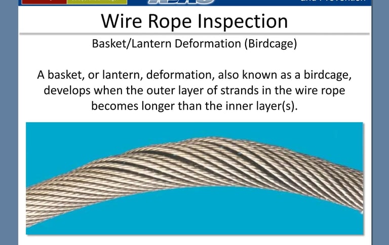
Bird-caging is the dramatic one. Under torsional imbalance, the internal strands displace outward and the cable structure swells into a shape like a wicker birdcage — hence the name. Fleet angle contributes directly: cable rotation during reeling, the steady accumulation of torsional loads and the internal stress concentration that follows all feed it. The damage is permanent. There's no recovering a bird-caged section; service life drops sharply and the risk of a sudden, catastrophic failure rises. It's the clearest possible signal that torsion has overwhelmed the cable.
Where Fleet Angle Bites Hardest in a Port
Different machines stress cables in different ways, and fleet angle plays a role across the board.
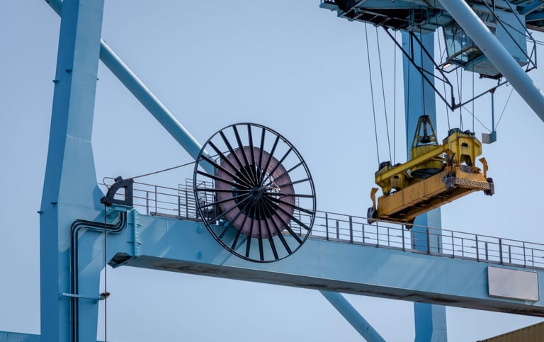
Ship-to-shore (STS) cranes combine long travel distances, high-speed reeling and continuous operation cycles. The sheer reeling speed and the length of cable being managed leave little margin for a sloppy angle.
Rubber-tyred gantry (RTG) cranes live on frequent acceleration and deceleration, with the cable in constant dynamic movement. Every snatch and surge that a poor angle adds to is amplified by the duty cycle.
Rail-mounted gantry (RMG) cranes, increasingly automated, demand precise and repeatable cable tracking. Automation has little tolerance for a cable that wanders, so tracking accuracy — and therefore fleet angle — is paramount.
Spreader and auxiliary cable systems face repetitive bending and high torsional loads in tight spaces, exactly the conditions that turn a marginal fleet angle into hidden conductor breakage or twisting.
Bulk handling equipment — stacker reclaimers, ship unloaders and bucket-wheel excavators — runs reeling and festoon cables under heavy, dirty, high-cycle conditions where geometry errors compound quickly.
How to Minimise Fleet-Angle-Related Failures
The good news is that almost all of this is preventable. The fixes aren't exotic; they're about discipline in design, installation and inspection.
Get the lead sheave position right. This is the single highest-leverage move. Set the correct sheave-to-drum distance for your drum width so the maximum angle stays inside the limits, and maintain proper cable entry geometry so the cable arrives at the drum the way the designer intended.
Improve the drum design where you can. Grooved drums earn their keep on demanding reeling duties: they give better cable guidance, lay each wrap where it belongs and reduce the crossover stress that chews up sheaths on multi-layer winding. Where a smooth drum is unavoidable, keeping the angle tight matters even more.
Inspect alignment regularly. Build a habit of checking guide-roller wear, confirming sheave alignment and looking for signs of flange contact. Worn or seized rollers and a sheave that's drifted out of line will manufacture a bad fleet angle no matter how perfect the original install was.
Watch for the early warning signs. Uneven jacket wear, any sign of twisting, the first hint of bird-caging and abnormal cable tracking are all telling you the geometry is off. Catching them early is the difference between a cleaning-up adjustment and a cable replacement.
Run a real preventive maintenance programme. Set sensible inspection intervals, define clear wear-measurement procedures and agree replacement criteria in advance so decisions are made on evidence rather than in a panic when something's already failed.
Choosing a Cable That Can Take the Punishment
Even perfect geometry asks a lot of a cable on a busy crane, so the cable itself has to be built for the job. The performance characteristics that matter on high-duty reeling are high tensile strength, excellent torsional stability, an abrasion-resistant sheath and superior bending performance through millions of cycles.
This is where standard industrial cables come unstuck. They simply weren't designed for this life — they lack the flexibility, the dynamic performance and the resistance to reeling stresses that the application demands, and they fail early when pressed into reeling, festoon or drum service.
Purpose-built crane cables come in families suited to particular duties: reeling cables, drum cables, festoon cables, fibre-optic hybrid crane cables for data-and-power-in-one, and medium-voltage reeling cables for the big STS and RTG machines. Across these, the features worth insisting on are an anti-torsion design (typically a reinforced braid bonded between the sheaths to resist the twist that misalignment introduces), reinforced overall construction to carry tensile and side loads, and material properties matched to a port environment — UV resistance, oil and chemical resistance, and proven long service life in marine and coastal conditions. Quality designs are tested for exactly these stresses, with reversed-bending, roller-bending and torsional-stress tests confirming they'll survive the cork-screwing and flexing that real reeling duty dishes out.
The point isn't that a tougher cable lets you ignore fleet angle — it doesn't. It's that a well-chosen cable gives you a sensible margin, so that the inevitable small geometry imperfections don't immediately translate into failure.
The Takeaway
Fleet angle is a critical factor in crane cable reliability, with a direct line from a few degrees of geometry to years of service life, and a direct bearing on both operational safety and maintenance cost. The encouraging part is how much of it is in your hands: most premature cable failures are preventable through proper design, correct installation and routine inspection.
Put the deflector sheave where it belongs, favour a grooved drum on demanding duties, keep the guidance components in good order, learn to read the early warning signs, and specify a cable actually built for reeling. Do that, and you'll spend less time chasing intermittent faults and emergency replacements, and more time moving boxes. Lower downtime, reduced replacement costs, better crane availability and stronger long-term efficiency all trace back to getting this one overlooked angle right.
Key topics covered
Fleet angle · crane cable service life · crane cable failure · reeling cable · drum cable · port crane cable · RTG crane cable · STS crane cable · bird-caging in crane cables · cable twisting · cable sheath abrasion · crane cable maintenance · cable spooling problems · reeling system design · anti-torsion crane cable
How to Reach Us
Get in Touch
SiteMap
Product Catalogue
Festoon Cable
Shore Power Cable




Scan to add us on WeChat