
How Is Port Crane Cable Overcurrent Design Properly Implemented to Protect Conductors?
How is port crane cable overcurrent design implemented to protect conductors from thermal damage and short circuits? Learn about fuse selection (gG vs. gM), IEC standards, conductor temperature limits, and short-circuit calculations for heavy-duty crane systems.
hongjing.Wang@Feichun
7/23/20258 min read
Port crane operations demand robust electrical systems capable of handling extreme loads while maintaining safety standards. The implementation of proper overcurrent protection in port crane cable design represents a critical engineering challenge that directly impacts operational reliability, conductor longevity, and personnel safety. This comprehensive guide explores the technical requirements, calculations, and best practices for implementing effective overcurrent protection systems in marine crane applications.
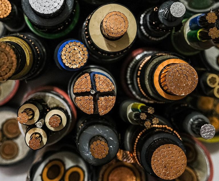
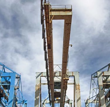
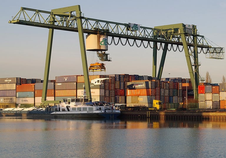
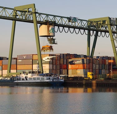
Port crane electrical systems operate under some of the most demanding conditions in industrial applications. These massive machines must lift containers weighing up to 65 tons while maintaining precise positioning control, all while exposed to harsh marine environments. The electrical cables powering these systems face constant mechanical stress, salt-laden atmospheres, and extreme current fluctuations during load operations.
Overcurrent protection serves as the primary safeguard against catastrophic failures in port crane cable systems. Without proper protection, excessive current flow can lead to insulation melting, conductor degradation, and potentially devastating electrical fires that could shut down entire port operations. The economic impact of such failures extends beyond equipment replacement costs, encompassing lost productivity, delayed cargo handling, and potential liability issues.
The complexity of port crane cable overcurrent design stems from the need to balance protection sensitivity with operational requirements. Crane motors experience significant inrush currents during startup, while the cables must handle continuous high-amperage loads during lifting operations. This dual requirement necessitates sophisticated protection schemes that can distinguish between normal operational transients and dangerous fault conditions.
Introduction: Why Is Overcurrent Protection Essential in Port Crane Cable Design?
What Is Overcurrent and How Does It Affect Port Crane Cables?
Understanding the distinction between overload and short-circuit currents forms the foundation of effective overcurrent protection design. Overload conditions occur when the current exceeds the conductor's rated capacity but remains within predictable limits, typically 125% to 600% of nominal current. These conditions develop gradually and allow time for protective intervention without immediate conductor damage.
Short-circuit currents represent far more severe conditions, often reaching thousands of amperes within milliseconds. These fault currents can cause instantaneous conductor heating that rapidly exceeds safe temperature limits, leading to insulation failure and potential fire hazards. In port crane applications, short circuits commonly result from cable damage due to mechanical stress, salt corrosion, or insulation breakdown from repetitive flexing.
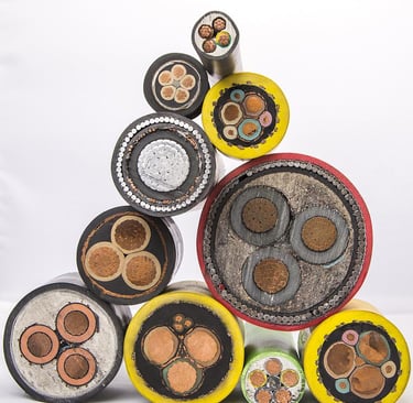
The thermal impact of overcurrent conditions varies significantly based on conductor insulation materials. According to established industry standards, different insulation types exhibit distinct temperature tolerances under normal and short-circuit conditions:
Maximum Temperature Limits for Common Insulation Types:
Polyvinyl Chloride (PVC): 70°C normal operation, 160°C short-circuit limit
Cross-Linked Polyethylene (XLPE): 90°C normal operation, 250°C short-circuit limit
Ethylene Propylene Rubber (EPR): 90°C normal operation, 250°C short-circuit limit
Silicone Rubber (SIR): 180°C normal operation, 350°C short-circuit limit
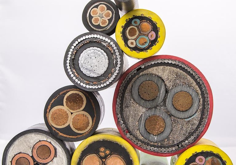
These temperature limits directly influence conductor selection for port crane applications. XLPE and EPR insulations offer superior short-circuit performance compared to PVC, making them preferred choices for high-power crane circuits. However, the selection must also consider flexibility requirements for reeling cable applications, where mechanical properties often override pure thermal considerations.

How to Calculate Short-Circuit Duration in Port Crane Cable Design
Accurate calculation of permissible short-circuit duration ensures that protective devices operate within safe thermal limits for conductors. The fundamental principle underlying these calculations assumes adiabatic conditions, where heat generated during fault conditions has insufficient time to dissipate to surrounding materials.
The standard formula for calculating maximum short-circuit duration is:
t = (k × S / I)²
Where:
t = Maximum permissible short-circuit duration (seconds)
k = Insulation-specific constant for copper conductors
S = Conductor cross-sectional area (mm²)
I = Effective short-circuit current (A)
Insulation Constants (k values) for Copper Conductors:
PVC: 115
Rubber: 143
XLPE: 143
EPR: 143
SIR: 132
Consider a practical example involving a 50mm² XLPE-insulated copper conductor in a port crane trolley feed system. If the calculated short-circuit current at the cable location reaches 8,000A, the maximum permissible fault duration becomes:
t = (143 × 50 / 8,000)² = (7,150 / 8,000)² = 0.798 seconds
This calculation demonstrates that protective devices must clear the fault within approximately 0.8 seconds to prevent conductor damage. The result emphasizes the critical importance of properly coordinated protection systems in high-fault-current environments typical of port installations.
Short-circuit calculation for port crane cable protection requires careful consideration of system impedances, including source impedance, transformer characteristics, and cable impedance from the source to the fault location. Accurate fault current calculations ensure that protective device ratings align with actual system conditions rather than conservative estimates that might compromise protection effectiveness.
What Protective Devices Are Suitable for Overcurrent Protection in Crane Systems?
The selection of appropriate protective devices for port crane overcurrent protection must satisfy multiple criteria including fault interruption capability, coordination with other protective elements, and compatibility with crane operational characteristics. International standards, particularly IEC 60269-1 for fuses and IEC 60898 for circuit breakers, provide the technical framework for device selection and application.
Fuses represent the most common overcurrent protection method in port crane applications due to their reliability, cost-effectiveness, and inherent current-limiting characteristics. The fundamental selection criterion requires that the nominal fuse current rating (Iₙ) does not exceed the conductor's current-carrying capacity (I₂), expressed as:
Iₙ ≤ I₂
This relationship ensures that the protective device operates before the conductor reaches its thermal limit under sustained overload conditions. However, the selection process must also consider the fuse's time-current characteristics to ensure compatibility with crane operational requirements.
Circuit breakers with B and C characteristics offer advantages in applications requiring frequent switching operations or where remote control capabilities are essential. B-characteristic breakers trip instantaneously at 3-5 times rated current, while C-characteristic devices operate at 5-10 times rated current. The higher pickup threshold of C-characteristic breakers makes them suitable for motor circuits experiencing significant starting currents.
The critical requirement for all protective devices in crane applications mandates that fault clearing occurs within 5 seconds to comply with adiabatic assumptions used in thermal calculations. This constraint often necessitates careful coordination between different protection levels to ensure that upstream devices do not operate before downstream protection has an opportunity to clear localized faults.
gG vs. gM Fuses: Which One Fits Port Crane Applications?
The distinction between gG (general purpose) and gM (motor protection) fuses significantly impacts their suitability for different port crane applications. Understanding their operational characteristics enables engineers to select the most appropriate protection for specific circuit requirements.
gG Fuses (General Purpose Protection): gG fuses provide comprehensive protection against both overload and short-circuit conditions, making them ideal for cable protection in distribution circuits. These devices respond relatively quickly to sustained overcurrent conditions while providing adequate short-circuit interruption capability. In port crane applications, gG fuses excel in protecting feeder cables, lighting circuits, and auxiliary power systems where motor starting transients are not a primary concern.
The time-current characteristics of gG fuses include a moderate time delay for overload conditions, allowing temporary current increases without nuisance tripping. This characteristic suits applications where brief overcurrents result from normal operational variations rather than fault conditions.
gM Fuses (Motor Protection): gM fuses specifically address the unique requirements of motor protection, particularly the high inrush currents associated with motor starting. These devices provide excellent short-circuit protection while tolerating the extended overcurrent conditions that occur during motor acceleration periods.
The key advantage of gM fuses in port crane applications lies in their ability to coordinate with thermal overload relays in motor control circuits. While the fuse provides short-circuit protection, the thermal relay handles overload protection, creating a comprehensive motor protection scheme that addresses both fast-acting faults and gradual thermal overload conditions.
Application Guidelines for Port Crane Systems:
Use gG fuses for:
Use gM fuses for:
Main feeder cables
Distribution panel protection
Transformer primary protection
Lighting and auxiliary circuits
Cable reel slip ring protection
Hoist motor circuits
Travel motor protection
Luffing motor applications
Variable frequency drive input protection
High-inertia load applications
The selection between gG and gM fuses often depends on the specific crane subsystem being protected. Main power distribution typically employs gG fuses for comprehensive protection, while individual motor circuits benefit from gM fuse characteristics that accommodate starting transients without compromising short-circuit protection.
Overcurrent Design Considerations for Harsh Port Environments
Port environments present unique challenges that significantly influence overcurrent protection design requirements. The combination of high current loads, salt-laden atmospheres, mechanical vibration, and temperature extremes demands robust protection schemes that maintain reliability under adverse conditions.
Environmental Factors Affecting Protection Design:
Salt corrosion represents a pervasive threat to electrical components in marine environments. Protective devices must feature corrosion-resistant enclosures and terminals to maintain electrical integrity throughout their service life. Stainless steel hardware and specialized coatings help mitigate corrosion effects, but proper maintenance remains essential.
Mechanical vibration from crane operations and nearby port equipment can affect protective device calibration and mechanical connections. Fuses generally exhibit superior vibration resistance compared to circuit breakers due to their simpler construction, making them preferred choices for applications subject to continuous mechanical stress.
Temperature variations, both ambient and internally generated, influence protective device performance. High ambient temperatures reduce the current-carrying capacity of both conductors and protective devices, necessitating derating calculations to ensure adequate protection under worst-case conditions.
High-Temperature Conductor Applications:
For applications where conductor temperatures may exceed 200°C during short-circuit conditions, standard tinned or bare copper conductors become inadequate. These situations require silver-plated or nickel-plated copper conductors that maintain structural integrity at elevated temperatures.
The use of enhanced conductors particularly applies to flexible reeling cables used in container crane trolley systems. These cables experience continuous flexing that can accelerate thermal degradation, making temperature-resistant conductor materials essential for reliable operation.
Flexible Cable Protection Requirements:
Overcurrent protection for flexible port crane cables must account for their unique failure modes and operational stresses. Unlike fixed installation cables, flexible cables experience mechanical wear that can gradually reduce their current-carrying capacity and increase their susceptibility to fault conditions.
Protection coordination for flexible cables often requires more conservative settings to account for reduced thermal capacity resulting from mechanical degradation. Regular cable inspection and testing programs complement overcurrent protection by identifying deteriorating cables before they reach failure conditions.
Conclusion: Best Practices for Port Crane Cable Overcurrent Design
Implementing effective overcurrent protection in port crane cable systems requires a systematic approach that integrates technical calculations, environmental considerations, and operational requirements. The following best practices ensure reliable protection while maintaining operational efficiency:
Technical Design Principles: Match protective device characteristics to specific application requirements, considering both steady-state and transient operating conditions. Utilize precise short-circuit calculations based on actual system parameters rather than conservative estimates that may compromise protection effectiveness.
Ensure that protective device ratings satisfy the fundamental relationship Iₙ ≤ I₂ while providing adequate margin for operational variations. Coordinate protection settings across multiple levels to achieve selective operation that minimizes service disruption during fault conditions.
Standards Compliance: Adhere to relevant IEC standards for fuse and circuit breaker applications, ensuring that selected devices meet performance requirements for the intended service conditions. Verify that protection schemes comply with local electrical codes and port authority safety requirements.
Maintenance and Testing: Establish comprehensive testing protocols that verify protective device operation within specified parameters. Regular inspection of cables, particularly flexible reeling cables, helps identify deteriorating conditions before they compromise protection effectiveness.
Document protection settings and coordination studies to facilitate troubleshooting and system modifications. Maintain detailed records of fault incidents to identify trends that might indicate systematic problems requiring design modifications.
Future Considerations: As port automation increases and crane systems become more sophisticated, overcurrent protection schemes must evolve to address new operational patterns and increased system complexity. Digital protection devices offer enhanced monitoring and diagnostic capabilities that can improve both protection reliability and maintenance effectiveness.
The integration of condition monitoring systems with overcurrent protection provides opportunities for predictive maintenance approaches that can prevent failures before they occur. These advanced systems represent the future direction of port crane cable overcurrent design, offering improved safety and operational efficiency through intelligent protection schemes.
Proper implementation of port crane cable overcurrent design requires balancing multiple technical and operational factors to achieve reliable protection under demanding service conditions. By following established engineering principles, adhering to relevant standards, and maintaining comprehensive testing programs, engineers can design protection systems that ensure safe, reliable crane operation while minimizing service disruptions and maintenance costs.
How to Reach Us
Get in Touch
SiteMap
Product Catalogue
Festoon Cable
Shore Power Cable


Scan to add us on WeChat