

How to Calculate Short-Circuit Current Ratings for Copper Metallic Cable Screens Using IEC 60949 Standards
Learn how to calculate permissible short-circuit current ratings for copper metallic cable screens using IEC 60949 formulas. Includes J₀ constants, adiabatic heating assumptions, and worked examples with 140 mm² screens.
hongjing.Wang@Feichun
12/26/20258 min read
Introduction
In modern power distribution systems, cable failures during short-circuit conditions can lead to catastrophic consequences—from equipment damage and fire hazards to complete system shutdowns. The metallic screens surrounding power cables serve as crucial protective elements, but their effectiveness depends entirely on their ability to withstand fault currents without thermal degradation. This is where understanding short-circuit current ratings becomes essential for electrical engineers and cable designers.
The challenge lies in determining the permissible short-circuit current that a copper metallic screen can safely handle during fault conditions. Without standardized calculation methods, engineers would be left guessing, potentially leading to either over-designed (costly) or under-designed (dangerous) cable systems. Fortunately, the IEC 60949 standard provides a scientifically rigorous and internationally recognized methodology for calculating these critical values.
This comprehensive guide will walk you through the IEC 60949 formula derivation, explain the underlying principles of adiabatic heating assumptions, and provide practical worked examples using a 140 mm² copper screen. Whether you're specifying cables for industrial installations, power distribution networks, or renewable energy projects, mastering these calculations ensures both safety and compliance with international standards.
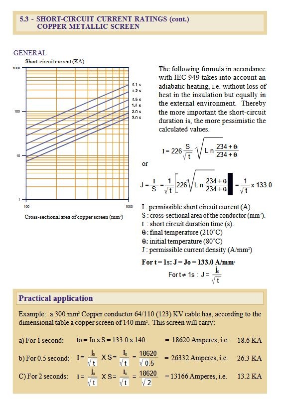
IEC 60949 is the international standard specifically developed for calculating the permissible short-circuit current ratings of metallic screens in power cables. Published by the International Electrotechnical Commission, this standard applies to various metallic screening materials, though copper remains the most common due to its excellent conductivity and thermal properties.
The primary purpose of IEC 60949 is to ensure cable safety during fault conditions by establishing a conservative calculation method. The standard recognizes that during a short-circuit event, massive currents flow through the cable screen for brief durations—typically between 0.1 and 3 seconds. During this time, the screen must maintain its structural integrity and not reach temperatures that would damage the surrounding insulation or compromise the cable's mechanical strength.
A fundamental principle underlying the IEC 60949 methodology is the adiabatic heating assumption. This conservative approach assumes that all heat generated by the fault current remains within the metallic screen conductor, with no heat dissipation to the surrounding insulation or environment. In reality, some heat transfer does occur, but this assumption provides a safety margin by calculating the worst-case scenario. For fault durations under one second, this assumption closely matches real conditions; for longer durations, it remains appropriately conservative.
The standard is particularly crucial for fault protection design in power distribution systems, where coordination between protective devices (circuit breakers, fuses, and relays) and cable ratings determines overall system reliability. Understanding the thermal withstand rating of your copper screen allows you to select appropriately sized protective equipment that will clear faults before cable damage occurs.
Understanding the IEC 60949 Standard
The Core Formula and Mathematical Framework
At the heart of IEC 60949 lies a mathematically elegant formula that relates current-carrying capacity to screen geometry, fault duration, and temperature limits:
I = 226 · S · √(ln((234 + θ_f) / (234 + θ_i)) / t)
Let's break down each component:
I represents the permissible short-circuit current in amperes (A)
S is the screen cross-section in square millimeters (mm²)
t is the fault duration in seconds (s)
θ_i is the initial temperature in degrees Celsius (°C)
θ_f is the final temperature in degrees Celsius (°C)
The constants 226 and 234 are specific copper constants derived from copper's physical properties, including its resistivity-temperature coefficient and thermal capacity. These values are unique to copper; aluminum screens, for example, would require different constants.
To understand current density (the current per unit area), we can express the formula as:
J = I / S = 226 · √(ln((234 + θ_f) / (234 + θ_i)) / t)
For standard cable screen applications, IEC 60949 typically uses an initial temperature of 80°C (representing normal operating conditions) and a final temperature of 210°C (the maximum permissible temperature that won't damage typical cable insulation). With these standard values:
ln((234 + 210) / (234 + 80)) = ln(444 / 314) = 0.348
This calculation yields J₀ = 133.0 A/mm² at t = 1 second.
This simplification allows us to use the more convenient formula:
J = 133.0 / √t
And for total current:
I = (133.0 / √t) · S
This inverse square root relationship between current and time is critical: halving the fault duration doesn't double the permissible current—it increases it by a factor of √2 (approximately 1.41). This mathematical relationship reflects the physical reality that shorter faults allow less time for heat accumulation, thus permitting higher current densities.
Step-by-Step Calculation Method
Calculating the short-circuit withstand capacity of a copper cable screen using the IEC 60949 formula is straightforward when following this systematic approach:
Step 1: Identify the Screen Cross-Section Determine the metallic screen area (S) in mm². This information should be available from cable drawings or manufacturer specifications. For woven or braided screens, use the effective metallic cross-section, not the geometric area.
Step 2: Determine Expected Fault Duration Identify the maximum fault clearing time (t) based on your protection scheme. This depends on circuit breaker or fuse characteristics and relay settings. Common values range from 0.1 to 3.0 seconds. Conservative design uses the longest expected clearing time.
Step 3: Confirm Temperature Limits For standard applications, use θ_i = 80°C and θ_f = 210°C. If your cable operates in unusual conditions (very high ambient temperatures or special insulation materials), you may need custom values.
Step 4: Calculate J₀ for Non-Standard Temperatures If using non-standard temperature limits, compute J₀ using the natural logarithm formula. Otherwise, use the standard value of 133.0 A/mm².
Step 5: Apply the Simplified Formula For standard temperatures, calculate current density: J = 133.0 / √t
Step 6: Calculate Total Current Multiply by screen area: I = J · S
Step 7: Convert to Practical Units Express the result in kiloamperes (kA) for easier comparison with protection device ratings: I(kA) = I(A) / 1000
Quick Reference Values:
At t = 0.5s: J = 188.1 A/mm²
At t = 1.0s: J = 133.0 A/mm²
At t = 2.0s: J = 94.0 A/mm²
When selecting screen sizes during cable specification, engineers typically work backwards: given the expected fault current from system studies and the protection clearing time, calculate the minimum required screen cross-section to safely withstand the fault.
Worked Example: 140 mm² Copper Screen
Let's apply the IEC 60949 method to a practical case: a copper metallic screen with a cross-section of 140 mm². This is a common size for medium-voltage power cables in industrial and utility applications.
Case 1: Fault Duration of 1.0 Second
Using the standard J₀ = 133.0 A/mm²:
I₀ = 133.0 × 140 = 18,620 A = 18.6 kA
This means the 140 mm² copper screen can safely withstand a short-circuit current of 18.6 kiloamperes for exactly one second without exceeding the 210°C temperature limit. This value serves as the reference point for other durations.
Case 2: Fault Duration of 0.5 Seconds
For shorter faults, the permissible current increases:
I = 18,620 / √0.5 = 18,620 / 0.707 = 26,332 A = 26.3 kA
The shorter fault duration allows approximately 41% higher current because there's less time for heat accumulation. This is particularly relevant for systems with fast-acting protection, such as electronic relays or current-limiting circuit breakers.
Case 3: Fault Duration of 2.0 Seconds
For longer faults, the safe current decreases:
I = 18,620 / √2 = 18,620 / 1.414 = 13,166 A = 13.2 kA
This inverse relationship with √t is fundamental to fault protection coordination. If your protection system takes 2 seconds to clear a fault, the screen can only handle 13.2 kA—29% less than the 1-second rating.
Practical Application: When specifying this cable, an engineer would compare these values against the maximum available fault current at the installation point (obtained from power system studies). If the fault current could reach 20 kA and the protection clears in 1 second, this 140 mm² screen would be inadequate—a larger screen would be required.


Key Considerations and Limitations
While the IEC 60949 adiabatic heating method is robust and widely accepted, understanding its limitations ensures appropriate application:
Adiabatic Assumption Limitations: The assumption of no heat dissipation is conservative but not always accurate. For very short faults (under 0.1 seconds), it's highly accurate. For faults exceeding 2-3 seconds, some heat does dissipate, making the calculation overly conservative. However, this built-in safety margin is generally desirable.
Temperature Limit Selection: The standard 80°C-210°C range suits most cable types, but specific applications may require adjustment. For example:
Cables in very hot environments (desert installations) might start at 100°C
Cables with premium insulation might allow 250°C final temperature
XLPE-insulated cables commonly use 90°C-250°C
For custom temperature ranges, recalculate J₀ using the full logarithmic formula.
Material-Specific Constants: The copper-specific constants (226 and 234) cannot be applied to aluminum or steel screens. Aluminum requires constants 148 and 228, reflecting its different thermal properties. Always verify you're using the correct material constants.
Design Safety Margins: Practical engineering typically applies additional safety factors beyond the IEC calculation:
10-20% derating for uncertainties in screen manufacturing tolerances
Consideration of repeated fault duty (multiple faults over cable lifetime)
Accounting for thermal aging of insulation
Protection Device Coordination: The calculated screen rating must align with the time-current characteristics of protective devices. A 20 kA fault current rating at 1 second is meaningless if your circuit breaker takes 1.5 seconds to clear that current level.
Applications Across Industries
The IEC 60949 calculation method finds application across numerous sectors where reliable cable fault protection is critical:
Power Distribution Systems: Utility companies use these calculations when specifying medium-voltage cables (11kV to 33kV) for substations and distribution feeders. With available fault currents often exceeding 25 kA, proper screen sizing is essential.
Industrial Control Cables: Manufacturing facilities, petrochemical plants, and process industries use multi-conductor screened cables where the metallic shield provides both electromagnetic shielding and fault protection. The screen must handle ground fault currents safely.
Renewable Energy Installations: Wind farms and solar power plants require extensive cable networks where fault current levels can be substantial. Array cables, collector cables, and export cables all need IEC 60949 verification during the cable specification process.
Marine and Offshore Applications: Subsea cables and shipboard power systems face stringent fault protection requirements due to the difficulty of repairs and fire safety concerns. The conservative IEC approach suits these demanding environments.
Telecommunications Infrastructure: While telecom cables operate at lower voltages, lightning-induced surges can create substantial fault currents in cable screens. IEC 60949 helps size screens for surge protection.
Cable Specification Process: During procurement, engineers reference IEC 60949 calculations in technical specifications, requiring manufacturers to provide test certificates demonstrating compliance. This ensures cables meet thermal withstand requirements before installation.
Common Questions and Problem Scenarios
Q: What happens if the actual fault current exceeds the calculated rating? If fault current exceeds the screen's rating, several failure modes are possible: insulation damage from excessive heat, screen melting or burning, cable fire, or even explosive failure in extreme cases. This is why conservative calculations and proper protection coordination are essential.
Q: Can I use the same screen for different voltage levels? The screen's short-circuit rating is independent of operating voltage—it depends only on current and duration. However, voltage affects insulation thickness and overall cable geometry, which indirectly impacts available space for the screen.
Q: How do I handle cables with multiple parallel screens? For cables with concentric layers (outer screen plus inner shields), sum the cross-sections of all metallic layers that carry fault current. Ensure good electrical continuity between layers.
Q: What if my protection device has an uncertain clearing time? Use the maximum clearing time from the device characteristic curve at the expected fault current level. If the time varies significantly, calculate for the longest duration—this gives the most conservative result.
Q: Should I derate for ambient temperature? The initial temperature (θ_i) accounts for ambient effects. If your cable operates in a 50°C ambient versus 30°C, adjust θ_i upward accordingly. The cable conductor temperature under normal load determines
Conclusion and Engineering Best Practices
The IEC 60949 standard provides electrical engineers with a mathematically rigorous, internationally recognized method for calculating short-circuit current ratings of copper metallic cable screens. The core formula—I = 226 · S · √(ln((234 + θ_f) / (234 + θ_i)) / t)—elegantly captures the relationship between screen geometry, fault duration, and thermal limits.
For standard conditions (80°C to 210°C), the simplified expression J = 133.0 / √t offers a practical tool for quick calculations, while the worked examples with 140 mm² screens demonstrate real-world application. Whether dealing with 18.6 kA at 1 second or 26.3 kA at 0.5 seconds, the inverse square root relationship with time remains fundamental to understanding cable thermal behavior during faults.
Key engineering takeaways include:
Always verify calculated ratings against system fault studies and protection device characteristics
Use the adiabatic method as a conservative baseline, adding safety margins for critical applications
Coordinate cable selection with protection clearing times—faster protection allows smaller, more economical screens
Document all assumptions, particularly temperature limits and fault durations, in specifications
As electrical systems become more complex and fault currents continue rising with increasing power demand, rigorous application of IEC 60949 standards ensures copper screen safety and system reliability. Master these calculation methods, understand their limitations, and apply them consistently throughout the cable selection and verification process for optimal fault protection design.
How to Reach Us
Get in Touch
SiteMap
Product Catalogue
Festoon Cable
Shore Power Cable




Scan to add us on WeChat