

ISO/IEC 11801 Standard: Complete Guide to Structured Cabling, Category Cable Types, and Optical Fiber Specifications
Learn about ISO/IEC 11801 structured cabling standards for commercial buildings and industrial networks. Explore copper cable categories (Cat 5e to Cat 8), optical fiber classes (OM1-OM5, OS1-OS2), shielding types, and technical specifications for 10G/40G Ethernet installations.
hongjing.Wang@Feichun
12/12/20258 min read
Decoding Network Cabling Categories: From Cat 5e to Cat 8
The ISO/IEC 11801 structured cabling standard defines multiple classes of twisted pair cables, each corresponding to specific performance characteristics and frequency capabilities. Understanding these network cabling categories is essential for anyone planning, installing, or maintaining modern communication infrastructure.
Foundation Categories: Building Blocks of Copper Cabling
The classification system begins with Class A through Class D, representing progressively higher frequency capabilities. Class A operates up to 100 kHz using Category 1 components, while Class B extends to 1 MHz with Category 2 cable. Class C, utilizing Category 3 cable and connectors, supports frequencies up to 16 MHz—sufficient for traditional voice telephony and basic data applications.
Class D represents a significant milestone, employing Category 5e cable specifications that support frequencies up to 100 MHz. This category became the de facto standard for gigabit Ethernet deployments in commercial buildings, offering a balance between performance and cost that made it ubiquitous in office environments worldwide. Class E, using Category 6 cable, pushes this boundary to 250 MHz, providing additional headroom for emerging applications.
High-Performance Categories: Meeting Modern Bandwidth Demands
As network speeds increased, the industry demanded copper cabling systems capable of supporting 10 gigabit Ethernet and beyond. This need drove the development of several advanced categories, each addressing specific technical challenges.
Category 6A represents Class EA channels operating at frequencies up to 500 MHz. This Category 6A 10 gigabit Ethernet copper cabling solution became widely adopted because it maintained compatibility with the standard 8P8C connector (commonly called RJ45), allowing organizations to upgrade to 10 Gigabit Ethernet without replacing their entire connector infrastructure.
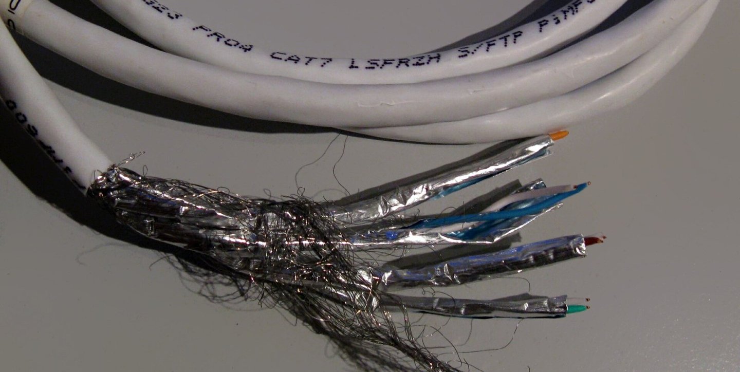
Category 7 cable specifications define Class F channels supporting frequencies up to 600 MHz. Ratified in 2002, Category 7 introduced a fundamental shift in design philosophy by incorporating comprehensive shielding. Unlike unshielded cables that rely solely on the quality and tightness of wire pair twists to protect against electromagnetic interference (EMI), Category 7 employs both individual shielding for each wire pair and an overall cable shield. This dual-layer protection significantly reduces crosstalk and system noise.
The shielded design allows Category 7 cables to use longer twist lengths per pair, as the metallic shielding provides the primary EMI protection. These cables support 10 gigabit Ethernet over the full 100-meter horizontal cabling distance and are terminated with specialized GG45 or TERA connectors rated for transmission frequencies up to 600 MHz. However, it's important to note that Category 7 is not recognized by the TIA/EIA standards bodies commonly referenced in North America.
Category 7A cable (Class FA or Class F Augmented) was introduced through ISO 11801 Edition 2 Amendment 2 in 2010, extending frequency support up to 1000 MHz. This specification was initially intended to support future 40 gigabit Ethernet implementations, with simulation results suggesting 40GBASE-T might be achievable at 50 meters and even 100 gigabit Ethernet at 15 meters. The enhanced bandwidth also makes Category 7A suitable for applications including CATV distribution at 862 MHz.
However, the anticipated Category 7A cable advantages over Category 8 cabling didn't materialize as expected. When the IEEE 802.3bq working group ratified 25GBASE-T and 40GBASE-T standards in 2016, they specified Category 8 cabling instead, which offered superior performance at 2000 MHz. As of recent years, virtually no active equipment has been manufactured with connectors supporting Class FA channels, and like Category 7, Category 7A lacks TIA/EIA recognition.
Category 8 Cable: The Current Frontier
Category 8 cabling represents the current pinnacle of copper twisted-pair technology. Ratified by the TR43 working group under ANSI/TIA 568-C.2-1, this next-generation high-frequency cabling operates at frequencies up to 2000 MHz—four times the bandwidth of Category 6A.
The standard defines two distinct implementations:
Class I channels use Category 8.1 cable with a minimum design specification of U/FTP (unshielded overall, foil-shielded pairs) or F/UTP (foil-shielded overall, unshielded pairs). This configuration maintains full backward compatibility with Class EA (Category 6A) infrastructure and uses standard 8P8C connectors, allowing seamless integration with existing Category 6A installations.
Class II channels employ Category 8.2 cable specifications requiring F/FTP (foil overall, foil pairs) or S/FTP (braided overall, foil pairs) minimum construction. These cables maintain compatibility with Class FA (Category 7A) systems and utilize TERA or GG45 connectors.
The primary limitation of Category 8 is distance. Due to the extremely high frequencies involved, these systems are specified for distances of only 30 to 36 meters, depending on the patch cords used. This Category 8.1 and 8.2 cable differences make them ideal for data center top-of-rack switching and other short-distance, high-bandwidth applications, but unsuitable for traditional horizontal cabling in office environments.
All these copper cabling systems maintain a standard link impedance of 100 Ω, ensuring consistent electrical characteristics across the infrastructure.
Understanding the Foundation of Modern Network Infrastructure
In today's interconnected world, reliable network infrastructure forms the backbone of virtually every commercial, industrial, and residential facility. Whether you're streaming a video conference in an office building, monitoring automated systems in a manufacturing plant, or simply browsing the internet at home, you're relying on carefully engineered cabling systems. The ISO/IEC 11801 standard serves as the global blueprint for these critical structured cabling systems, ensuring consistent performance and compatibility across diverse applications.
Published jointly by the International Organization for Standardization (ISO) and the International Electrotechnical Commission (IEC) through their JTC 1/SC 25/WG 3 working group, this comprehensive standard addresses both copper cabling systems and optical fiber specifications. It provides the technical framework for telecommunications cabling that supports an impressive range of applications—from traditional analog telephony and ISDN systems to high-speed data communication, building control systems, and factory automation networks.
The standard was originally designed for commercial premises, whether a single building or an entire campus. While optimized for facilities spanning up to 3 kilometers, covering up to 1 square kilometer of office space, and serving between 50 and 50,000 users, ISO/IEC 11801 can be adapted for installations outside these parameters. A major revision released in November 2017 unified requirements across commercial, home, and industrial networks, reflecting the growing convergence of these previously distinct environments.


Understanding Shielded Twisted Pair Cable Types Explained
One of the most frequently asked questions about structured cabling concerns the various shielding configurations available. The ISO 11801 building cabling system requirements address this through Annex E, which provides a systematic acronym system for specifying exact cable construction.
The nomenclature uses three letters—U for unshielded, S for braided shielding, and F for foil shielding—in a two-part abbreviation format: xx/xTP. The first part indicates overall cable shielding, while the second part specifies individual pair shielding.
Common configurations include:
U/UTP: Completely unshielded cables, relying entirely on wire pair twisting for EMI protection
U/FTP: Individual foil shielding for each pair without overall cable screening
F/UTP, S/UTP, SF/UTP: Overall cable screening without individual pair shielding
F/FTP, S/FTP, SF/FTP: Complete shielding systems with both overall cable screens and individual pair foil shielding
The choice between these configurations depends on your electromagnetic environment. Industrial facilities with heavy machinery, medical centers with sensitive equipment, or installations near radio frequency sources typically require shielded designs to prevent interference. Standard office environments often perform adequately with unshielded Category 6A, while data centers increasingly specify Category 8 with its mandatory shielding for maximum performance.


Optical Fiber Specifications: The High-Bandwidth Alternative
While copper twisted-pair cables excel at shorter distances, optical fiber interconnect classes provide superior performance for longer runs and higher bandwidths. The ISO/IEC 11801 standard for electrical and optical cable defines several fiber classifications based on core diameter, modal bandwidth, and attenuation characteristics.
Multimode Fiber: Versatile and Cost-Effective
Multimode fibers use larger core diameters that allow multiple light modes to propagate simultaneously:
OM1 fibers feature a 62.5 μm core diameter with a minimum modal bandwidth of 200 MHz·km at 850 nm wavelength. While historically common, OM1 has been largely superseded by higher-performance options.
OM2 maintains a 50 μm core diameter but increases the minimum modal bandwidth to 500 MHz·km at 850 nm, providing better performance for moderate-speed applications.
OM3 and OM4 represent laser-optimized multimode fibers, both with 50 μm cores. OM3 delivers a minimum modal bandwidth of 2000 MHz·km at 850 nm, while OM4 dramatically increases this to 4700 MHz·km at the same wavelength. These specifications make OM4 suitable for 10 Gigabit Ethernet up to 550 meters and even 100 Gigabit Ethernet up to 150 meters.
OM5 fiber multimode cable bandwidth introduces a revolutionary capability: wideband operation across multiple wavelengths. While maintaining the 4700 MHz·km bandwidth at 850 nm like OM4, OM5 adds a specification of 2470 MHz·km at 953 nm. This dual-wavelength capability enables Shortwave Wavelength Division Multiplexing (SWDM) technology.
SWDM multiplexing allows OM5 fibers to carry 4 to 16 distinct wavelength carriers in the 850-953 nm range. This enables remarkably efficient bandwidth utilization: 40G implementation using four wavelengths at 10G each (4λ × 10G), 100G using four wavelengths at 25G each (4λ × 25G), and even 400G using four fibers each carrying four wavelengths at 25G (4 × 4λ × 25G). This generic cabling for customer premises standard makes OM5 an increasingly attractive option for future-proofing network installations.
Single-Mode Fiber: Long-Distance Champions
Single-mode fibers use much smaller core diameters (typically 9 μm) that allow only a single light mode, dramatically reducing signal dispersion and enabling longer transmission distances.
OS1 specifies maximum attenuation of 1 dB/km at both 1310 nm and 1550 nm wavelengths. The enhanced OS1a variant adds support for the 1383 nm wavelength, eliminating the water peak attenuation issue that affected earlier fiber designs.
OS2 represents the current premium single-mode specification, with maximum attenuation of just 0.4 dB/km at 1310, 1383, and 1550 nm. This low attenuation enables transmission distances of tens of kilometers without signal regeneration, making OS2 ideal for campus backbone networks, metropolitan area networks, and telecommunications infrastructure.
Practical Application Scenarios: Choosing the Right Cable
Understanding these specifications becomes practical when considering real-world scenarios:
Scenario 1: Office Building Retrofit A mid-sized company needs to upgrade their 20-year-old Category 5 infrastructure. While Category 6A would provide adequate 10 Gigabit Ethernet support, specifying OM4 or OM5 fiber for vertical risers and horizontal runs to server rooms offers better future-proofing for potential 40G or 100G upgrades, while Category 6A serves desktop connections.
Scenario 2: Data Center Design A new colocation facility requires maximum performance in confined spaces. Category 8.1 cabling provides 25G and 40G support for top-of-rack connections within its 30-meter limit, while OM5 fiber handles all longer inter-rack and backbone connections, providing a clear migration path to 400G technologies.
Scenario 3: Industrial Environment A manufacturing facility needs reliable connectivity despite significant electromagnetic interference from machinery. S/FTP or SF/FTP shielded cables (Category 7 or 7A) provide robust protection against EMI, while fiber optic connections eliminate electrical interference concerns entirely for critical control systems.
Common Problems and Solutions
Problem: Signal degradation when mixing cable categories Solution: Maintain consistent category specifications throughout each channel. A single Category 5e connector in an otherwise Category 6A channel reduces the entire link to Category 5e performance. Always verify that connectors, patch panels, and cables all meet the same minimum specifications.
Problem: Electromagnetic interference affecting network stability Solution: Conduct a site survey to identify interference sources. In high-EMI environments, specify shielded cabling with proper grounding at both ends. Alternatively, consider optical fiber, which is immune to electromagnetic interference.
Problem: Insufficient bandwidth for future applications Solution: When specifying new installations, consider bandwidth requirements 10-15 years forward. The incremental cost of Category 6A over Category 6, or OM5 over OM3, is minimal during initial installation but provides significantly better future-proofing. The cost of recabling far exceeds the initial premium for higher-grade materials.
Conclusion: Building Infrastructure for Tomorrow
The ISO/IEC 11801 standard provides the essential framework for modern structured cabling systems, defining clear performance criteria from Category 5e through Category 8 for copper installations and OM1 through OS2 for optical fiber networks. By understanding these specifications—including the technical nuances of Category 7 vs Category 8 cable specifications, the benefits of OM5 fiber technology, and the importance of proper shielding selection—network professionals can design and implement infrastructure that delivers reliable performance today while accommodating tomorrow's bandwidth demands.
Whether you're specifying cabling for a small office, a sprawling campus, or a high-performance data center, adherence to ISO/IEC 11801 standards ensures your investment in network infrastructure delivers optimal performance, maintains compatibility with diverse equipment, and provides the scalability necessary for evolving technology requirements. The key lies not just in selecting the highest category available, but in thoughtfully matching cable specifications to your specific application requirements, electromagnetic environment, distance constraints, and future growth projections.
How to Reach Us
Get in Touch
SiteMap
Product Catalogue
Festoon Cable
Shore Power Cable




Scan to add us on WeChat