
(K) NSHTOEU Flexible Low Voltage Reeling Cable: Comprehensive Technical Guide for Medium Mechanical Stress Applications
NSHTOEU flexible low voltage reeling cable for medium mechanical stresses. Durable, versatile crane and material handling power cable. Technical specs & applications.
hongjing.Wang@Feichun
11/27/202520 min read
Introduction to NSHTOEU Reeling Cable Technology
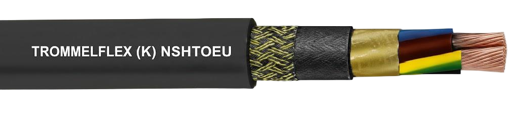
The NSHTOEU flexible low voltage reeling cable represents a specialized solution engineered for industrial environments requiring reliable power transmission under medium mechanical stress conditions. This cable designation refers to a robust, rubber-sheathed flexible power cable specifically designed for crane systems, material handling equipment, and mobile industrial machinery where consistent electrical performance must be maintained through repeated flexing, bending, and moderate tensile loads.
Unlike entry-level flexible cables that may struggle with demanding industrial conditions or heavy-duty specifications that exceed requirements for many applications, the NSHTOEU cable occupies an optimal middle ground. This positioning makes it particularly valuable for facilities seeking dependable performance without over-engineering their electrical infrastructure. The cable's construction according to DIN VDE 0250-814 standards ensures consistent quality and performance characteristics across manufacturing batches.
The NSHTOEU designation itself follows German electrical engineering nomenclature where each letter indicates specific construction elements: N indicates standard design compliance, S refers to heavy rubber insulation, H designates heavy rubber sheathing, T indicates tensile-resistant construction, Ö represents oil-resistant properties, and U confirms flame-retardant characteristics. This systematic naming convention allows electrical engineers to quickly identify cable capabilities before reviewing detailed specifications.
Technical Specifications and Electrical Performance Parameters
Voltage Ratings and Electrical Characteristics
The NSHTOEU low voltage reeling cable operates at a rated voltage of 0.6/1 kV, providing dual voltage designation where 0.6 kV represents the voltage between conductor and ground, while 1 kV indicates the voltage between conductors. This configuration accommodates both 600V and 1000V system requirements commonly found in industrial facilities worldwide.
Maximum permissible operating voltage extends to 0.7/1.2 kV for alternating current applications, offering a 20% safety margin above rated voltage—a critical buffer protecting against voltage transients and surges typical in industrial power distribution systems. For direct current installations, the cable supports up to 0.9/1.8 kV, reflecting the 1.5x multiplier standard for DC systems due to their different stress characteristics on insulation materials.
AC test voltage capability reaches 2.5 kV sustained for five minutes, demonstrating substantial dielectric strength margins. This testing protocol, performed during manufacturing quality assurance processes, verifies insulation integrity and identifies potential weak points before cables enter service. The robust test voltage significantly exceeds operating conditions, providing confidence in long-term insulation performance even as materials age.
Current carrying capacity follows DIN VDE 0298-4 methodology, accounting for conductor cross-section, installation method, ambient temperature, and conductor material properties. For rubber-insulated cables laid on surfaces at 30°C ambient temperature, capacity ranges from 23A for 1.5mm² conductors to 540A for 240mm² power cores. These ratings assume continuous duty cycles; intermittent applications with cooling periods permit higher loading through appropriate de-rating factor applications.
Mechanical Properties and Load Specifications
The cable's mechanical characteristics define its suitability for reeling applications under medium stress conditions. Maximum tensile load capacity of 15 N/mm² represents the force per unit conductor cross-section that the cable can safely withstand during operation. For a 50mm² conductor, this translates to 750N (approximately 76kg force)—adequate for typical gantry crane installations with proper cable management systems.
Torsional stress tolerance of ±50°/m allows the cable to accommodate twisting forces encountered during cable routing through complex pathways or when reeling systems experience slight misalignment. This specification becomes particularly relevant in festoon systems where cable undergoes continuous twisting and untwisting through operational cycles. The polyester braid reinforcement embedded within the sheath structure provides this torsional stability by resisting rotational forces that would otherwise cause conductor spiraling.
Minimum bending radius requirements follow DIN VDE 0298 part 3 guidelines, typically calculated as multiples of overall cable diameter. For fixed installations, the minimum radius generally equals 3-4 times cable diameter, while fully flexible operations require 5 times diameter to prevent internal stress concentrations. S-type directional changes—where cable reverses direction—demand minimum spacing of 20 times diameter between bending points to avoid cumulative fatigue.
Travel speed capability up to 120 m/min accommodates standard reeling operation speeds found in material handling applications. This velocity represents the linear speed at which cable unreels or recoils without exceeding mechanical stress limits or generating excessive heat through friction. Higher speeds risk accelerated wear, conductor fatigue, and premature insulation breakdown, making proper speed consideration essential during system design.
Thermal Parameters and Temperature Operating Ranges
Maximum permissible conductor temperature of 90°C during normal operation reflects the thermal capability of the 3GI3 rubber insulation compound. This temperature limit considers both internal heat generation from current flow (I²R losses) and external ambient temperature contributions. Continuous operation at elevated temperatures accelerates insulation aging through oxidation and polymer chain breakdown, making thermal management critical for longevity.
Short circuit temperature capability reaches 250°C, representing the maximum temperature conductors can briefly withstand during fault conditions before insulation damage occurs. This specification typically assumes a one-second fault duration—the expected clearing time for properly coordinated protective devices. The substantial margin between operating and short-circuit temperatures provides safety buffers during abnormal conditions.
Ambient temperature range for fixed installation spans -40°C to +80°C, accommodating extreme environmental conditions from Arctic facilities to tropical industrial environments. However, the fully flexible operation range narrows to -25°C to +80°C due to increased mechanical stress on materials during low-temperature bending. Below -25°C, rubber compounds exhibit reduced flexibility, potentially leading to insulation cracking during flexing operations.
Construction Design and Material Composition
Conductor Specifications and Manufacturing
NSHTOEU cables utilize tinned copper conductors manufactured to flexible class 5 specifications per DIN EN 60228 and DIN VDE 0295 standards. Class 5 conductors contain numerous fine wire strands—typically ranging from 60 strands for 1.5mm² conductors to over 1000 strands for 240mm² configurations. This fine stranding provides the flexibility essential for reeling applications while maintaining electrical conductivity.
Tinning applies a thin coating of pure tin over copper strands, providing multiple performance benefits. The tin layer prevents copper oxidation, maintaining low contact resistance at terminations throughout the cable's service life. In humid or chemically aggressive environments, tinning offers additional corrosion protection. The tin coating also facilitates soldering during termination procedures, though modern crimp terminations have largely superseded soldered connections in industrial installations.
Maximum conductor resistance values specified at 20°C range from 13.3 Ω/km for 1.5mm² conductors to 0.08 Ω/km for 240mm² conductors. These resistance values directly impact voltage drop calculations—critical for ensuring adequate voltage delivery to connected equipment, particularly in long cable runs. Temperature coefficient considerations adjust these resistance values for operating temperatures above or below the 20°C reference.
Insulation System and Core Identification
The insulation system employs rubber compound type 3GI3 according to DIN VDE 0207-20, a specialized ethylene propylene rubber (EPR) formulation optimized for flexible cable applications. This compound delivers superior mechanical characteristics compared to standard rubber, including enhanced tear resistance, improved low-temperature flexibility, and excellent aging properties when exposed to ozone and ultraviolet radiation.
Core identification follows established color coding conventions facilitating installation and maintenance. Cables with five or fewer cores utilize full color coding per DIN VDE 0293-308: brown, black, blue, green-yellow (protective earth), and grey. This standardized scheme enables quick visual identification during termination and troubleshooting. Configurations exceeding five cores employ black insulation with white-printed sequential numbers, maintaining clear identification while economizing on specialized colored compounds.
The protective earth conductor consistently receives green-yellow color identification regardless of core count, ensuring immediate recognition of this safety-critical conductor. In power cable configurations, the earth conductor may be split into three sections (designated 3G or 3x25/3) distributed through the cable geometry, improving mechanical balance and providing redundant earth paths.
Core Arrangement and Internal Structure
Core arrangement significantly influences cable flexibility and mechanical stability. A central filler—constructed from plastic or textile materials and potentially rubber-coated—occupies the cable's geometric center, around which cores are twisted at short lay lengths. This twisted arrangement, rather than parallel core orientation, distributes bending stresses evenly across all conductors and prevents individual core stress concentration.
The lay length (distance over which cores complete one full revolution around the cable axis) typically measures 7 times the cable's overall diameter for NSHTOEU constructions. Shorter lay lengths increase flexibility but reduce tensile strength, while longer lays improve strength at the expense of bending ease. The 7x diameter specification represents an optimized compromise for medium-stress reeling applications.
Inner sheath construction utilizes rubber compound type 5GM3 per DIN VDE 0207-21, providing a resilient cushion between the core assembly and reinforcement braid. This layer maintains core geometry during flexing, prevents individual core movement that could cause internal abrasion, and creates a seal against moisture ingress. The compound's mechanical properties complement those of the insulation and outer sheath.
Reinforcement and Outer Sheath System
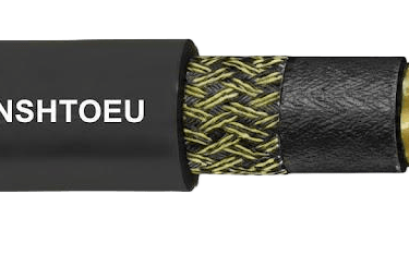
A wide-meshed polyester braid embedded within the sheath structure provides anti-torsion properties and enhances tensile strength without significantly reducing flexibility. The braid's open weave allows rubber compound penetration during vulcanization, creating a unified structure where the braid is firmly bonded within the sheath system rather than functioning as a loose layer. This integration prevents braid slippage during torsional loads.
The outer sheath employs extruded rubber compound type 5GM5 according to DIN VDE 0207-21, selected specifically for its abrasion resistance, tear propagation resistance, and oil-resistant properties. The compound formulation balances multiple performance requirements: sufficient flexibility for repeated bending, adequate hardness to resist mechanical damage, and chemical resistance to industrial contaminants.
Black coloring with white marking provides maximum contrast for cable identification while offering practical advantages. Black pigmentation (typically carbon black) improves UV resistance and thermal stability. White printing displays the NSHTOEU designation, core configuration (e.g., "4x2.5" indicating four 2.5mm² conductors), voltage rating, and week/year manufacturing code, facilitating cable identification during installation and maintenance.

Industrial Applications and Operating Environments
Crane Systems and Material Handling Equipment
NSHTOEU flexible reeling cable for crane applications represents one of the primary use cases for this cable specification. Gantry cranes in shipping terminals, rail yards, and manufacturing facilities require reliable power delivery as the crane traverses along runways spanning hundreds of meters. The cable unreels from a drum as the crane moves in one direction and recoils as it returns, experiencing thousands of reeling cycles annually.
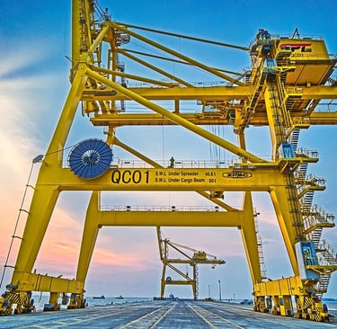
Container handling systems in modern ports present particularly demanding applications. Rubber-tyred gantry cranes (RTGs) may move at speeds approaching the cable's 120 m/min rating while supporting electrical loads exceeding 100kW. The NSHTOEU cable's medium mechanical stress capability suits these applications when cable management systems properly control tensile loads and bending radii through appropriate drum sizing and festoon system design.
Overhead traveling cranes in manufacturing facilities utilize these cables for both power and control circuits. A typical installation might employ a 4x25mm² NSHTOEU cable for main power delivery complemented by a 24x1.5mm² control cable configuration for pushbutton stations, limit switches, and control signaling. The consistent mechanical characteristics across power and control configurations simplify installation and maintenance procedures.
Reeling Systems and Cable Guidance Mechanisms
Cylindrical reels represent the most common cable guidance method for NSHTOEU applications. The cable wraps in neat layers around a rotating drum, with careful attention to drum diameter ensuring minimum bending radius requirements are satisfied. Spring-loaded or motor-driven constant-tension systems maintain proper cable tensioning throughout the unwinding and rewinding process, preventing slack that could cause cable damage through entanglement or crushing between drum flanges and adjacent cable layers.
Festoon systems offer an alternative guidance method where the cable hangs in a series of loops supported by trolleys rolling along a conductor bar or track. While NSHTOEU cables can function in festoon applications at moderate speeds, their construction optimization for reeling means alternative specifications may prove more suitable for high-speed festoon systems or applications with frequent directional reversals.
Cable tenders—motorized cable management systems that actively pay out and retrieve cable length in response to equipment movement—work effectively with NSHTOEU cables in specialized applications. The tender maintains consistent cable tension and controls deployment speed independently of equipment motion, reducing mechanical stress compared to direct reeling arrangements. This approach extends cable service life in particularly demanding installations.
Environmental Operating Conditions
Outdoor installations expose cables to weather extremes testing thermal and environmental resistance specifications. In northern industrial facilities, winter temperatures may approach the cable's -25°C lower operating limit during flexible operation. Summer conditions in desert or tropical environments can see ambient temperatures exceeding 40°C, requiring careful current capacity de-rating to prevent conductor temperatures from approaching 90°C limits.
Industrial environments frequently present chemical exposure hazards. The NSHTOEU cable's oil resistance according to EN 60811-404 (tested with ASTM Oil No. 2 at 100°C for 24 hours) provides protection against hydraulic fluids, lubricating oils, and petroleum-based contaminants commonly encountered in manufacturing and material handling facilities. However, continuous immersion in aggressive chemicals or solvents may degrade rubber compounds, necessitating specific chemical compatibility verification.
UV radiation and ozone exposure represent environmental factors affecting outdoor cable installations. Rubber compounds are inherently susceptible to ozone attack, which causes surface cracking and eventual insulation breakdown. The 5GM5 outer sheath compound includes antioxidant and anti-ozonant additives providing unrestricted outdoor use capability, though periodic inspection for surface checking remains prudent in high-ozone environments near electrical equipment generating corona discharge.
Available Configurations and Sizing Options
Control Cable Configurations
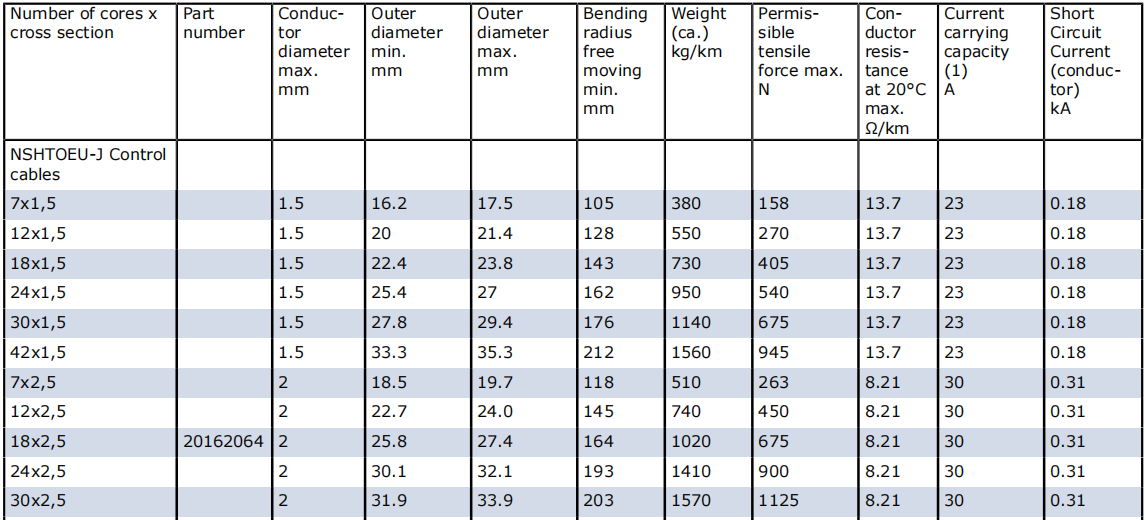
Control cable variants span from compact 7x1.5mm² configurations suitable for pushbutton stations and pilot circuits to substantial 42x2.5mm² assemblies accommodating complex control panels with numerous circuits. The multicore designs consolidate multiple control circuits within a single cable, simplifying installation compared to running separate cables for each circuit while reducing overall material costs.
Smaller control configurations (12x1.5mm² to 18x1.5mm²) commonly serve control panels on mobile equipment, providing circuits for emergency stops, directional controls, indicator lamps, and interlock signals. Medium-sized configurations (24x1.5mm² to 30x2.5mm²) accommodate more complex control requirements including analog signals, communication circuits, and redundant safety systems.
Bus cable configurations with twisted and shielded pairs support digital communication protocols. Options such as 6x(2x1)C or 12x(2x1)C provide controlled impedance pathways for Profibus, CANbus, or similar industrial networks. The individual pair shielding minimizes electromagnetic interference from adjacent power conductors, maintaining signal integrity in electrically noisy industrial environments.
Power Cable Configurations
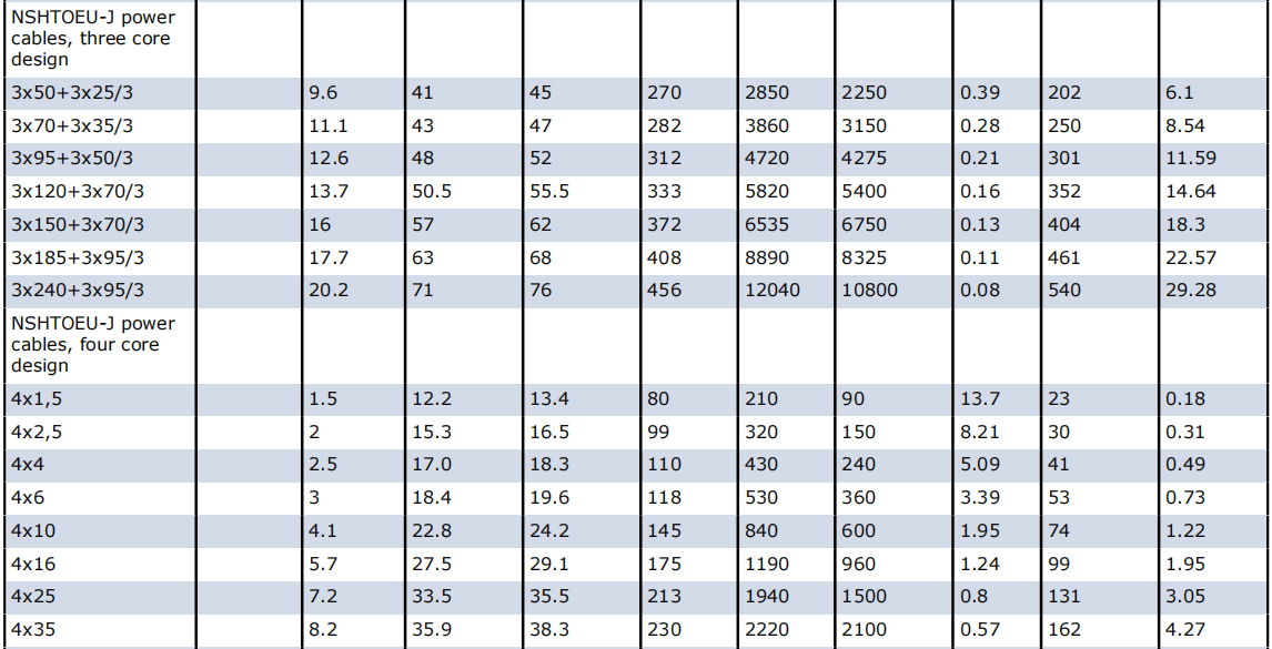
Three-core power cable designs with split earth conductors (designated 3x50+3x25/3, for example) optimize weight and flexibility while maintaining earth continuity through three earth strands distributed through the cable geometry. This configuration particularly suits applications where protective earth conductor sizing may be reduced compared to phase conductor sizes per electrical codes allowing proportional earth conductor sizing.
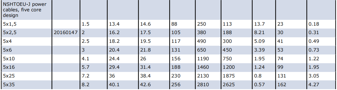
Four-core power cables ranging from 4x1.5mm² to 4x35mm² accommodate three-phase systems with neutral or three-phase systems with protective earth configurations. The symmetrical conductor arrangement maintains mechanical balance during flexing, preventing preferential bending directions that might accelerate wear. Standard configurations include 4x4mm², 4x6mm², 4x10mm², and 4x16mm² for moderate power requirements.
Five-core configurations (5x1.5mm² through 5x35mm²) provide three phases, neutral, and protective earth—the complete complement for three-phase four-wire systems with separate earth. This configuration eliminates the need for separate earth conductors or earth connections through metal cable trays, simplifying installation while ensuring reliable earth continuity throughout the cable length.
Special and Combined Configurations
Combined power and control configurations consolidate multiple circuit types within a single cable assembly. A 12x2.5+12x1(C) configuration, for example, combines twelve 2.5mm² control circuits with twelve individually shielded communication pairs, reducing the number of separate cables requiring management within festoon systems or reeling arrangements.
Fiber optic integration options allow embedding optical fibers within the cable structure for control signals, data communication, or monitoring systems. While adding optical elements increases cable cost, the elimination of separate fiber optic cables and the immunity of optical signals to electromagnetic interference justify the investment in many applications. Standard offerings may include 6, 12, or 24 fiber configurations in multimode or single-mode specifications.
Performance Advantages and Operational Benefits
Durability and Service Life Considerations
Field experience demonstrates NSHTOEU cables achieving service lives exceeding ten years in properly designed installations where mechanical stress remains within specifications and environmental conditions fall within operating parameters. This longevity results from the robust construction combining tinned copper conductors, high-grade rubber compounds, and reinforced sheath structures resisting the cumulative effects of flexing cycles, environmental exposure, and electrical loading.
The tinned copper conductor construction specifically contributes to extended service life by maintaining low contact resistance at terminations even in humid environments where untreated copper might develop oxide layers. Additionally, the fine stranding of class 5 conductors distributes bending stresses across numerous individual wires, reducing the likelihood of individual wire fatigue fractures that could eventually cascade into conductor failure.
Rubber compound selection plays a crucial role in achieving design service life. The EPR-based 3GI3 insulation compound resists thermal aging more effectively than natural rubber formulations, maintaining dielectric properties and mechanical flexibility even after years of service at elevated operating temperatures. The oil-resistant and weather-resistant 5GM5 outer sheath protects internal components from environmental degradation that might otherwise compromise cable integrity.
Flexibility and Installation Advantages
The cable's mechanical flexibility facilitates routing through complex pathways around structural elements, through cable trays, and over sheaves without requiring excessive installation forces or risking insulation damage. This flexibility stems from the fine conductor stranding, resilient rubber compounds, and optimized core lay that allow the cable to conform to curved paths while maintaining electrical and mechanical properties.
Weight considerations affect installation labor and support structure requirements. NSHTOEU cables balance conductor cross-section requirements against overall weight through efficient design, employing only necessary material quantities without excess. A 4x10mm² configuration, for example, weighs approximately 690 kg/km—manageable for manual handling during installation while providing adequate current capacity for moderate loads.
Compact dimensions resulting from optimized construction reduce spatial requirements in cable trays, festoon systems, and reeling drums. Smaller overall diameters allow tighter minimum bending radii, potentially permitting smaller drum diameters or more compact festoon arrangements. The space savings become particularly valuable in retrofits where existing infrastructure constrains cable routing options.
Environmental Resistance and Operational Reliability
Moisture resistance verified through long-term testing confirms the cable's suitability for outdoor installations and humid industrial environments. The rubber outer sheath inherently resists water penetration, while careful manufacturing ensures sheath continuity without pinholes or imperfections that might allow moisture ingress. End seals during installation complement the sheath protection, preventing moisture entry through cable terminations.
UV and ozone resistance enable unrestricted outdoor installation without protective covering, though UV-resistant cable markers and labels remain necessary for maintaining visible identification. The carbon black pigmentation in the outer sheath absorbs UV radiation that would otherwise degrade polymer chains, while antiozonant additives interrupt the chemical reactions ozone would initiate in unsaturated rubber molecules.
Temperature stability across the -25°C to +80°C operational range ensures consistent electrical and mechanical performance through seasonal variations. The rubber compounds maintain flexibility at low temperatures where thermoplastic materials might become brittle, while their crosslinked structure prevents softening at elevated temperatures that would allow deformation under mechanical loads.
Safety and Protection Features
Flame retardant properties according to IEC 60332-1 and EN 50265-2-1 standards provide critical fire safety. Testing involves exposing a vertical cable sample to a standardized flame, verifying that combustion does not propagate beyond a specified distance after the ignition source is removed. This characteristic prevents cables from becoming fire propagation pathways during building fires, contributing to overall electrical installation safety.
Short circuit current capability specified for each conductor size ensures cables can withstand the thermal and mechanical stresses of fault currents for the brief period before protective devices clear the fault. For a 95mm² conductor, short circuit current capability reaches 13.6 kA—adequate for most industrial distribution systems where upstream protection limits available fault current below this level.
Shielding options for control and communication circuits provide electromagnetic compatibility (EMC) in electrically noisy environments. Individually shielded pairs (designated with "C" such as 2x1)C) prevent interference from adjacent power conductors or external electromagnetic fields from corrupting control signals. The continuous shield coverage and proper grounding ensure effective interference rejection throughout the cable length.

Installation Guidelines and Best Practices
Pre-Installation Planning Considerations
Successful NSHTOEU cable installations begin with thorough planning addressing mechanical stress calculations, environmental factors, and electrical loading projections. Tensile load analysis considers equipment travel distances, cable weight per meter, and acceleration forces during equipment startup. These calculations verify that expected loads remain below the 15 N/mm² specification, with safety factors accommodating unexpected dynamic loads.
Bending radius requirements dictate minimum drum diameters, sheave sizes, and festoon support spacing. For a cable with 30mm overall diameter, the 5x diameter fully flexible operation requirement mandates 150mm minimum bending radius, suggesting a 300mm minimum drum diameter providing adequate geometric clearance. Smaller drums risk accelerated conductor fatigue and insulation stress concentration leading to premature failure.
Environmental assessment evaluates ambient temperature ranges, chemical exposure risks, UV radiation levels, and moisture conditions. This analysis identifies any factors potentially exceeding cable specifications, prompting either environmental modifications (such as sunshades in extreme heat) or consideration of alternative cable specifications better suited to the specific environment.
Cable Handling and Installation Procedures
Proper cable handling during installation prevents damage compromising performance and service life. Cable drums should be stored on level surfaces preventing tipping, with rotation during unwinding occurring in the marked direction. Rolling drums across surfaces or allowing free-falling during unwinding can stress conductors and deform insulation, particularly in cold conditions where rubber compounds exhibit reduced flexibility.
Pulling tensions during installation must remain below the 15 N/mm² conductor specification and preferably well below this limit by employing pulling lubricants, larger-radius bends, and minimal pulling distances. Excessive pulling tension permanently elongates conductors, reducing current capacity and potentially causing conductor fractures. Mechanical pulling devices with tension monitoring equipment ensure controlled installation forces.
Support spacing in festoon systems requires calculation balancing cable sag against mechanical stress. Insufficient support spacing causes excessive catenary sag, increasing tension on support points and potentially allowing cable contact with structural elements during equipment motion. Overly close spacing increases installation costs without proportional benefits. Generally, support spacing should limit cable sag to approximately 3% of the span length.
Termination and Connection Methods
Cable termination quality directly affects connection reliability and service life. For power conductors, crimp terminations using properly sized compression connectors rated for the conductor cross-section and type provide superior mechanical and electrical connections compared to soldered or set-screw terminals. Hydraulic crimping tools ensure consistent compression across the connection area, minimizing contact resistance.
Conductor preparation involves stripping insulation to appropriate lengths using specialized stripping tools that prevent conductor nick damage. Any nicks or cuts in individual wire strands significantly reduce conductor tensile strength and create stress concentration points vulnerable to fatigue fractures. Quality preparation requires sharp, properly adjusted stripping tools and careful technique.
Earth conductor connections deserve special attention as safety-critical terminations. The protective earth must maintain continuous low-impedance connectivity throughout the installation, requiring secure terminations to earth buses or equipment ground points. Split earth conductor configurations necessitate proper connection of all three earth elements, verified through continuity testing before system energization.
Inspection and Testing Procedures
Pre-energization testing verifies installation quality and identifies defects before applying voltage. Continuity testing using low-voltage ohmmeters confirms conductor integrity throughout cable lengths, detecting any open circuits from installation damage or poor terminations. The measured resistance should closely match the specified resistance per unit length for each conductor size.
Insulation resistance testing applies DC voltage between conductors and between conductors and ground, measuring leakage current indicating insulation quality. Specifications typically require minimum insulation resistance values of 1 MΩ per kilometer at 500V DC test voltage for new cables. Lower values suggest moisture contamination, insulation damage, or manufacturing defects requiring investigation before energization.
High-potential (hipot) testing subjects cables to above-rated voltage verifying dielectric strength margins. For 0.6/1 kV cables, test voltages typically reach 2.5 kV applied for specified durations. Successful completion without breakdown confirms adequate insulation integrity. However, hipot testing involves some insulation stress, so testing should follow standardized procedures avoiding excessive test voltages or durations that might themselves damage insulation.


Maintenance, Troubleshooting, and Service Life Extension
Routine Inspection Protocols
Regular visual inspections identify developing problems before they cause failures. Inspection frequency depends on installation severity—monthly in harsh outdoor environments subjected to wide temperature swings and UV exposure, quarterly in moderate indoor installations. Inspectors should examine the entire exposed cable length looking for outer sheath damage including cuts, abrasion wear, chemical staining, or surface cracking indicating ozone or UV degradation.
Particular attention belongs to areas experiencing mechanical stress concentration: entry points where cables enter equipment, support points in festoon systems, and locations where cables cross sharp edges or contact moving equipment components. Wear patterns in these areas indicate excessive mechanical stress requiring correction through improved cable routing, additional supports, or protective measures.
Thermal imaging inspections detect connection hot spots before they cause failures. Terminations experiencing high resistance from loose connections or corrosion generate excess heat visible to thermal cameras. Periodic scanning of termination points—particularly in high-current circuits—enables proactive maintenance replacing suspect connections during planned downtime rather than responding to emergency failures.
Common Problems and Diagnostic Approaches
Problem: Cable exhibits reduced flexibility or stiffness Diagnosis: Examine cable for cold temperature exposure below the -25°C minimum flexible operation rating. Verify the cable has not been subjected to excessive bending beyond minimum radius specifications causing permanent set. Check for contamination of the rubber sheath with petroleum solvents or chemicals degrading rubber flexibility. Solution: If temperature-related, ensure cable temperature returns to normal operating range before use. Permanent damage from excessive bending or chemical contamination may require cable section replacement.
Problem: Intermittent electrical connection indicating conductor damage Diagnosis: Perform cable flexing while monitoring electrical continuity identifying the flexing position causing opens. This locates the damage region, often at high-stress points near terminations or bending locations. Examine the outer sheath in this region for evidence of mechanical damage. Solution: If damage is localized near a termination, cutting back the cable and re-terminating may restore integrity. Mid-length damage requires splice installation or cable section replacement. Addressing the root cause—excessive bending, sharp edges, or mechanical impact—prevents recurrence.
Problem: Outer sheath showing cracks or surface checking Diagnosis: Differentiate between ozone cracking (perpendicular to stress direction, typically at flexing points) and UV degradation (general surface chalking). Verify the rubber compound specified for outdoor use includes adequate ozone and UV resistance additives. Solution: Minor surface cracks may be acceptable if they don't penetrate to underlying layers. Apply rubber-compatible protective coatings to slow progression. Extensive cracking indicates approaching end-of-service-life requiring cable replacement planning.
Problem: Insulation resistance testing shows degraded values Diagnosis: Correlate low insulation resistance with specific environmental exposures—moisture ingress at damaged sheath locations, conductor insulation breakdown from electrical or thermal stress, or contamination. Perform tests before and after cable drying identifying moisture-related issues. Solution: If moisture ingress through damaged sheath, repair or replace the affected section and improve environmental protection. Insulation breakdown from electrical stress indicates operation beyond ratings or insulation aging requiring replacement.
Service Life Extension Strategies
Proper cable management throughout the installation's operational life significantly extends service beyond typical expectations. Maintaining mechanical stress within specifications prevents cumulative fatigue damage to conductors and sheath materials. Periodic adjustment of festoon system supports or reeling drum alignment ensures stress remains evenly distributed rather than concentrating at specific cable sections.
Environmental protection measures reduce degradation from external factors. In outdoor installations subject to direct sunlight, supplemental shading can reduce thermal cycling and UV exposure. Protection against chemical contamination through barriers or routing changes minimizes rubber compound degradation. Moisture control through proper drainage and ventilation prevents water accumulation around cables.
Electrical loading management prevents thermal aging acceleration. Operating cables below their current capacity rating reduces conductor temperatures, directly extending insulation service life since aging rates approximately double for every 10°C temperature increase. Load monitoring and distribution adjustments maintain thermal stress within acceptable bounds.
Cable Replacement Indicators and Planning
Several indicators suggest approaching end-of-service-life requiring replacement planning. Repeatedly failed insulation resistance testing despite corrective actions indicates widespread insulation degradation. Visible outer sheath deterioration with cracking penetrating to inner layers suggests imminent protection loss. Increasing frequency of conductor fractures indicates fatigue accumulation approaching critical levels.
Replacement timing ideally occurs during planned maintenance outages rather than emergency response to failures. Maintaining spare cable quantities appropriate to lead times from suppliers enables responsive replacement when problems develop. Documentation of installation dates and service history guides replacement scheduling before problems cause operational disruptions.
Standards Compliance and Quality Assurance
Design and Manufacturing Standards
DIN VDE 0250-814 serves as the primary standard defining NSHTOEU cable construction, testing requirements, and performance specifications. This comprehensive standard covers conductor materials and constructions, insulation types and thicknesses, sheath materials and dimensions, testing protocols, and marking requirements. Compliance verification occurs through manufacturer self-certification supplemented by independent testing laboratory verification.
The VDE certification mark indicates compliance with relevant VDE standards following verification testing by VDE Testing and Certification Institute. This independent validation provides confidence to specifiers and users that cables meet published specifications. However, periodic quality audits and batch testing remain necessary as manufacturing variations can cause specification deviations even in certified product lines.
GOST-R certification indicates conformity with Russian technical standards, essential for projects in Russian Federation jurisdictions or installations by Russian companies. The certification process involves documentation review, sample testing, and quality system audits by authorized certification bodies. Products meeting requirements receive certificates valid for specified periods subject to periodic surveillance.
Quality Control and Testing During Manufacturing
Manufacturing quality control begins with incoming material inspection verifying copper conductor specifications, rubber compound properties, and reinforcement materials meet specifications. Chemical analysis, tensile testing, and electrical conductivity measurements on sample batches identify non-conforming materials before production.
In-process quality monitoring includes dimensional checks on conductors during stranding operations, insulation thickness verification using micrometer measurements or non-contact optical systems, and sheath eccentricity checks ensuring uniform rubber coverage. Statistical process control identifies trending issues before they produce non-conforming product.
Finished cable testing includes every production length undergoing electrical tests: conductor continuity verification, insulation resistance measurement, and high-potential testing at specified voltages. Sample testing on production batches includes destructive tests: tensile strength, elongation at break, abrasion resistance, and flame resistance. Test records provide traceability enabling investigation of field problems and verification of specification compliance.
Conclusion: Selecting and Implementing NSHTOEU Reeling Cables
The NSHTOEU flexible low voltage reeling cable represents a well-engineered solution for industrial applications requiring reliable power delivery through moderate mechanical stress environments. Its design according to recognized international standards, rubber compound selection optimized for flexibility and environmental resistance, and comprehensive range of available configurations accommodate the diverse requirements of crane systems, material handling equipment, and mobile machinery installations.
Successful application requires careful attention to selection criteria matching cable specifications to actual operating conditions. Mechanical stress calculations, environmental assessments, and electrical load analyses ensure the medium-stress capability appropriately fits the application without over-engineering or under-specifying. Proper installation following recommended practices prevents premature failures, while routine maintenance extends service life toward and potentially beyond typical expectations.
The cable's positioning within the broader spectrum of industrial reeling cables—more robust than entry-level specifications while more economical than heavy-duty alternatives—serves facilities where reliable performance matters without demanding extreme stress capability. This positioning creates value through appropriate specification matching, avoiding both under-performance failures and unnecessary premium costs from over-specification.
How to Reach Us
Get in Touch
SiteMap
Product Catalogue
Festoon Cable
Shore Power Cable




Scan to add us on WeChat