
MP-GC Three-Conductor Mine Power Feeder Cable: Reliable 8kV Power Distribution
Explore Type MP-GC mine power feeder cable with CPE jacket, 8kV rating, EPR insulation & copper shield. NEMA WC 58 & ICEA S-75-381 certified for wet/dry locations.
hongjing.Wang@Feichun
12/30/202510 min read
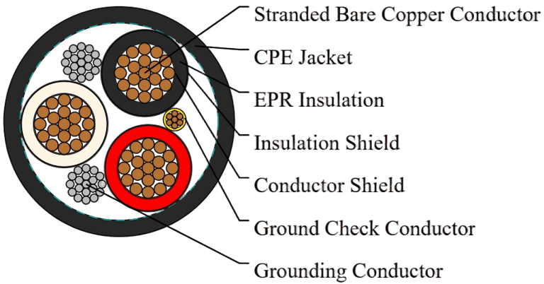
The MP-GC three-conductor mine power feeder cable represents a critical component in modern mining power distribution infrastructure. Engineered specifically for demanding underground and surface mining operations, this 8kV rated cable delivers reliable power transmission between units of mine distribution systems. With its chlorinated polyethylene (CPE) jacket, ethylene propylene rubber (EPR) insulation, and compliance with NEMA WC 58 and ICEA S-75-381 standards, the MP-GC cable provides the durability and safety required in challenging mining environments. Operating continuously at 90°C, this cable offers exceptional performance in wet and dry locations, whether installed in duct, conduit, open air, or direct burial applications.
What is the MP-GC Mine Power Feeder Cable?
The MP-GC designation identifies a specialized three-conductor mine power cable designed for robust power distribution in mining operations. The "MP" classification indicates Mine Power certification, while "GC" denotes the inclusion of a ground check conductor—a critical safety feature that enables continuous monitoring of grounding system integrity. This cable serves as the backbone for distributing electrical power from mine substations to various operational units, supporting both mobile and stationary equipment throughout the facility.
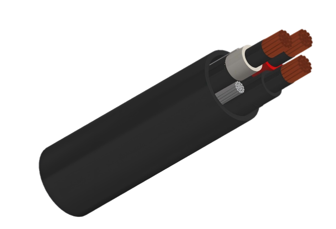
The three-conductor configuration consolidates power delivery into a single cable assembly, simplifying installation and reducing system complexity. Each conductor carries a phase of three-phase power, with additional ground check and grounding conductors providing comprehensive safety protection. This design proves particularly valuable in mining environments where space constraints, harsh conditions, and safety regulations demand efficient, reliable solutions.
Typical Applications in Mining Operations
MP-GC mine power feeder cables excel in numerous mining applications. They form the primary distribution backbone connecting main substations to sectional distribution panels throughout underground mine workings. These cables power continuous miners, shuttle cars, roof bolters, and conveyor systems that form the operational heart of mining operations. Surface applications include connections between processing facilities, maintenance shops, and material handling equipment.
The cable's versatility extends to wet underground environments where water infiltration presents constant challenges. Direct burial installations benefit from the CPE jacket's moisture resistance, while open air installations in mine drifts leverage the cable's flexibility and durability. Unit-to-unit power distribution across varying distances demonstrates the cable's adaptability to diverse mining layouts and operational requirements.
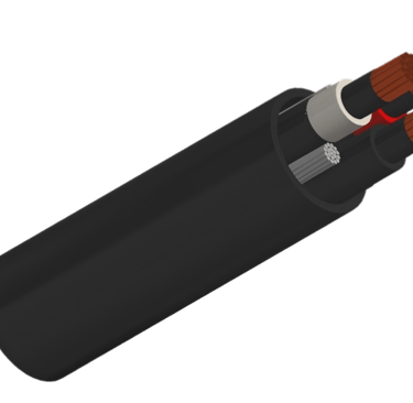


MP-GC Cable Construction: Materials & Design
Conductor System
The foundation of MP-GC cable performance lies in its stranded annealed bare copper conductors. Unlike solid conductors, stranded construction provides superior flexibility, enabling easier routing through tight spaces and around obstacles common in mining installations. Annealing softens the copper, further enhancing flexibility while maintaining excellent electrical conductivity. This stranded design also improves resistance to vibration-induced fatigue, a critical consideration in mining environments where equipment movement and ground settling occur regularly.
The bare copper specification ensures maximum conductivity without the impedance that coating materials might introduce. Stranding also provides redundancy—if individual strands break due to mechanical stress, the remaining strands continue carrying current while the cable maintains structural integrity.
Insulation Layer: Ethylene Propylene Rubber (EPR)
Ethylene propylene rubber insulation delivers exceptional dielectric strength and thermal performance. EPR maintains its electrical properties across a wide temperature range, from -40°C to +90°C continuous operation, with short-circuit capability up to +250°C. This temperature resilience proves essential in mining environments where ambient temperatures vary significantly and equipment loads fluctuate throughout operational cycles.
EPR's inherent moisture resistance prevents insulation degradation in wet locations, a persistent challenge in underground mining. The material's excellent resistance to oils, solvents, and other chemicals encountered in mining operations ensures long-term reliability. Unlike PVC insulation, EPR does not become brittle at low temperatures, maintaining flexibility and mechanical integrity even during cold weather surface installations or in refrigerated mine sections.
Shielding System
The MP-GC cable employs a dual-layer shielding system critical for high-voltage performance. The inner conducting layer, positioned directly over the insulation, provides a smooth, uniform surface that eliminates voids where electrical stress might concentrate. This semiconducting shield maintains intimate contact with the insulation, preventing partial discharge that could degrade insulation over time.
The outer copper tape insulation shield serves multiple purposes: electromagnetic interference (EMI) reduction, voltage stress relief, and fault current return path. When properly grounded, this shield confines the electrical field within the cable, preventing electromagnetic coupling with adjacent cables or equipment. During ground faults, the shield provides a low-impedance path for fault current, facilitating rapid protective device operation.
Ground Check Conductor
The ground check conductor distinguishes MP-GC cables from standard industrial power cables. This copper conductor, insulated with distinctive yellow polypropylene, integrates with mine ground-check monitoring systems that continuously verify grounding system integrity. The system passes low-level current through the ground check conductor, monitoring for interruptions that might indicate damaged grounding conductors or connections.
This proactive safety feature enables detection of grounding problems before they create hazardous conditions. When the monitoring system detects ground check circuit interruption, it alerts operators and may automatically de-energize affected circuits, preventing shock hazards and equipment damage.
Grounding Conductor
Separate from the ground check conductor, the grounding conductor provides the primary fault current return path. Tinned copper construction offers superior corrosion resistance compared to bare copper, critical in wet mine environments where moisture promotes oxidation. The tinned surface maintains low contact resistance at connection points over years of service, ensuring reliable safety grounding throughout the cable's operational life.
Proper sizing of the grounding conductor according to ICEA S-75-381 standards ensures adequate capacity to carry fault currents without excessive temperature rise. This sizing typically relates to the phase conductor size, maintaining appropriate current-carrying balance.
CPE Jacket: Chlorinated Polyethylene
The chlorinated polyethylene jacket provides the cable's first line of defense against environmental hazards. CPE exhibits excellent flame resistance, meeting FT1 and FT2 flame test requirements that limit fire propagation along cable routes. This characteristic proves vital in confined mine spaces where fire represents a catastrophic risk to personnel and operations.
Chemical resistance represents another critical CPE advantage. Mining operations involve exposure to hydraulic fluids, lubricating oils, diesel fuel, and various cleaning solvents. CPE maintains integrity when exposed to these substances, preventing jacket degradation that could compromise underlying cable components. The material's resistance to acids and alkalis further protects against chemical attack from groundwater or process materials.
Temperature stability from -20°C to +105°C accommodates extreme environmental conditions. CPE retains flexibility at low temperatures while resisting softening at elevated temperatures, maintaining mechanical protection across the entire operating range. UV and ozone resistance support surface installations where sunlight exposure occurs, preventing premature jacket deterioration.
Alternative Jacket Options
While CPE represents the standard jacket material, alternative options address specific application requirements. Chlorosulfonated polyethylene (CSP) and polychloroprene (PCP) offer similar but distinct property profiles. Nitrile butadiene rubber (NBR) provides exceptional oil resistance for applications involving heavy petroleum product exposure. Polyvinyl chloride (PVC) and thermoplastic polyurethane (TPU) serve specialized requirements where their specific properties offer advantages over CPE.
MP-GC Cable Technical Specifications & Performance Standards
Voltage & Electrical Characteristics
The 8,000-volt (8kV) rating defines the maximum continuous voltage the cable safely withstands during normal operation. ICEA S-75-381 specifies both 100% and 133% insulation levels, referring to the relationship between rated voltage and insulation withstand capability. The 100% insulation level provides standard protection, while 133% insulation offers enhanced safety margin for critical applications or systems where rapid fault clearing may not occur.
Dielectric strength testing validates insulation performance under stress. New cables undergo AC voltage withstand testing at levels significantly exceeding operating voltage, verifying insulation integrity before deployment. Field testing after installation and during service confirms ongoing insulation health, detecting degradation before failure occurs.
Mechanical Properties
The minimum bending radius of 12 times the cable's outer diameter (12×OD) prevents insulation and conductor damage during installation. For example, a cable with 2-inch outer diameter requires a minimum 24-inch bend radius. Tighter bends risk insulation cracking, conductor strand breakage, and shield disruption. Installation crews must respect this limitation when routing cables around obstacles or through conduit bends.
Tensile strength specifications govern pulling tension during installation. Exceeding maximum pulling tension damages conductors and insulation. Cable manufacturers provide pulling tension limits based on conductor size, and installers use these values to determine appropriate pulling equipment and techniques. Elongation at break measurements indicate the material's ability to withstand stretching before failure, providing safety margins during handling.
Thermal Properties
Maximum continuous operating temperature of +90°C defines normal load-carrying capability. This rating assumes proper installation conditions, including adequate ventilation and thermal dissipation. Ambient temperature significantly impacts current-carrying capacity—higher ambient temperatures reduce the temperature differential available for heat dissipation, requiring current derating to prevent exceeding the +90°C conductor limit.
When multiple cables install in close proximity, mutual heating reduces individual cable ampacity. Derating factors account for this thermal interaction, preventing overheating in bundled cable installations. Underground installations typically encounter stable, moderate ambient temperatures, while surface installations may experience extreme temperature variations requiring more conservative ampacity calculations.
Electrical Performance
Ampacity ratings vary substantially based on installation method. Direct burial installations provide excellent heat dissipation through soil contact, supporting higher current capacity than duct or conduit installations where air gaps limit heat transfer. Installation standards provide detailed ampacity tables accounting for these variations, conductor size, insulation type, and ambient conditions.
Insulation resistance measurements verify insulation health. High insulation resistance (typically hundreds of megohms) indicates sound insulation, while declining values suggest moisture ingress or insulation degradation. Regular insulation resistance testing during maintenance intervals detects developing problems before service disruption occurs.
Capacitance and inductance characteristics affect voltage drop and system power factor, particularly in longer cable runs. These parameters factor into system design calculations, ensuring voltage at load terminals remains within acceptable limits.
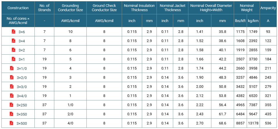
Standards & Regulatory Compliance
ICEA S-75-381 & NEMA WC 58
The Insulated Cable Engineers Association (ICEA) S-75-381 standard and National Electrical Manufacturers Association (NEMA) WC 58 specification establish comprehensive requirements for mine power feeder cables. These standards define construction details, materials specifications, testing procedures, and performance criteria ensuring cables meet industry safety and reliability expectations.
The distinction between 100% and 133% insulation levels addresses different system grounding approaches and fault clearing capabilities. Systems with rapid fault detection and clearing may use 100% insulation level cables, while systems with slower protection or ungrounded operation benefit from 133% insulation's additional safety margin.
ASTM B-8 Specifications
American Society for Testing and Materials (ASTM) B-8 specifications govern copper conductor strand requirements. This standard defines minimum tensile strength, elongation percentages, and conductivity levels ensuring conductors provide reliable electrical performance and mechanical durability. Compliance with ASTM B-8 guarantees conductor quality from reputable manufacturers.
CAN/CSA C22.2 No. 96
Canadian Standards Association (CSA) certification under CAN/CSA C22.2 No. 96 enables legal installation in Canadian mining operations. This standard imposes rigorous safety requirements addressing unique aspects of Canadian mining regulations. CSA certification involves comprehensive testing and factory audits, providing assurance of consistent quality and regulatory compliance.
MSHA Compliance
The Mine Safety and Health Administration (MSHA) establishes U.S. mining safety regulations, including electrical system requirements. MP-GC cables meet MSHA flame-resistant specifications, limiting fire hazards in underground mines. MSHA regulations govern installation practices, maintenance procedures, and testing requirements, ensuring safe electrical systems throughout mine operations.
Installation Guidelines for MP-GC Mine Power Feeder Cable
Installation Methods
Duct installation provides mechanical protection and facilitates cable replacement. Cables pull through buried or embedded ducts using appropriate pulling equipment and lubricants to minimize friction. Duct sizing must accommodate cable diameter with sufficient clearance for installation while maintaining acceptable conduit fill percentages for heat dissipation.
Conduit installation offers superior mechanical protection, ideal for areas with heavy traffic or equipment operation. Rigid metal conduit or intermediate metal conduit provides excellent cable protection, though installation costs exceed duct or direct burial methods. Conduit bends must maintain minimum radius requirements, using long-radius fittings where necessary.
Open air installation in mine drifts or surface rack systems allows maximum heat dissipation and easy inspection. Cables require support at regular intervals using appropriate clamps or cable trays. Support spacing considers cable weight, preventing excessive sag that might stress conductors or connections. Mechanical protection may be necessary in areas where physical damage risk exists.
Direct burial installation eliminates conduit costs while providing good heat dissipation. Burial depth must meet MSHA and local code requirements, typically 24-36 inches, protecting cables from surface damage. Backfill material should be rock-free to prevent jacket damage, and warning tape above the cable alerts future excavators to buried cables.
Common Cable Problems and Solutions
Problem: Premature Insulation Failure
Insulation failures often result from moisture ingress through damaged jackets or terminations. Prevention requires careful handling during installation, avoiding sharp bends or pulls exceeding tension limits. Regular visual inspections identify jacket damage before moisture penetrates insulation. Proper termination techniques, including heat-shrink stress relief boots and moisture sealing, prevent water entry at vulnerable cable ends.
Problem: Ground Check Circuit Failures
Ground check conductor interruptions typically occur at termination points or where mechanical stress concentrates. Solution involves meticulous termination practices, ensuring secure connections with appropriate hardware. Strain relief at terminations prevents conductor fatigue from cable movement. When troubleshooting ground check failures, systematically test circuit sections to isolate damaged segments.
Problem: Overheating and Capacity Exceedance
Cables operating above rated capacity overheat, accelerating insulation aging and potentially causing failure. This problem stems from undersized cable selection or changed load conditions. Solution requires load current verification against ampacity tables, considering installation method and ambient temperature. When loads exceed cable capacity, options include load reduction, installation method modification for improved cooling, or cable replacement with larger conductors.
Problem: Physical Damage from Mining Operations
Mechanical damage from equipment contact, rock falls, or ground movement causes jacket punctures and conductor damage. Prevention emphasizes proper cable routing away from high-traffic areas, adequate mechanical protection in vulnerable locations, and secure mounting preventing cable movement. Regular inspections identify developing damage, enabling repairs before serious failure occurs.
Problem: Connection Point Failures
Terminations and splices represent frequent failure points due to improper installation or environmental exposure. High-quality connectors appropriate for mining service, proper crimping or compression techniques, and environmental sealing prevent most connection failures. Training installation personnel in correct termination procedures and using manufacturer-approved materials ensures reliable connections.
Key Advantages of MP-GC Mine Power Feeder Cable
The MP-GC mine power feeder cable with CPE jacket delivers proven reliability in the harshest mining environments. Its comprehensive safety features, including dedicated ground check conductor and robust shielding system, protect personnel and equipment. The cable's durability ensures extended service life, minimizing replacement costs and operational disruptions.
Installation versatility accommodates diverse mining layouts and operational requirements. Whether installed in duct, conduit, open air, or direct burial, the cable maintains performance standards. Compliance with NEMA WC 58, ICEA S-75-381, ASTM B-8, and CAN/CSA C22.2 No. 96 standards provides regulatory confidence and insurance approval.
The combination of EPR insulation and CPE jacket delivers exceptional environmental resistance. Performance in wet and dry locations, chemical resistance, and flame retardant properties address the multiple hazards present in mining operations. The 90°C continuous operating temperature supports modern high-capacity mining equipment demands.
Conclusion: MP-GC Mine Power Feeder Cable Excellence
The Type MP-GC three-conductor mine power feeder cable represents the industry standard for reliable, safe power distribution in mining applications. Its engineered construction, incorporating stranded copper conductors, EPR insulation, comprehensive shielding, ground check capability, and CPE jacket protection, addresses the unique challenges of mining electrical systems. Compliance with rigorous industry standards ensures consistent quality and regulatory acceptance.
Whether powering underground mining operations or surface facilities, the MP-GC cable delivers the performance, safety, and durability mining operations demand. Its versatility across installation methods and environmental conditions makes it the preferred choice for mine electrical engineers and contractors. For technical assistance, detailed specifications, or custom cable configurations, contact qualified mining cable suppliers who can provide expert guidance tailored to specific application requirements.
How to Reach Us
Get in Touch
SiteMap
Product Catalogue
Festoon Cable
Shore Power Cable




Scan to add us on WeChat