
(N)TMCGCW11Y Medium Voltage Cable Selection Guide for Electric Rope Shovels and Crane Applications
A practical step-by-step selection guide for (N)TMCGCW11Y medium voltage cables in electric rope shovels and crane applications. Covers rated voltage classes, bending radius, tensile load, movement speed, and the most common specification mistakes made by crane manufacturers and project engineers.
hongjing.Wang@Feichun
3/13/20267 min read
Introduction
Selecting the wrong medium voltage cable for an electric rope shovel or port crane is not a minor oversight — it can mean unplanned downtime, premature cable failure, safety incidents, and costly mid-project replacements. Real-world deployments in demanding mining and port environments, such as electric rope shovels at large open-cut copper mines like Olympic Dam in South Australia, have validated that cable selection for high-flex, medium voltage applications demands a systematic, parameter-driven approach.
This guide walks project engineers and crane manufacturers through a structured cable selection process for (N)TMCGCW11Y-type screened single-core medium voltage cables — the class of cable most commonly specified for these demanding applications.
Step-by-Step Cable Selection Method
Step 1 — Define the Application Type
Before looking at any technical datasheet, classify the exact duty of the cable installation. The two primary modes are fundamentally different:
Fixed Installation The cable is stationary once laid. Thermal and electrical parameters drive selection. Mechanical dynamic ratings are secondary.
Flexible / Moving Installation The cable is subject to repeated movement — energy chains, reeling drums, festoon systems, or cable carriers. This is the dominant mode for electric rope shovels and port/intermodal cranes. Dynamic mechanical parameters become the primary selection criteria.
For Shore Power Systems feeding container vessels, cable movement is relatively slow (typically around 6 m/min). For energy chains on port cranes, speeds can reach 70 to 240 m/min. These are not interchangeable duty categories, and a cable rated for one must be verified for the other.
Step 2 — Establish the Rated Voltage and Voltage Class
Medium voltage cable standards define rated voltage as U₀/U, where U₀ is the voltage between conductor and earth, and U is the voltage between conductors. Selecting the wrong voltage class is one of the most common and consequential mistakes in cable procurement.
For (N)TMCGCW11Y cables, the available rated voltage classes are:
3.6/6 kV
6/10 kV
8.7/15 kV
12/20 kV
14/25 kV
18/30 kV
Each class carries a corresponding maximum permissible AC operating voltage and DC operating voltage, as well as a defined AC test voltage per DIN VDE 0250-813. Always verify:
The actual system operating voltage under normal and contingency conditions
Whether the cable will be used in an AC or DC system, as maximum permissible operating voltages differ between these
Any overvoltage events that could transiently exceed the rated class
For electric rope shovel trailing cable applications at mine sites, the 6/10 kV or 8.7/15 kV classes are typically specified depending on the site distribution voltage. Never select based on rated voltage alone — always confirm the maximum permissible operating voltage for both AC and DC configurations applicable to your system.
Step 3 — Determine the Required Cross-Section Based on Current Carrying Capacity
Current carrying capacity is determined according to IEC 60364-5-52 at a conductor operating temperature of 90°C and a reference ambient temperature of 30°C, using installation method F (free in air) with three loaded conductors in trefoil configuration.
Key inputs for this calculation:
Full load current of the connected equipment (shovel drive, hoist motor, etc.)
Ambient temperature at installation — underground environments and tropical surface sites differ significantly from the 30°C reference
De-rating factors per DIN VDE 0298-4 must be applied where conditions deviate from the reference
For single-core screened cables of this type, available cross-sections typically range from 1×25/16 mm² up to 1×300/25 mm², where the second number represents the concentric ground conductor cross-section. At the upper end of the range, some cross-sections may fall outside UL-approved ranges — confirm certification requirements early in the project, particularly for equipment destined for North American markets.
Step 4 — Verify the Bending Radius Against the Installation Geometry
This is the parameter most frequently underestimated in machine cable applications.
For (N)TMCGCW11Y cables:
Fixed installation minimum bending radius: 6 × outer cable diameter
Free-moving / dynamic installation minimum bending radius: 8 × outer cable diameter
The outer diameter of the cable varies with cross-section and voltage class. For example, at 6/10 kV:
A 1×25/16 mm² cable has an outer diameter in the range of 21–23 mm, giving a minimum dynamic bending radius of approximately 168–184 mm
A 1×240/25 mm² cable has an outer diameter of 36–38 mm, requiring a minimum dynamic bending radius of approximately 288–304 mm
When specifying cable carrier systems, festoons, or reeling drums, the mechanical designer must confirm that the minimum bend radius in the system geometry at any point in the travel path is always larger than the cable's minimum permissible value. Apply a design margin — do not design to the minimum limit.
Step 5 — Check Tensile Load Capacity
The maximum tensile load for cables in this class is 15 N/mm² applied to the conductor cross-section.
For a 1×95/16 mm² cable: maximum tensile load = 95 mm² × 15 N/mm² = 1,425 N
This figure represents the permissible load in normal operation. For reeling and energy chain systems, transient peak loads during acceleration, emergency stops, or cable snag events must be analysed. Verify that peak dynamic loads remain within the permissible limit with appropriate safety margins.
Tensile load calculations should also account for the weight of the suspended cable length in vertical or near-vertical runs — a parameter often overlooked when the focus is on horizontal energy chain travel.
Step 6 — Confirm Environmental and Chemical Compatibility
Cables in this class are designed for demanding environments, but confirming compatibility against the actual installation conditions remains the engineer's responsibility.
Temperature range:
Fixed installation: –50°C to +90°C ambient
Flexible operation: –40°C to +90°C ambient
Note that the lower limit for flexible operation is less extreme than for fixed installation. In cold-climate mine sites, if cables must flex at temperatures below –40°C, additional evaluation is required.
Chemical and environmental resistance:
Oil resistance per DIN EN / IEC 60811-404 — relevant for equipment near hydraulic systems and lubricated mechanical components
Flame retardant per EN 60332-1-2 — important for underground and enclosed spaces
Halogen-free sheath (EN 60754) — required in many underground mining safety codes
UV resistance — essential for open-cut mine and port outdoor applications
Ozone resistance — relevant in coastal port environments
Water immersion:
This cable type can be permanently submerged at pressures up to 10 bar, corresponding to protection class Ad8. This is relevant for offshore and port applications where cable trays may flood.
Step 7 — Verify the Outer Sheath Material and Colour Coding
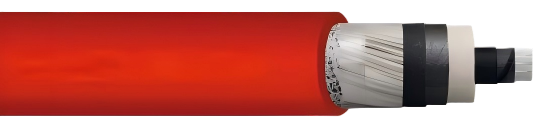
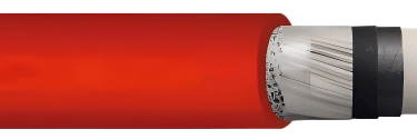
The thermoplastic polyether-based polyurethane (TPU) outer sheath provides the combination of mechanical robustness, flexibility at low temperature, oil resistance, and halogen-free fire behaviour required in these applications. The standard sheath colour is red with inkjet marking.
Confirm that the sheath colour and marking convention are compatible with site cable management and identification requirements. Some mining sites mandate specific colour-coding schemes for medium voltage cables.
Step 8 — Confirm Certifications and Standards Compliance
For global projects, certification requirements vary by region and by end-use application:
UL Listing (North American market): confirm the selected cross-section falls within the UL-approved range
RoHS 2015/863/EU: compliance with EU hazardous substances restrictions
CPR 305/2011: EU Construction Products Regulation classification
DIN VDE 0250-813: the governing German/European design standard for this cable type
Certificates should be verified against the specific catalogue number, not assumed from the cable type designation alone.
Key Parameters Summary
Voltage
Always specify U₀/U rated voltage, not just nominal system voltage. Confirm maximum permissible operating voltages for both AC and DC configurations. Verify the AC test voltage the cable was subjected to in factory acceptance testing.
Bending Radius
The dynamic bending radius (≥ 8 × outer Ø for free-moving installations) governs cable carrier and drum design. It varies with cable outer diameter, which in turn varies with cross-section and voltage class. Calculate the actual minimum radius for every cross-section you specify.
Tensile Load
Maximum 15 N/mm² on conductor cross-section. Account for cable self-weight in vertical runs and dynamic peak loads from acceleration and emergency stops. Apply a design margin to avoid operating at the permissible limit.
Movement Speed
Shore power and slow-reeling systems operate at approximately 6 m/min. High-speed energy chain applications on port cranes can reach 70–240 m/min. Ensure the cable type and configuration are validated for the actual speed class.
Ambient Temperature
The –40°C lower limit for flexible operation is a hard constraint. Cold climate sites must verify that temperatures during operation do not fall below this threshold when flexibility is required.
Common Cable Selection Mistakes
Specifying rated voltage from the system line voltage alone U and U₀ are different values. A 10 kV system (line-to-line) requires a cable with U = 10 kV minimum, which means selecting the 6/10 kV class — but the 8.7/15 kV class may be more appropriate once maximum operating voltage contingencies are considered.
Using fixed-installation bending radius for moving cable applications The difference between 6× and 8× outer diameter is significant in tight cable carrier designs. Using the fixed-installation figure in a dynamic application will cause premature conductor and insulation fatigue.
Ignoring the de-rating factors Current carrying capacity tables are published for 30°C ambient in free air. Mining environments — particularly near drive motors, inside cable ducts, or in tropical surface conditions — may require substantial de-rating. Failing to apply DIN VDE 0298-4 de-rating factors leads to overloaded cables.
Selecting cross-section based on current capacity without checking tensile load In long trailing cable or vertical riser applications, a cross-section adequate for current may be mechanically undersized for tensile load. Both constraints must be checked independently.
Assuming a cable certified at one cross-section is certified at all cross-sections UL approval ranges are specific. Always verify that the exact cross-section you are procuring falls within the approved range, not just the cable type.
Specifying halogenated-sheath cable for underground or enclosed applications Many mine sites and port terminal facilities mandate halogen-free cable in enclosed areas due to toxic gas generation in fire conditions. Substituting a standard PVC-sheathed cable for a halogen-free TPU type without reviewing site safety requirements is a common procurement error.
Overlooking the protective conductor cross-section The designation 1×95/16 mm² means 95 mm² main conductor and 16 mm² concentric ground conductor. Some engineers focus solely on the main conductor current capacity without verifying that the ground conductor is adequate for the fault current clearing time and magnitude at the installation.
Final Notes for Project Engineers
Cable selection for electric rope shovels and high-flex crane applications is a multi-parameter engineering exercise, not a catalogue lookup. Voltage class, current capacity, bending radius, tensile load, movement speed, and environmental conditions must all be evaluated simultaneously against the specific installation geometry and operating duty.
Document your selection rationale — including all de-rating factors applied and the basis for the minimum bending radius in the cable carrier design — in the project cable schedule. This record is essential for maintenance teams who will inspect and replace cables during the equipment service life, and for any future investigation into premature cable failures.
Manufacturers retain the right to modify cable specifications. Always obtain the current revision of the technical datasheet at the time of procurement, and verify that the catalogue number in your bill of materials corresponds to the specification on which your selection was based.
This guide is intended as a practical reference for qualified electrical engineers and crane manufacturers. All selections must be verified against current standards, manufacturer datasheets, and site-specific conditions by a competent engineer.
How to Reach Us
Get in Touch
SiteMap
Product Catalogue
Festoon Cable
Shore Power Cable




Scan to add us on WeChat