
OPTOFLEX Fiber Optic Cable: Complete Technical Guide for Crane and Material Handling Applications
Discover OPTOFLEX G62.5/125, G50/125, E9/125 fiber optic rubber cables for cranes and material handling equipment. Flexible, durable cables with high data rates, large bandwidth, and absolute electromagnetic immunity. Suitable for reels, festoon systems, and cable tenders. Technical specifications, applications, and performance data included.
hongjing.Wang@Feichun
12/4/202512 min read

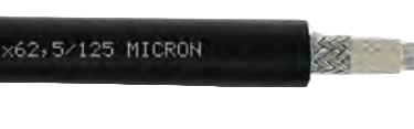
Introduction to OPTOFLEX Fiber Optic Technology
In modern industrial environments where electromagnetic interference poses significant challenges to data transmission, fiber optic cables have emerged as the definitive solution for reliable signal communication. The OPTOFLEX fiber optic cable represents a specialized engineering achievement designed specifically for crane and material handling equipment operating under demanding mechanical conditions.
Unlike traditional copper-based data transmission systems, fiber optic technology transmits information using light pulses through glass fibers, providing absolute immunity to electromagnetic interference. This fundamental advantage makes fiber optic cables particularly valuable in industrial settings where heavy electrical equipment, variable frequency drives, and high-voltage power systems create challenging electromagnetic environments.
The OPTOFLEX cable series encompasses three distinct fiber type variants—G62.5/125, G50/125, and E9/125—each engineered to meet specific bandwidth and distance requirements. These configurations enable system designers to select the optimal solution based on transmission distance, data rate requirements, and installation conditions.
Primary Applications in Industrial Environments
Crane and Material Handling Equipment
Fiber optic cables for cranes serve critical functions in modern material handling operations. Container terminals, port facilities, and manufacturing plants rely on OPTOFLEX cables to transmit control signals, safety data, and operational information between mobile crane components and fixed control systems. The cable's flexibility and durability enable reliable performance across gantry movements, trolley operations, and various cable guidance systems.
In tower crane applications, the cable provides uninterrupted data transmission despite constant movement, vibration, and exposure to outdoor environmental conditions. The robust rubber sheath construction protects the delicate optical fibers while maintaining the flexibility necessary for dynamic installations.
Cable Handling Systems Compatibility
OPTOFLEX cables demonstrate exceptional compatibility with multiple cable handling systems commonly employed in material handling equipment:
Reeling Systems: When installed on cylindrical reels, the cable maintains signal integrity throughout continuous winding and unwinding cycles. The recommended minimum bending radius of 250mm for reeling operations ensures long-term reliability without compromising the optical fibers.
Festoon Systems: Cable tenders and festoon carriers benefit from the cable's lighter weight compared to equivalent copper conductor systems. The 125mm minimum bending radius for festoon applications allows compact installation configurations while preserving transmission characteristics.
Cable Tenders: The combination of mechanical flexibility and torsional stability makes OPTOFLEX suitable for cable tender systems where the cable experiences multi-directional movement and varying tension loads.
High Data Rate Transmission Requirements
Modern automation systems demand increasingly higher data transmission rates. The OPTOFLEX cable series addresses these requirements through carefully selected fiber types and optimized bandwidth characteristics. Industrial Ethernet protocols, real-time control systems, and video monitoring applications all benefit from the large bandwidth capacity inherent in fiber optic technology.
Technical Specifications and Design Features
Optical Fiber Core Configurations
The OPTOFLEX cable accommodates three primary fiber types, each suited to specific application requirements:
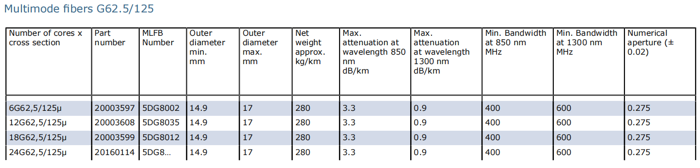
G62.5/125 Multimode Fiber: This graded-index fiber features a 62.5 μm core diameter and provides cost-effective performance for standard industrial applications. Maximum attenuation measures 3.3 dB/km at 850 nm and 0.9 dB/km at 1300 nm wavelengths. The minimum bandwidth of 400 MHz at 850 nm and 600 MHz at 1300 nm supports transmission distances typically up to 2 kilometers, making it suitable for most crane and material handling installations. The numerical aperture of 0.275 ± 0.02 facilitates easier coupling and termination procedures.
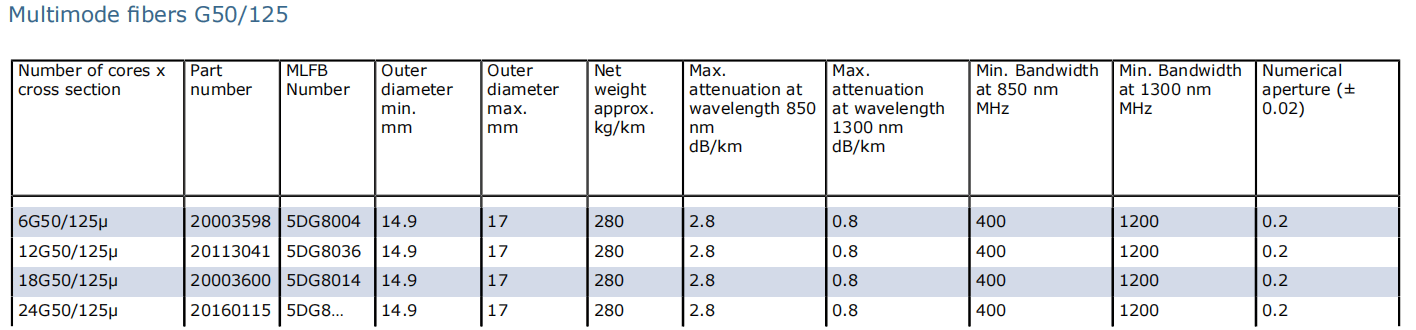
G50/125 Graded-Index Fiber: With a reduced core diameter of 50 μm, this fiber type offers enhanced performance characteristics. Maximum attenuation improves to 2.8 dB/km at 850 nm and 0.8 dB/km at 1300 nm. The significantly higher minimum bandwidth of 1200 MHz at 1300 nm enables extended transmission distances of 3-5 kilometers with superior data integrity. The tighter numerical aperture of 0.2 ± 0.02 provides better modal distribution for improved long-distance performance.
E9/125 Singlemode Fiber: For applications requiring maximum transmission distance and bandwidth, the 9 μm core singlemode fiber delivers exceptional performance. Maximum attenuation of 0.4 dB/km at 1300 nm and 0.3 dB/km at 1550 nm enables transmission distances exceeding 40 kilometers. Chromatic dispersion specifications of 3.5 ps/nm·km at both 1300 nm and 1550 nm wavelengths ensure minimal signal degradation over extended distances. This fiber type serves advanced automation systems and future-proof installations.
Cable Construction and Mechanical Design
The OPTOFLEX cable employs a sophisticated multi-layer construction optimized for mechanical durability while protecting the sensitive optical fibers:
Fiber Protection System: Each individual fiber receives a dual-layer coating system. The primary 125 μm cladding surrounds the core, followed by a protective 250 μm coating layer. This coating absorbs mechanical stresses and prevents micro-bending losses during cable flexing.
Hollow Core with Filling Compound: Six fibers are arranged in hollow cores constructed from ETFE (Ethylene Tetrafluoroethylene) with a specialized 7YI1 filling compound. This compound provides moisture protection while allowing the fibers to move slightly within the core, reducing stress concentration during bending.
Central Support Element: A glass-fiber reinforced plastic (GFK) support element occupies the cable center, providing tensile strength and maintaining cable geometry under mechanical stress. This design enables the cable to withstand up to 500 N maximum tensile load without transferring stress to the optical fibers.
Core Arrangement: The six fiber-containing cores are laid up in a single layer around the central GFK support element. This arrangement ensures uniform mechanical stress distribution and maintains consistent bending characteristics throughout the cable length.
Inner Sheath Protection: A special compound inner sheath encapsulates the core assembly, providing additional mechanical protection and maintaining the position of individual elements during flexing cycles.
Reinforcement Layer: A polyester braid with approximately 80% surface coverage is embedded between the inner and outer sheaths. This reinforcement enhances tear resistance and distributes tensile forces across the cable structure.
Outer Sheath: The black PCP rubber compound (5GM3 type) outer sheath delivers exceptional resistance to abrasion, tearing, ozone, ultraviolet radiation, and oil exposure. This final protective layer ensures reliable performance in harsh industrial environments.
Available Configurations and Dimensions
OPTOFLEX cables are manufactured in multiple core configurations to accommodate varying system requirements:
6 fiber elements: Suitable for basic control and monitoring applications
12 fiber elements: Provides capacity for redundant systems or multiple communication channels
18 fiber elements: Supports complex automation systems with multiple subsystems
24 fiber elements: Enables comprehensive data networks with extensive monitoring capabilities
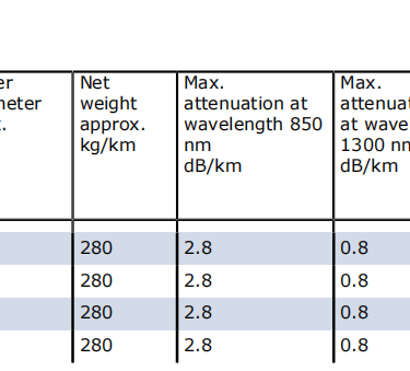
Standard outer diameter ranges from 14.9 mm minimum to 17 mm maximum, regardless of fiber count. This consistent geometry simplifies cable management system design and component selection. The approximate net weight of 280 kg/km facilitates handling and installation planning.
Performance Characteristics and Transmission Data
Multimode Fiber Performance Specifications
G62.5/125 Operational Parameters: This multimode configuration achieves maximum attenuation of 3.3 dB/km at 850 nm wavelength, suitable for LED-based transmission systems. At 1300 nm wavelength, attenuation reduces to 0.9 dB/km maximum, enabling longer link distances. The minimum bandwidth of 400 MHz at 850 nm and 600 MHz at 1300 nm supports data rates appropriate for industrial control protocols and standard Ethernet implementations.
G50/125 Enhanced Performance: The graded-index 50 μm core fiber demonstrates superior characteristics with 2.8 dB/km maximum attenuation at 850 nm and 0.8 dB/km at 1300 nm. The exceptional 1200 MHz minimum bandwidth at 1300 nm wavelength accommodates higher data rates and longer transmission distances, making this fiber type ideal for extended gantry crane systems and large port installations.
Singlemode Fiber Long-Distance Capabilities
The E9/125 singlemode configuration provides the highest performance specifications in the OPTOFLEX series. Maximum attenuation of 0.4 dB/km at 1300 nm and 0.3 dB/km at 1550 nm enables transmission spans exceeding 40 kilometers without signal regeneration. The numerical aperture of 0.14 ± 0.02 and chromatic dispersion specifications of 3.5 ps/nm·km ensure excellent signal quality for high-bandwidth, long-distance applications.
Environmental and Chemical Resistance
Oil Resistance Standards Compliance
The OPTOFLEX cable meets stringent oil resistance requirements according to DIN EN 60811-404 and DIN VDE 0473-811-404, paragraph 10. This compliance ensures reliable operation in industrial environments where hydraulic fluids, lubricating oils, and petroleum-based substances may contact the cable surface. The specialized rubber compounds resist degradation, swelling, and loss of mechanical properties when exposed to these chemicals.
Weather Resistance for Outdoor Installation
Unrestricted outdoor and indoor use characterizes the OPTOFLEX cable's environmental capability. The PCP rubber outer sheath demonstrates excellent resistance to ozone exposure, which commonly degrades inferior rubber compounds in outdoor applications. Ultraviolet radiation resistance prevents surface cracking and compound deterioration during extended sun exposure.
Moisture Protection Design
The water-resistant construction prevents moisture penetration into the fiber-containing cores. The filling compounds within the hollow cores create a moisture barrier, while the multiple sheath layers provide redundant protection. This design maintains signal integrity in wet environments, including marine applications and outdoor installations exposed to rain, humidity, and condensation.
Mechanical Performance and Durability
Tensile Load Capacity
The OPTOFLEX cable withstands a maximum tensile load of 500 N, a specification achieved through the integration of the central GFK support element. This tensile strength exceeds typical operational loads encountered in crane and festoon systems, providing a safety margin that extends cable service life. Unlike copper conductor cables where tensile stress directly impacts the current-carrying conductors, the fiber optic design protects the signal-transmitting elements from mechanical stress.
Torsional Stress Tolerance
Cable installations frequently experience torsional stress during operation, particularly at entry points, slewing rings, and guidance system misalignments. The OPTOFLEX cable accommodates torsional stress of 50 degrees per meter minimum (±25°/m). This specification applies to gradual torsional loading rather than sudden twisting, which should be avoided through proper installation practices and alignment of cable guidance systems.
Bending Radius Requirements
Proper installation requires adherence to specified minimum bending radii to prevent fiber damage and signal loss:
Fixed Installation: 125 mm minimum bending radius applies to stationary cable sections where the cable route includes curves but experiences no repeated flexing.
Festoon System Operation: The 125 mm minimum bending radius accommodates the dynamic bending experienced in festoon carriers and cable tenders while maintaining fiber integrity throughout millions of motion cycles.
Reeling Operations: A more conservative 250 mm minimum bending radius is specified for cables installed on cylindrical reels. This larger radius accounts for the tighter bend experienced during the innermost wrap layers and the repeated bending cycles inherent in reeling applications.
S-Type Directional Changes: When the cable route includes reverse bends or S-curves, a minimum distance of 20 times the cable diameter (20 × D) must separate the bending points. This specification prevents excessive localized stress that could damage the optical fibers.
Travel Speed Capabilities
Different cable guidance systems impose varying mechanical demands on installed cables:
Gantry Reeling Operation: The OPTOFLEX cable supports gantry crane speeds up to 120 m/min when properly installed on cylindrical or mono-spiral reels. Random-wound reels are not recommended as they can create unpredictable stress patterns. The relatively moderate speed specification for reeling applications reflects the more severe mechanical environment compared to festoon systems.
Trolley Festoon Systems: Installation on festoon carriers or cable tenders enables operation at speeds up to 240 m/min. The lower mechanical stress in properly designed festoon systems allows this higher speed specification. The cable's flexibility and the distributed bending characteristic of festoon systems contribute to reliable high-speed performance.
Hoist Applications: The OPTOFLEX standard configuration is not designed for hoist-type vertical reeling applications where the cable experiences different stress patterns and potentially higher dynamic loads.
Temperature and Thermal Characteristics
Operating Temperature Range
The OPTOFLEX cable maintains reliable performance across a wide ambient temperature range:
Fixed Installation: Temperature limits of -40°C to +80°C accommodate installation in climate-controlled facilities as well as outdoor environments experiencing seasonal temperature extremes. The specialized rubber compounds retain flexibility at low temperatures while maintaining mechanical integrity at elevated temperatures.
Fully Flexible Operation: During dynamic operation involving repeated flexing, the specified ambient temperature range of -35°C to +80°C ensures the cable sheath materials maintain adequate flexibility for millions of bending cycles. The slightly elevated minimum temperature for flexible operation (-35°C versus -40°C) reflects the increased mechanical demands during dynamic use.
These temperature specifications distinguish the OPTOFLEX cable from standard fiber optic cables, which often exhibit reduced flexibility or premature failure when operated at temperature extremes while experiencing mechanical stress.
Standards and Certifications
FDDI Foundation
The OPTOFLEX cable design is based on the Fiber Distributed Data Interface (FDDI) standard, originally developed for high-speed local area networks. This foundation ensures compatibility with established fiber optic transmission protocols and equipment.
International Standards Compliance
ISO/IEC 9314 Part 3: Compliance with this international standard ensures the fiber specifications meet globally recognized performance criteria for graded-index and singlemode optical fibers.
DIN VDE 0888: This German standard for fiber optic cables provides additional specification requirements that ensure the cable's suitability for industrial applications.
The combination of international standards compliance and proven field performance establishes the OPTOFLEX cable as a reliable solution for demanding industrial environments worldwide.
Electromagnetic Interference Immunity
Absolute EMI Protection
Fiber optic data transmission provides complete immunity to electromagnetic interference, a critical advantage in industrial environments. Power cables carrying high currents, variable frequency drives generating harmonic distortion, and electrical equipment producing electromagnetic fields cannot induce noise or signal degradation in fiber optic systems. This inherent immunity eliminates the need for shielding, grounding, and separation requirements that constrain copper-based data systems.
Noise-Free Data Transmission
Industrial facilities often struggle with data transmission reliability when copper cables route near high-power electrical equipment. Motor drives, welding equipment, and switching power supplies generate electromagnetic noise that couples into parallel copper data cables, causing transmission errors and system malfunctions. Fiber optic cables eliminate these concerns entirely, enabling reliable data transmission regardless of proximity to interference sources.
High-Voltage Equipment Proximity
The non-conductive nature of optical fibers provides a safety advantage when data cables must route near high-voltage power systems. Unlike copper cables that can inadvertently conduct fault currents or create hazardous touch voltages, fiber optic cables pose no electrical hazard. This characteristic simplifies installation in complex industrial environments where power and control systems share common routing paths.
Fiber Type Selection and Application Guidance
When to Specify G62.5/125 Multimode Fiber
Standard industrial applications operating over moderate distances represent the ideal application for G62.5 multimode fiber. Cost-effective system design, adequate bandwidth for industrial protocols, and compatibility with existing LED-based transmission equipment make this fiber type suitable for typical crane control systems. The larger core diameter simplifies termination procedures and reduces sensitivity to connector cleanliness, reducing installation and maintenance costs.
G50/125 Graded-Index Application Scenarios
Extended gantry crane systems, large port facilities, and installations requiring higher bandwidth benefit from G50 graded-index fiber. The improved bandwidth and lower attenuation enable reliable transmission over distances of 3-5 kilometers, accommodating the largest material handling installations. Higher data rates support advanced automation systems incorporating video monitoring, real-time position feedback, and complex control algorithms.
E9/125 Singlemode for Maximum Performance
Long-distance transmission requirements, highest bandwidth applications, and future-proof installations justify the specification of E9 singlemode fiber. Although requiring more precise termination procedures and laser-based transmission equipment, singlemode systems provide performance margins that ensure reliable operation as system requirements evolve. Advanced automation systems incorporating artificial intelligence, predictive maintenance algorithms, and comprehensive data logging benefit from singlemode capabilities.
Installation and Operating Guidance
Cable Management Best Practices
Proper installation practices significantly impact system reliability and cable service life. Support spacing should prevent excessive sag that increases tensile stress during operation. Cable routing must avoid sharp edges and rough surfaces that could abrade the outer sheath. Protection from mechanical impact in areas where the cable could be struck by moving equipment or falling objects extends operational life.
Reel System Installation Recommendations
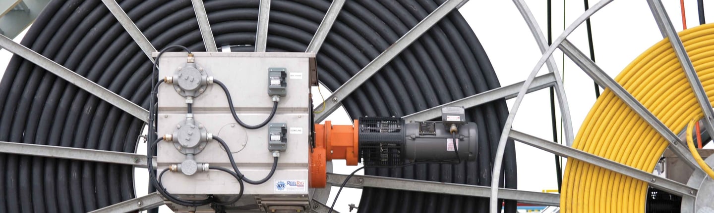
Cylindrical reel installation requires attention to several factors. The cable should be wound onto the reel with consistent tension to prevent loose wraps that could create tangles or tight wraps that overstress the cable. The reel diameter should provide the specified minimum bending radius for all wrap layers, including the innermost wraps where the bending radius is smallest. Mono-spiral reels that maintain constant bending radius throughout the winding cycle provide optimal performance.
Festoon System Configuration
Festoon carriers should be spaced to maintain the cable in a catenary curve without excessive sag. The cable weight and span length determine appropriate carrier spacing. Smooth-running carriers minimize friction and wear on the cable surface. Guidance systems must prevent the cable from rubbing against structural members or other cables in multi-cable installations.
Common Issues and Troubleshooting
Signal Loss Problems
Issue: Gradual increase in signal loss over time, eventually causing transmission errors or complete signal failure.
Diagnosis: Excessive bending below the specified minimum radius can cause micro-bending losses that gradually accumulate. Contamination of fiber end faces at connectors introduces insertion loss that appears as reduced signal strength. Fiber breakage due to mechanical damage creates complete signal loss.
Solution: Verify all bending radii exceed specified minimums, particularly at entry points and guidance system pulleys. Inspect and clean connector end faces using proper fiber optic cleaning procedures. If fiber breakage is suspected, the cable section must be replaced as field splicing is typically not practical in industrial installations.
Intermittent Signal Interruptions
Issue: Unpredictable temporary loss of data transmission that spontaneously recovers.
Diagnosis: Loose connections at termination points can cause intermittent loss. Excessive vibration or shock loading may temporarily disrupt the optical signal. Inadequate strain relief allowing connector movement creates intermittent problems.
Solution: Verify all connectors are properly seated and secured. Ensure termination points include adequate strain relief that prevents force transmission to the fiber connections. In high-vibration environments, consider additional isolation or mounting improvements.
Accelerated Cable Wear
Issue: Premature sheath damage, cracking, or mechanical failure before expected service life.
Diagnosis: Excessive tensile load beyond the 500 N specification overloads the cable structure. Operation outside the specified temperature range degrades the rubber compounds. Exposure to chemicals not compatible with the sheath materials causes premature deterioration. Torsional stress exceeding specifications twists the cable structure.
Solution: Verify actual tensile loads remain within specifications, possibly requiring installation modifications to reduce loading. Ensure ambient temperature remains within specified limits. Investigate chemical exposure and provide additional protection if incompatible substances contact the cable. Review installation for sources of excessive torsional stress and implement design modifications to reduce twisting.
Reduced Flexibility in Cold Conditions
Issue: Cable becomes stiff and difficult to handle when ambient temperature drops, potentially causing operational problems or installation delays.
Diagnosis: All rubber compounds exhibit increased stiffness at reduced temperatures. Operation below -35°C for flexible applications or -40°C for fixed installations exceeds material specifications.
Solution: Consider environmental heating, insulation, or routing modifications to maintain temperature within specifications. If cold-weather operation is unavoidable, consult the manufacturer regarding special low-temperature compound options.
Conclusion
The OPTOFLEX fiber optic cable represents a specialized solution engineered specifically for the demanding mechanical environment of crane and material handling equipment. Through careful selection of fiber types, robust mechanical construction, and proven rubber compound materials, these cables deliver reliable data transmission immune to electromagnetic interference.
Understanding the technical specifications, proper installation requirements, and operational limitations enables system designers and maintenance personnel to maximize cable performance and service life. The availability of three distinct fiber types provides flexibility to optimize system design for specific distance, bandwidth, and cost requirements.
As industrial automation systems continue to demand higher data rates and more reliable communication, fiber optic technology will increasingly replace traditional copper-based systems. The OPTOFLEX cable's combination of mechanical durability and transmission performance positions it as a proven solution for these evolving requirements in material handling applications worldwide.
How to Reach Us
Get in Touch
SiteMap
Product Catalogue
Festoon Cable
Shore Power Cable




Scan to add us on WeChat