
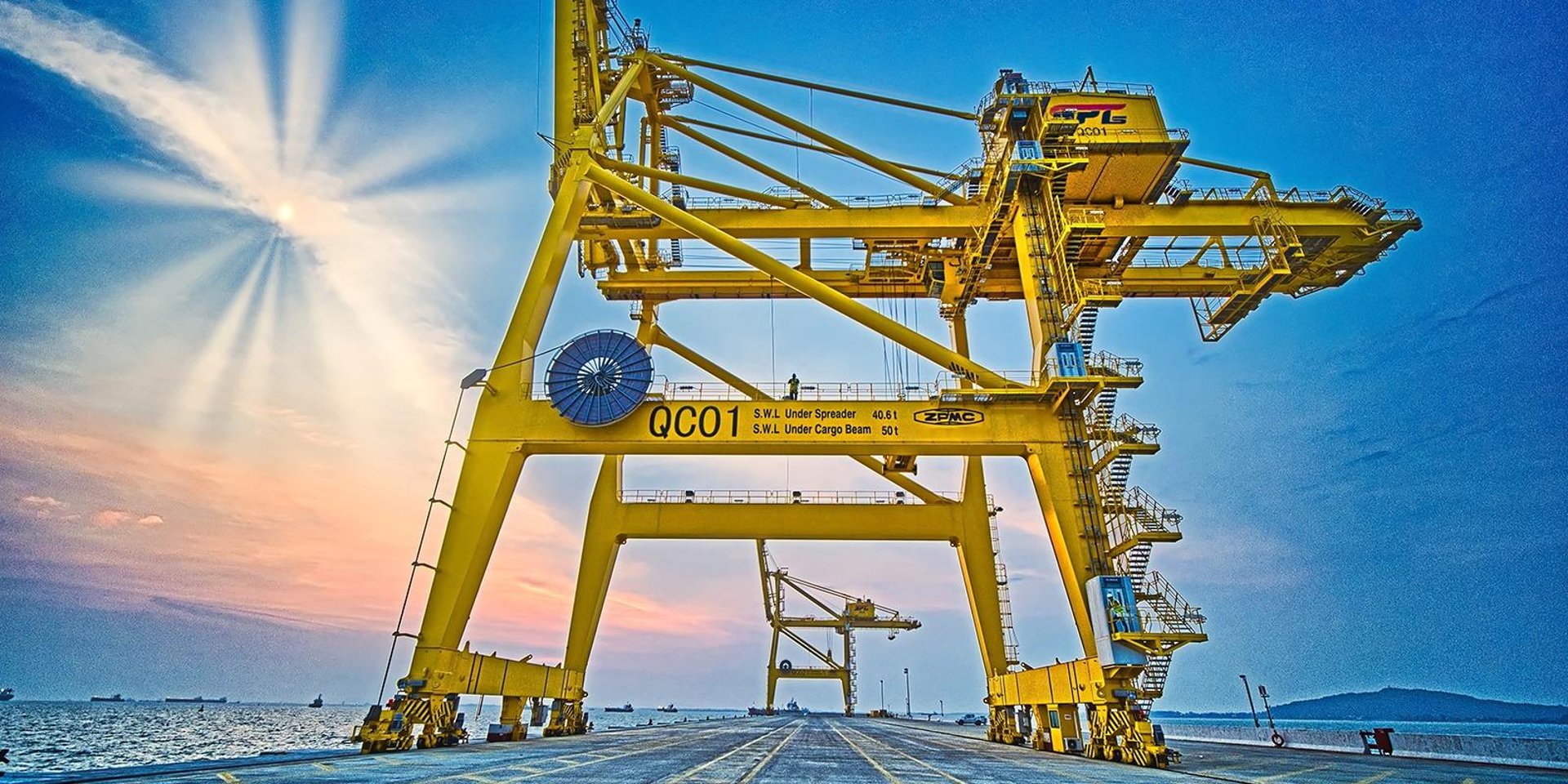
PROTOLON FL( N) TSFLCGEWOEU 3.66 kV Medium Voltage Flat Reeling Cable for High‑Stress Crane and Excavator Applications
PROTOLON FL (N) TSFLCGEWOEU is a 3.66 kV medium voltage flat reeling cable for cranes, container cranes and excavators, designed for high mechanical stress and reliability.
hongjing.Wang@Feichun
12/5/202523 min read
Product Overview
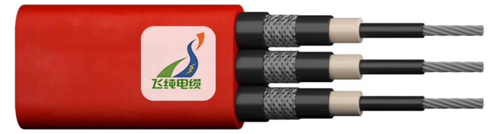
(N)TSFLCGEWOEU Medium Voltage Flat Reeling Cable
Medium voltage flat reeling cables represent a specialized category of power transmission solutions engineered specifically for mobile industrial equipment operating under demanding mechanical conditions. The NTSFLCGEWOEU medium voltage flat reeling cable is a 3.66 kV power cable designed to address the unique challenges faced by fast-moving container cranes, gantry cranes, excavators, and other heavy-duty material handling systems. Unlike conventional round cables, this flat reeling cable for crane applications features a parallel core arrangement that provides superior performance in applications requiring frequent directional changes within a single plane.
Flexible flat design for demanding reeling systems
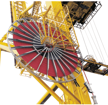
The flat geometric configuration of this medium voltage reeling cable offers distinct advantages over traditional round cable designs. The flat profile enables more efficient winding on reeling drums, reduces the overall space requirements in confined installation environments, and minimizes the tendency for cable twisting during operation. This flat reeling cable for excavators and cranes is specifically engineered to maintain flexibility while providing the mechanical robustness necessary for continuous duty cycles in industrial port environments and construction sites.
The cable's construction incorporates a parallel arrangement of insulated conductors positioned side-by-side rather than in a circular pattern. This design philosophy ensures consistent bending behavior regardless of the winding direction and facilitates better layer formation on cylindrical reeling drums. The flat geometry also improves cable guidance over support rollers and reduces the friction encountered during reeling and unreeling operations.
Optimised for continuous movement and heavy‑duty industrial use
Industrial material handling equipment operates under conditions that impose severe mechanical stresses on power cables. The NTSFLCGEWOEU flat reeling cable addresses these challenges through careful selection of materials and construction techniques. The cable is rated for continuous operation in applications where dynamic tensile loads, repeated bending cycles, and exposure to industrial environments are routine occurrences.
This medium voltage flat reeling cable for large mobile equipment delivers reliable electrical performance while withstanding the physical demands of high-speed crane operations. The design accommodates travel speeds up to 120 meters per minute in gantry reeling operations, making it suitable for modern high-throughput container terminals and industrial facilities where productivity requirements are continuously increasing.
Design and Construction Features
Flat parallel core arrangement with concentric earth conductor
The conductor arrangement in this flat medium voltage reeling cable follows a parallel configuration where individual insulated power conductors are positioned alongside each other in a single plane. This arrangement differs fundamentally from the concentrically stranded designs found in round cables. The power conductors are manufactured from tinned copper using fine stranding techniques (Class 5 according to DIN EN 60228) to ensure adequate flexibility for reeling applications.
A distinctive feature of this construction is the implementation of a concentric protective earth conductor system. Rather than incorporating a single large earth conductor, the design distributes the earth conductor around each individual power core. This concentric earth arrangement provides several technical advantages: it ensures symmetrical electrical field distribution around each conductor, improves overall mechanical stability of the cable structure, and facilitates uniform current distribution during fault conditions.
The flat parallel arrangement allows for predictable bending behavior and consistent performance when the cable traverses support rollers or winds onto reeling drums. This geometric configuration minimizes internal stress concentrations that can develop in round cables when subjected to tight bending radii or frequent direction changes.
EPR‑insulated medium voltage cores for reliable electrical performance
The insulation system employed in this 3.66 kV medium voltage flat reeling cable utilizes ethylene propylene rubber (EPR) compounds specifically formulated for demanding industrial applications. EPR insulation provides excellent electrical properties combined with superior mechanical characteristics essential for cables subjected to continuous flexing and mechanical stress.
Each power conductor receives an extruded EPR insulation layer that meets the voltage rating requirements for the cable's intended application. The EPR compound offers outstanding resistance to thermal aging, maintains flexibility across a wide temperature range, and demonstrates robust performance when exposed to moisture and typical industrial contaminants.
The insulation thickness and compound formulation are engineered to provide adequate dielectric strength while maintaining the overall cable flexibility necessary for reeling operations. EPR's inherent elastomeric properties ensure that the insulation can withstand repeated compression and expansion cycles without developing internal voids or cracks that could compromise electrical integrity.
Robust rubber outer sheath for abrasion and impact resistance
The outer protective sheath of this flat reeling cable for fast‑moving container cranes consists of a specially formulated rubber compound designed to withstand the harsh conditions encountered in industrial environments. This sheath material provides critical protection against mechanical damage from abrasion, impact, and environmental exposure.
The rubber compound incorporates properties that resist degradation from exposure to oils, moisture, ozone, and ultraviolet radiation. These characteristics are particularly important for cables installed in outdoor applications or in industrial settings where contact with hydraulic fluids, lubricants, and other chemical substances may occur.
The sheath design includes sufficient thickness to provide mechanical protection while maintaining overall cable flexibility. The material selection balances tear resistance, which prevents damage propagation from superficial cuts or nicks, with abrasion resistance to withstand the wear that occurs as the cable moves across support surfaces or winds onto reeling drums.
Red sheath colour for clear visual identification in crane systems
The outer sheath of this medium voltage reeling cable features a distinctive red color that serves both practical and safety functions. The red coloration provides immediate visual identification of the cable as a medium voltage power conductor, helping maintenance personnel and operators quickly distinguish it from low voltage control cables, communication lines, and other services that may be present in complex industrial installations.
This color coding convention aligns with industry practices for medium voltage equipment identification and contributes to overall workplace safety. The red sheath color remains stable throughout the cable's service life, even when exposed to sunlight, industrial atmospheres, and cleaning processes, ensuring that the visual identification remains effective over time.
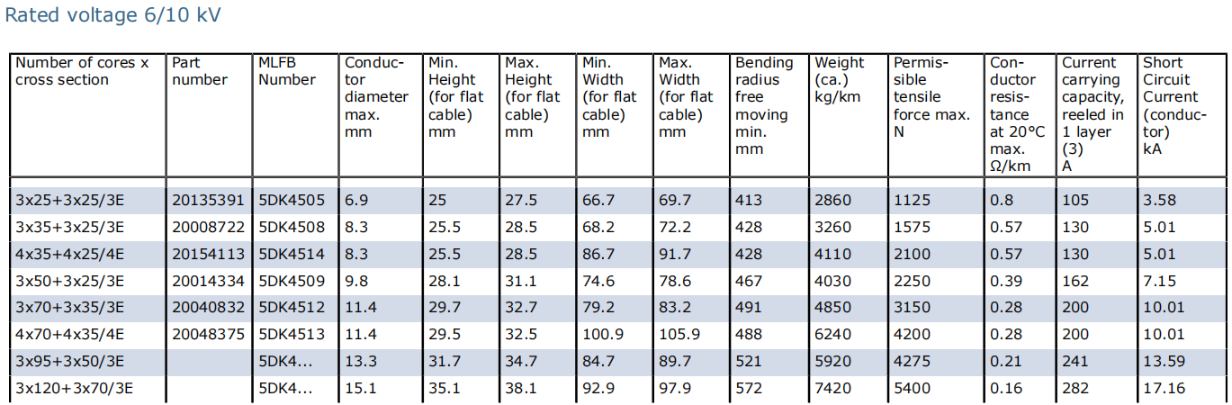
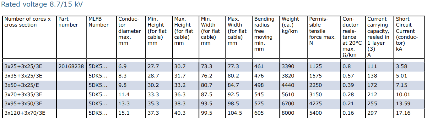
Electrical Characteristics of PROTOLON FL NTSFLCGEWOEU
Rated voltage class: 3.66 kV medium voltage flat reeling cable
The cable's rated voltage designation of 3.66 kV (expressed as 3.6/6 kV in U₀/U notation) indicates its suitability for medium voltage power distribution systems commonly found in industrial installations. This voltage rating represents the cable's continuous operating voltage capability, with U₀ indicating the voltage between any conductor and earth (3.6 kV) and U representing the voltage between any two conductors (6 kV).
This voltage classification places the cable in the medium voltage category suitable for connecting mobile equipment to power distribution systems operating at voltages above low voltage (typically below 1 kV) but below high voltage transmission levels. The 3.66 kV flat crane cable serves applications where increased voltage levels enable more efficient power transmission to high-capacity electric motors driving crane mechanisms and excavator hydraulic pumps.
The cable's voltage rating includes appropriate safety margins to accommodate the voltage variations that occur during normal system operation. Maximum permissible operating voltages of 4.2/7.2 kV (AC) and 5.4/10.8 kV (DC) allow for transient overvoltages and ensure reliable operation across the full range of expected service conditions.
Electrical field control with inner and outer semiconductive layers
A critical aspect of medium voltage cable design involves managing the electrical field distribution within and around the insulated conductors. This flat medium voltage reeling cable incorporates both inner and outer semiconductive layers that work in conjunction with the EPR insulation to control electrical field stress concentrations.
The inner semiconductive layer, positioned between the conductor surface and the insulation, eliminates air gaps that could exist between the stranded conductor and the insulation. These air gaps, if present, would create regions of high electrical field stress that could lead to partial discharge activity and premature insulation failure. The semiconductive layer ensures a smooth, uniform interface between the metallic conductor and the dielectric insulation.
The outer semiconductive layer serves multiple functions in the cable construction. It provides a conductive path around the outer surface of the insulation, ensuring that the electrical field remains radial and uniform. This layer connects to the concentric earth conductor system, providing a low-resistance path for fault currents and contributing to personnel safety by maintaining the outer cable surface at earth potential during normal operation.
These semiconductive layers also facilitate cable termination and jointing operations. The outer semiconductive layer can be removed ("stripped") at termination points to accommodate connection hardware, while the smooth interface between the semiconductive layers and the insulation prevents stress concentrations at the edges of the termination components.
Stable performance under frequent reeling and unreeling cycles
The electrical design of this 3.66 kV flat crane reeling cable accounts for the unique stresses imposed by continuous reeling and unreeling operations. During these movements, the cable experiences repeated bending cycles that subject the internal components to mechanical stress. The insulation system and overall construction must maintain electrical integrity despite these mechanical demands.
The EPR insulation compound selected for this application demonstrates excellent resistance to the development of internal cracks or voids that could occur due to repeated flexing. The material's elastomeric properties allow it to recover its original state after each bending cycle, preventing the accumulation of mechanical damage that would eventually compromise electrical performance.
The concentric earth conductor arrangement contributes to electrical stability by maintaining a consistent ground reference around each power conductor throughout the bending cycles. This design prevents the development of asymmetric field distributions that could accelerate insulation aging or create localized stress concentrations.
Mechanical Performance under High Mechanical Stresses
Designed for dynamic tensile loads in moving machinery
Mobile industrial equipment subjects power cables to tensile forces that vary throughout the operating cycle. As cranes traverse their rails or excavators reposition, the suspended cable length changes, creating dynamic loading conditions. The NTSFLCGEWOEU flat reeling cable construction accounts for these variable tensile loads through careful material selection and structural design.
The cable can withstand tensile loads up to 15 N/mm² applied to the conductor cross-section during normal operation. This loading capacity allows the cable to support its own weight over suspended spans while maintaining adequate mechanical integrity. The flat geometry distributes tensile forces more evenly across the parallel conductor arrangement compared to circular cable designs where outer conductors may bear disproportionate loads.
The rubber sheath and internal cable structure work together to prevent excessive elongation under load. While some stretching occurs as tensile forces increase, the design limits permanent deformation that would lead to progressive cable degradation. The cable construction incorporates sufficient mechanical strength to prevent conductor pullout from terminations during high-load scenarios while maintaining the flexibility necessary for continuous reeling operations.
Suitable for frequent changes of direction within one plane
A distinguishing characteristic of flat reeling cables is their optimized performance when directional changes occur within a single geometric plane. The flat crane reeling cable excels in applications where the cable must navigate horizontal or vertical plane transitions without rotating the cable body about its longitudinal axis.
Container cranes, for example, require cables that can follow the crane's movement along the dock while simultaneously accommodating the trolley's transverse motion. These combined movements create complex cable paths that demand stable bending behavior. The flat profile ensures that the cable bends consistently in its preferred plane, reducing the tendency for edge curling or twisting that can occur with improperly oriented round cables.
The parallel conductor arrangement means that all power conductors experience similar bending stress magnitudes during directional changes. This uniform stress distribution contrasts with round cable behavior where outer-layer conductors undergo greater displacement than inner conductors during bending. The result is more predictable mechanical performance and extended service life in applications involving frequent directional transitions.
Performance when running over rollers in reeling systems
Many reeling cable installations incorporate roller systems to guide the cable between the reeling drum and the mobile equipment. These rollers support the cable's weight, reduce friction during movement, and help maintain proper cable alignment. The flat geometry of this medium voltage reeling cable provides advantages in roller-guided installations.
The wide, flat profile creates a larger contact area with support rollers compared to round cables of equivalent conductor cross-section. This increased contact area distributes the cable's weight more evenly, reducing the localized pressure that can cause sheath deformation or internal conductor damage. The flat surface also experiences less tendency to slip or walk along the roller axis, promoting stable cable guidance.
The cable's construction withstands the compressive forces that develop at roller contact points. The rubber sheath provides cushioning that prevents transmission of shock loads directly to the internal conductors and insulation. The flat configuration also reduces the cable's tendency to bounce or vibrate when traversing rollers at high speeds, contributing to smooth, quiet operation even in high-throughput applications.
Optimised flat geometry for tight reeling spaces and drum systems
Space constraints frequently influence cable system design in industrial installations. Electrical rooms, equipment enclosures, and machinery housings often provide limited clearance for reeling drum assemblies. The flat profile of this reeling cable offers practical advantages in space-restricted applications.
When wound onto a cylindrical reel, the flat cable creates a more compact drum profile than equivalent round cables. The reduced build-up per winding layer allows either longer cable lengths to be stored on a given drum diameter or permits the use of smaller-diameter drums for a specified cable length. This characteristic proves particularly valuable in retrofitting older equipment where physical space for cable reels cannot be expanded.
The flat geometry facilitates orderly layer winding on reeling drums without specialized grooving or guidance mechanisms. Each winding layer naturally aligns adjacent to the previous wrap, creating a stable, organized drum fill pattern. This self-organizing characteristic reduces the need for active cable guidance systems and minimizes the risk of cable crossover conditions that can damage cable sheaths or cause operational malfunctions.
Typical Applications of NTSFLCGEWOEU Flat Reeling Cable
Fast‑moving container cranes and gantry cranes
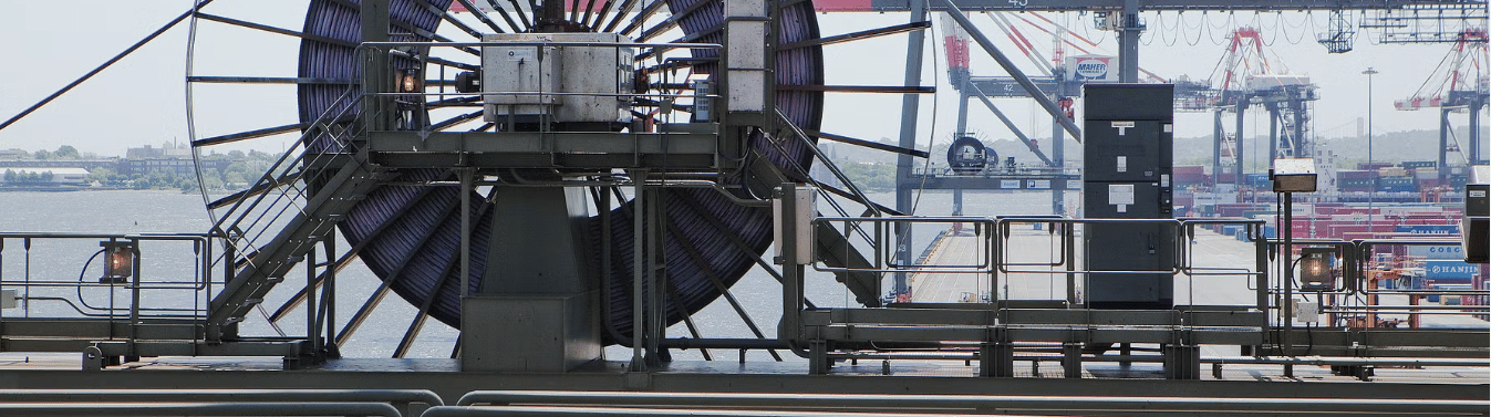
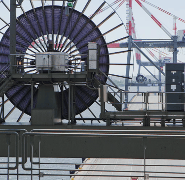
Modern container terminals operate under intense productivity pressures that demand high-speed, reliable crane operations. Ship-to-shore gantry cranes, rail-mounted gantry cranes, and rubber-tired gantry cranes employ this flat medium voltage reeling cable to power their main hoisting mechanisms, trolley drives, and auxiliary systems. The cable's ability to withstand continuous cycling at speeds approaching 120 meters per minute makes it well-suited for these demanding applications.
Container handling cranes present particularly challenging cable service conditions due to their high duty cycles, extended travel distances, and exposure to marine environments. The NTSFLCGEWOEU cable construction addresses these challenges through its combination of mechanical robustness, electrical reliability, and environmental resistance. The flat design proves especially beneficial in container crane applications where long cable runs must be managed efficiently within confined trolley structures.
General cranes in ports, yards and industrial plants
Beyond specialized container handling equipment, various overhead cranes, jib cranes, and portal cranes utilized throughout port facilities and industrial manufacturing plants benefit from this flat reeling cable design. Steel mills, shipyards, automotive manufacturing facilities, and heavy machinery plants employ overhead crane systems that rely on medium voltage cables for main power distribution.
These general industrial crane applications often involve variable duty cycles, diverse environmental conditions, and extended service life requirements. The cable's EPR insulation and robust sheath construction provide the durability necessary for reliable long-term operation. The 3.66 kV voltage rating matches the power distribution infrastructure commonly found in large industrial facilities, facilitating straightforward integration into existing electrical systems.
Large mobile equipment and material handling systems
Mining operations, large construction projects, and bulk material handling facilities utilize mobile equipment such as bucket-wheel excavators, stacker-reclaimers, and mobile ship loaders. This flat medium voltage reeling cable for large mobile equipment provides the electrical connection between stationary power sources and the equipment's drive systems as they move along their operational paths.
These applications frequently involve extended cable lengths, harsh environmental exposure, and contamination from dust, moisture, and transported materials. The cable's rubber sheath formulation resists degradation from these environmental factors while maintaining mechanical flexibility. The medium voltage rating enables efficient power transmission across the longer distances typical of large mobile equipment installations.
Excavators and heavy construction machinery with reeling systems
Large hydraulic excavators employed in mining, quarrying, and major construction projects increasingly utilize electric drive systems rather than diesel engines. These electric excavators require reliable power cables that can accommodate the machine's movement during operation. The flat reeling cable for excavators and cranes provides the necessary power connection while withstanding the mechanical stresses imposed by excavator positioning and operation.
The cable's flexibility and fatigue resistance prove critical in excavator applications where continuous digging cycles subject the cable to repeated bending, tensioning, and relaxation. The flat profile facilitates cable management on excavator-mounted reeling systems where space constraints limit the diameter of cable drums. The robust construction withstands the vibration, shock loading, and environmental exposure characteristic of heavy construction equipment operation.
Advantages of Flat Medium Voltage Reeling Cables vs. Conventional Designs
Better layer winding and guidance on reeling drums
Conventional round medium voltage cables require careful attention to winding patterns to prevent the development of crossovers, gaps, or uneven drum loading. These winding imperfections can lead to cable damage, inconsistent drum performance, and reduced cable service life. The flat cable geometry inherently promotes orderly, uniform winding behavior.
As the flat cable wraps around the drum surface, its wide profile naturally positions each wrap adjacent to the previous turn, creating a self-organized winding pattern. This characteristic reduces dependence on active cable guidance systems and minimizes operator intervention requirements during cable spooling operations. The consistent winding pattern also prevents the development of high-pressure contact points between cable layers that can cause sheath deformation in conventional round cables.
The flat profile's winding characteristics prove particularly advantageous in applications where cable length varies significantly during the operational cycle. Container crane operations, for example, may wind and unwind dozens of meters of cable during each loading or unloading sequence. The flat cable's stable winding behavior ensures reliable performance throughout these high-cycle operations.
Reduced cable twisting and improved guidance over rollers
Round cables subjected to tensile loads while navigating directional changes exhibit a natural tendency to twist about their longitudinal axis. This twisting behavior can lead to cable kinking, inconsistent bending behavior, and accelerated mechanical wear. The flat reeling cable's geometry significantly reduces twisting tendencies during operation.
The wide, flat profile provides inherent torsional resistance that helps maintain cable orientation as it moves through the system. When the cable encounters support rollers or drum edges, its broad face resists rotation, keeping the cable properly aligned within the guidance system. This rotational stability reduces wear on both the cable sheath and the support infrastructure.
The flat surface contact with guide rollers creates a more stable mechanical interface than the line contact characteristic of round cables. This enhanced contact area distributes support forces more evenly and reduces the localized pressure that can contribute to premature wear. The result is smoother cable movement, reduced friction, and extended service life for both the cable and the associated guidance equipment.
Higher reliability in continuous crane duty cycles
Modern industrial operations increasingly demand continuous-duty performance from crane and material handling systems. Equipment utilization rates continue to rise as facilities seek to maximize throughput and return on capital investment. These operational demands place corresponding stress on the electrical infrastructure supporting mobile equipment.
The flat medium voltage reeling cable construction addresses continuous-duty requirements through careful material selection and structural design. The EPR insulation system maintains electrical integrity despite repeated thermal cycling and mechanical flexing. The robust sheath construction protects internal components from environmental damage while providing the mechanical toughness necessary to survive continuous operation.
Field experience demonstrates that properly designed and installed flat reeling cables can achieve service lives extending multiple years in high-duty-cycle applications. This reliability stems from the cable's ability to dissipate heat effectively, resist mechanical fatigue, and maintain electrical performance despite the accumulated stress of continuous operation.
Optimised for installations with limited vertical space
Equipment designers and facility planners frequently confront physical space limitations that constrain cable system design options. Vertical clearance restrictions prove particularly challenging, as they limit the diameter of reeling drum assemblies and reduce the available space for cable routing. The flat cable profile offers distinct advantages in these space-constrained scenarios.
The reduced drum build-up height achieved with flat cables enables the use of smaller-diameter reeling systems or permits longer cable lengths within a fixed-diameter drum constraint. This characteristic proves valuable in retrofit applications where existing equipment housings cannot be enlarged and in new equipment designs where overall envelope dimensions influence market competitiveness.
Additionally, the flat profile facilitates cable routing through tight clearances and around obstacles that would be difficult or impossible to navigate with larger-diameter round cables. The cable's ability to conform to flat surfaces and navigate restricted passages expands the range of feasible installation configurations available to system designers.
Installation and Operating Recommendations
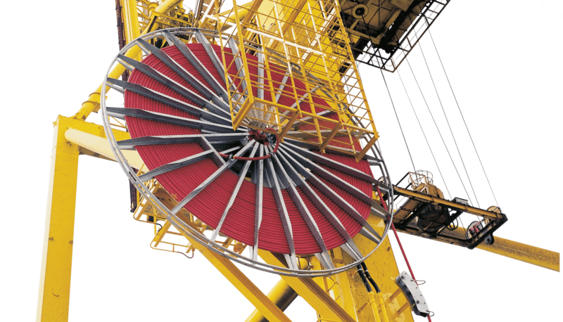
Recommended use in gantry reeling operation (up to 120 m/min)
Installation of this flat crane cable in gantry reeling systems requires attention to several key parameters to ensure optimal performance. The maximum recommended travel speed of 120 meters per minute establishes a performance envelope suitable for most modern crane operations. Applications requiring higher speeds should involve consultation with cable manufacturers to assess specific operating conditions and potential design modifications.
The cable should be installed with appropriate tensioning to prevent slack accumulation on the reeling drum while avoiding excessive tension that could stress the conductors. Initial installation typically involves manually or mechanically winding the cable onto the drum while maintaining moderate tension throughout the spooling process. The first few wraps should be secured to the drum core using appropriate fastening methods that prevent cable slippage during operation.
Cable entry and exit points require careful attention to ensure smooth transitions between the stationary installation and the moving cable sections. Cable routing should avoid sharp edges or protrusions that could damage the sheath during movement. Support roller locations and spacing should be selected to prevent excessive unsupported cable spans that could lead to sagging or bouncing during high-speed operations.
Guidelines for minimum bending radius and S‑type directional changes
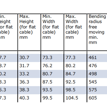
Bending stress represents one of the primary mechanical loads experienced by reeling cables during operation. Excessive bending can damage conductors, stress insulation, and reduce overall cable service life. The minimum bending radius for this flat cable should be maintained at or above specified values based on the cable's maximum height dimension.
For this flat cable design, it is recommended to calculate bending radius limits using 1.5 times the cable's maximum height as the effective diameter reference. This approach accounts for the asymmetric cross-section and ensures adequate protection of the internal components during bending cycles. Fixed installations typically require minimum bending radii of 5 to 6 times this effective diameter, while reeling operations with forced guidance may require 10 to 12 times the effective diameter.
S-type directional changes, where the cable reverses its bending direction within a relatively short distance, impose particularly severe mechanical stress. The minimum distance between inflection points in S-type bends should be maintained at 20 times the effective cable diameter. This spacing allows adequate stress relief between opposing bending regions and prevents the accumulation of mechanical fatigue damage that could lead to premature cable failure.
Considerations for routing over rollers and support systems
Roller support systems provide essential cable guidance in many reeling applications, but improper roller configuration can contribute to cable damage. Support rollers should feature smooth, rounded surfaces free from burrs or sharp edges that could abrade the cable sheath. Roller diameter should be sufficiently large to avoid excessive cable bending at the contact point—minimum roller diameters of 7.5 times the effective cable diameter are generally appropriate.
Roller spacing requires careful consideration to balance support effectiveness against system complexity. Excessively wide roller spacing permits cable sagging between support points, leading to uncontrolled motion and potential impact damage. Conversely, unnecessarily close roller spacing increases system cost and creates additional friction points that impede cable movement. Optimal roller spacing typically ranges from one to three meters depending on cable weight, tensile load conditions, and operational speed.
Roller alignment proves critical for smooth cable operation. Misaligned rollers can cause the cable to track incorrectly, leading to edge wear and increased friction. Support roller axes should be positioned perpendicular to the intended cable path, and roller surfaces should be kept clean and free from accumulated debris that could interfere with smooth cable movement.
Ambient temperature range and environmental conditions (UV, moisture, oil)
The cable's rubber sheath formulation provides protection across a broad ambient temperature range. During fully flexible operation in reeling applications, the cable maintains performance from -35°C to +80°C. Fixed installations, where the cable remains stationary, can accommodate temperatures from -50°C to +80°C. These temperature limits ensure adequate sheath flexibility for installation and operation while preventing thermal degradation of the insulation and sheath materials.
Outdoor installations expose cables to ultraviolet radiation from sunlight, which can degrade many polymer materials over time. The rubber compound used in this cable's outer sheath incorporates UV-resistant additives that extend service life in outdoor applications. However, continuous direct sunlight exposure, particularly in tropical climates, may elevate sheath surface temperatures significantly above ambient air temperature, potentially affecting cable current-carrying capacity.
Moisture exposure, whether from rain, humidity, or equipment washing operations, poses limited risk to properly constructed and installed cables. The outer sheath provides a water-resistant barrier that prevents moisture ingress to the cable interior. However, cable termination points and mechanical entry seals require proper installation to prevent water intrusion at these vulnerable locations.
Industrial environments frequently involve exposure to oils, hydraulic fluids, and other chemical substances. The cable sheath demonstrates resistance to commonly encountered industrial oils and lubricants, maintaining its mechanical properties despite occasional contact. Continuous immersion in aggressive chemicals or prolonged exposure to concentrated substances may require evaluation of specific compatibility to ensure adequate service life.
Standards and Compliance
Type designation NTSFLCGEWOEU based on DIN VDE 0250‑813
The cable type designation NTSFLCGEWOEU follows the coding system established by DIN VDE standards for identifying cable construction characteristics. This alphanumeric code provides a concise description of the cable's key design elements. The designation can be decoded as follows:
N: Design conforms to corresponding German VDE standards
TS: Medium voltage reeling cable construction
FL: Flat cable geometry
C: Conducting (semiconductive) layer over insulation
G: Rubber-type insulation material
E: Rubber-based protective earth conductor covering
W: Weather-resistant outer sheath
Ö: Oil-resistant outer sheath
U: Flame-retardant outer sheath properties
This standardized designation system enables clear communication of cable specifications across manufacturers, installers, and end users. It provides assurance that the cable construction meets established technical requirements and facilitates proper cable selection for specific applications.
Classification as a medium voltage flat reeling cable for cranes
The cable falls within the medium voltage category based on its 3.6/6 kV voltage rating, distinguishing it from low voltage cables (typically below 1 kV) and high voltage cables (generally above 35 kV). This medium voltage classification reflects the cable's intended use in industrial power distribution systems serving large electric motors and substantial electrical loads.
The reeling cable classification indicates the cable's suitability for applications involving continuous winding and unwinding operations on drum-type cable management systems. This designation distinguishes reeling cables from fixed installation cables, trailing cables for dragging applications, and festoon cables for other mobile power applications. The reeling cable classification implies specific mechanical performance requirements related to flexibility, fatigue resistance, and drum winding behavior.
The crane application designation reflects the cable's design optimization for the specific mechanical and electrical demands of overhead crane systems and related material handling equipment. Crane cables must accommodate frequent starting and stopping, varied duty cycles, and the mechanical stresses associated with suspended cable operation.
Suitability for indoor and outdoor industrial environments
The cable construction provides adequate environmental protection for both indoor and outdoor installations in industrial facilities. Indoor applications typically involve less severe environmental exposure but may include challenges such as elevated temperatures, airborne contamination, and exposure to process chemicals. The cable's material selection addresses these indoor environmental factors.
Outdoor installations introduce additional environmental considerations including sunlight exposure, temperature extremes, precipitation, and potentially corrosive atmospheric conditions in coastal or industrial areas. The cable's rubber sheath incorporates weather-resistant properties that maintain performance despite these environmental stresses. The UV-resistant sheath formulation prevents surface degradation from prolonged sunlight exposure, while the moisture-resistant construction protects internal components from water intrusion.
Industrial environments, whether indoor or outdoor, frequently involve exposure to oils, coolants, and other process fluids. The cable sheath demonstrates resistance to commonly encountered industrial substances, maintaining its protective function despite incidental contact with these materials. This chemical resistance contributes to extended service life in typical industrial operating conditions.
Selection Guide for PROTOLON FL NTSFLCGEWOEU
Choosing suitable cross‑sections for crane and reeler loads
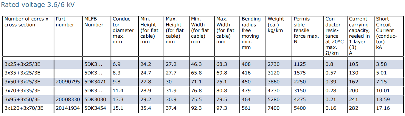
Conductor cross-section selection represents a critical specification decision that influences both initial cable cost and long-term system performance. The selection process must consider several technical factors including current-carrying requirements, voltage drop limitations, mechanical strength considerations, and short-circuit withstand capability.
The current-carrying capacity of the cable varies with conductor cross-section, installation method, and ambient temperature conditions. Applications requiring continuous high current loads demand larger conductor cross-sections to prevent excessive temperature rise that could degrade insulation or reduce cable service life. The cable manufacturer's published current ratings provide guidance for specific cross-sections under various installation conditions.
Voltage drop calculations ensure that the cable impedance does not cause excessive voltage reduction between the power source and the connected load. Large cranes and excavators often operate at considerable distances from their power sources, making voltage drop a significant concern. Larger conductor cross-sections reduce cable resistance and thereby minimize voltage drop, ensuring adequate voltage delivery to motor drives and control systems.
Mechanical considerations also influence cross-section selection. The cable must possess sufficient mechanical strength to support its own weight in suspended applications while accommodating the tensile loads imposed during movement. Larger conductor cross-sections inherently provide greater mechanical strength, though this benefit must be balanced against increased cable weight, reduced flexibility, and higher cost.
Matching travel speed, mechanical stress, and duty cycle
The relationship between operating speed, mechanical stress levels, and duty cycle characteristics requires careful evaluation during cable selection. High-speed applications impose greater mechanical stress on cables due to increased inertial forces, higher acceleration loads, and more frequent bending cycles per unit time. These factors can accelerate mechanical wear and reduce service life if not properly addressed through appropriate cable design and installation practices.
Duty cycle characteristics significantly influence cable thermal performance and mechanical longevity. Equipment operating on continuous duty cycles accumulates heat in the cable conductors that must be dissipated to prevent excessive temperature rise. The cable's current rating accounts for this thermal behavior, with different ratings published for continuous duty versus intermittent operation where cooling periods permit higher peak currents.
Mechanical stress accumulation over the cable's service life determines its ultimate failure mode and achievable lifespan. Applications involving frequent starting and stopping, rapid acceleration and deceleration, or extreme tensile loading conditions may require enhanced cable constructions or shortened replacement intervals. Matching the cable specification to the actual operating profile ensures adequate performance throughout the intended service life.
Integration into existing crane power supply and control systems
Successful cable installation requires proper integration with existing electrical infrastructure including circuit protection devices, cable terminations, and control system interfaces. Medium voltage cables require specialized termination equipment that accommodates the EPR insulation system and provides environmental sealing. The cable manufacturer can provide guidance on compatible termination products and proper installation techniques.
Circuit protection coordination ensures that overcurrent protective devices adequately protect the cable from thermal damage during overload or short-circuit conditions without causing nuisance tripping during normal motor starting transients. The cable's short-circuit withstand capability must exceed the maximum available fault current at the installation location, considering the protective device clearing time.
Control system integration may involve coordination between the cable's electrical characteristics and the crane's motor drive systems. Variable frequency drives, for example, can impose high-frequency voltage stresses on cable insulation systems that differ from the cable's rated frequency performance. Proper selection of motor drive output filtering and cable routing practices helps ensure electromagnetic compatibility with adjacent control wiring and communication systems.
Common Issues and Solutions in MV Flat Reeling Cable Applications
How do I prevent cable damage from improper drum winding?
Improper drum winding represents one of the most common causes of premature cable failure in reeling applications. When cables wind unevenly or with crossovers, localized pressure concentrations develop that can damage the outer sheath and eventually compromise internal components. Several strategies help prevent winding-related damage.
First, ensure adequate initial tensioning during the first few drum wraps. A slack first layer creates an unstable foundation that promotes winding irregularities in subsequent layers. The initial wraps should be secured firmly to the drum core and maintained under moderate tension during the remainder of the winding process.
Second, verify that cable guide systems properly direct the cable onto the drum. Misaligned guides or worn guide components can cause the cable to approach the drum at incorrect angles, leading to poor winding patterns. Regular inspection and maintenance of guide rollers, fairleads, and alignment systems helps maintain proper cable positioning throughout its operational life.
What causes premature conductor fatigue in reeling cables?
Conductor fatigue develops when individual copper wires within the stranded conductor break due to accumulated flexing cycles. This failure mode typically results from excessive bending stress, inadequate conductor design for the application, or operation beyond the cable's rated mechanical performance envelope.
Bending stress can be reduced by maintaining bending radii above the manufacturer's minimum specifications. Applications requiring tight bending radii should utilize cables with finer conductor stranding (such as Class 6 instead of Class 5) that better accommodate repeated flexing. The cable installation should avoid compound bends where the cable experiences reversed bending within short distances.
Tensile loading contributes to conductor fatigue by superimposing axial stress onto bending stress. During bending under tension, the outer conductors experience higher stress than inner conductors, accelerating fatigue accumulation in the outer strands. Minimizing cable suspension lengths and ensuring proper support reduces tensile loads and extends conductor life.
How can I identify insulation degradation before failure occurs?
Early detection of insulation degradation enables proactive cable replacement before service interruptions occur. Several monitoring approaches can identify developing insulation problems before they progress to complete failure.
Periodic electrical testing using insulation resistance measurements (megohm testing) or more sophisticated techniques such as partial discharge testing can detect deteriorating insulation conditions. These tests should be scheduled regularly as part of preventive maintenance programs, with test frequencies determined by equipment criticality and operating conditions.
Visual inspection of the cable sheath during scheduled maintenance outages may reveal surface damage, cracking, or unusual wear patterns that suggest developing problems. Pay particular attention to areas where the cable traverses rollers, enters reeling drums, or experiences repeated bending cycles, as these locations experience the highest mechanical stress.
Thermographic inspection during operation can identify localized heating that may indicate developing electrical problems such as conductor damage or moisture intrusion. Unusual temperature patterns along the cable length warrant investigation and may justify more detailed electrical testing or cable replacement.
What environmental factors accelerate cable aging?
Multiple environmental factors contribute to cable aging and determine the achievable service life in specific applications. Understanding these factors enables better cable selection and installation practices that maximize operational longevity.
Temperature extremes, both hot and cold, accelerate aging processes in cable materials. Elevated temperatures increase the rate of chemical reactions that degrade polymeric insulation and sheath materials. Applications in high-ambient-temperature environments or those involving sustained high electrical loading should consider cables with enhanced thermal ratings or implement measures to improve cable cooling.
Ultraviolet radiation from sunlight gradually degrades many polymer materials through photochemical reactions. While the cable's rubber sheath incorporates UV-resistant additives, prolonged outdoor exposure in high-insolation environments can reduce service life. Where possible, provide shading for cable sections exposed to direct sunlight, or consider cables with enhanced UV-resistant sheath formulations for harsh outdoor environments.
Chemical exposure, particularly to aggressive industrial chemicals, solvents, or petroleum products, can attack sheath materials and compromise their protective function. While the cable demonstrates resistance to commonly encountered industrial oils, sustained exposure to aggressive chemicals may warrant material compatibility evaluation. Preventing chemical contact through proper cable routing or protective measures extends cable life in chemically harsh environments.
How do I address cable tracking issues on support rollers?
Cable tracking problems, where the cable fails to maintain proper alignment on support rollers, can lead to edge wear, increased friction, and potential cable damage. Several factors contribute to tracking issues, and corresponding solutions
How to Reach Us
Get in Touch
SiteMap
Product Catalogue
Festoon Cable
Shore Power Cable




Scan to add us on WeChat