
PROTOLON(FL)-LWL Medium Voltage Flat Reeling Cable: Complete Technical Guide for High-Performance Crane Operations
Discover the PROTOLON(FL)-LWL (N)TSFLCGEWOEU medium voltage flat reeling cable with integrated fiber-optics. Engineered for dynamic tensile loads, directional changes, and high mechanical stresses in mobile equipment applications. Explore technical specifications, design features, and performance capabilities for container cranes, excavators, and heavy machinery.
hongjing.Wang@Feichun
12/5/202512 min read
Advanced Cable Solutions for Heavy-Duty Mobile Equipment
The PROTOLON(FL)-LWL (N)TSFLCGEWOEU represents a specialized engineering solution for medium voltage power transmission combined with fiber-optic data communication in demanding industrial environments. This flat reeling cable addresses the complex requirements of modern material handling equipment, particularly in applications where simultaneous power delivery and high-speed data transmission are essential under extreme mechanical stress conditions.
Industrial operations involving fast-moving container cranes, large excavators, and heavy mobile equipment require cable systems capable of withstanding dynamic tensile loads, multiple directional changes within a single plane, and continuous operation over rollers. The integration of fiber-optic technology within a medium voltage power cable eliminates the need for separate communication infrastructure, reducing installation complexity while enhancing operational reliability.
Primary Application Environments
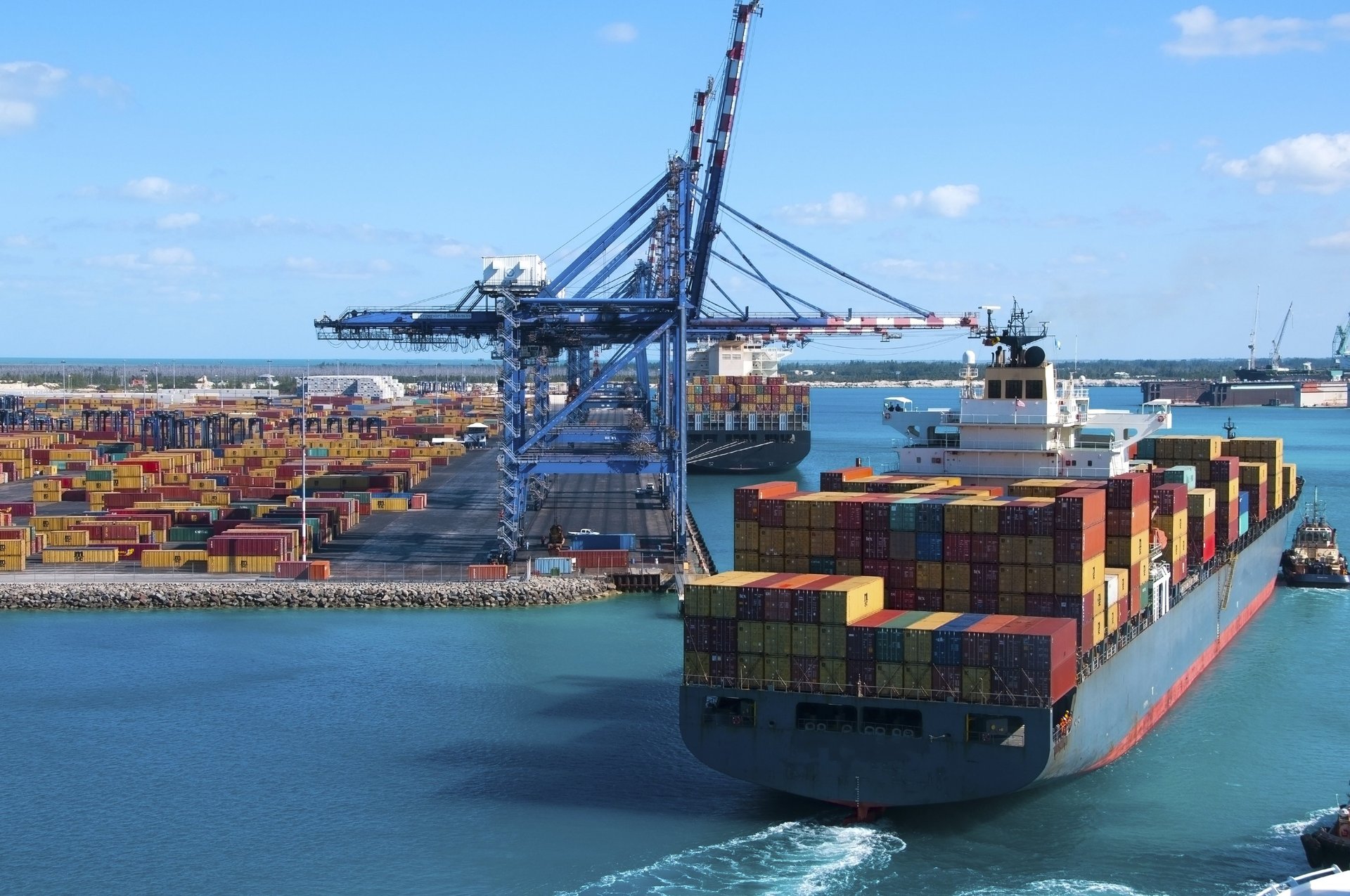
Medium voltage flat reeling cables with integrated fiber-optics serve critical functions in several specialized industrial sectors. Container terminal operations represent the most demanding application, where automated stacking cranes and ship-to-shore gantry systems require continuous power supply at voltages ranging from 3.6/6 kV to 12/20 kV, combined with real-time data communication for positioning systems, load monitoring, and automated control functions.
Mining and excavation operations utilize these cables for large mobile equipment including dragline excavators, bucket-wheel excavators, and mobile crushing stations. The flat cable profile proves advantageous in these applications, as the design accommodates frequent reeling operations with multiple direction changes while maintaining stable electrical and optical transmission characteristics.
Manufacturing facilities with overhead crane systems, particularly those handling heavy materials in steel production, automotive assembly, and aerospace manufacturing, benefit from the combined power and data transmission capabilities. The fiber-optic integration supports advanced crane management systems, collision avoidance technology, and automated load positioning without requiring separate cable runs.
Core Design Architecture and Construction Features
Conductor System Configuration
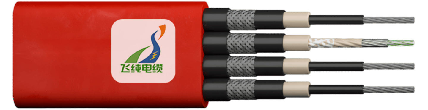
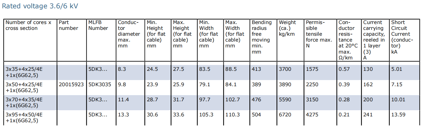
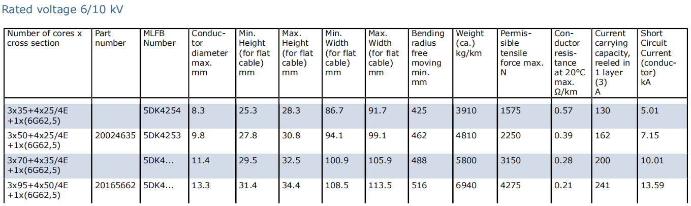
The conductor system employs electrolytic copper that undergoes tin plating for enhanced corrosion resistance. The finely stranded construction follows Class F specifications according to DIN VDE 0295, providing the flexibility necessary for continuous reeling operations while maintaining excellent electrical conductivity. Cross-sections range from 25 mm² to 300 mm², with common configurations including 3x35+4x25/4E, 3x50+4x25/4E, and 3x70+4x35/4E arrangements.
The protective earth conductor features a split configuration, distributed concentrically around each power core. This arrangement provides several advantages: improved mechanical strength through load distribution, enhanced electrical safety through redundant grounding paths, and better electromagnetic compatibility through symmetrical conductor geometry. The parallel core arrangement characteristic of flat cable designs optimizes the cable profile for reeling applications where bending occurs predominantly in one plane.
Insulation System and Field Control
The insulation system utilizes PROTOLON compound, a specialized formulation based on high-quality ethylene propylene rubber (EPR) meeting minimum 3GI3 grade specifications. This material selection provides superior mechanical properties, excellent electrical characteristics across the voltage range, and enhanced resistance to thermal degradation during sustained operation.
Electrical field control incorporates both inner and outer semiconductive layers. The inner semiconductive layer, manufactured from EPR-based material, prevents excessive electrical field concentration at individual conductor wires, eliminating potential partial discharge sites. The outer semiconductive layer uses modified EPR formulation designed for warm-removable characteristics, significantly simplifying cable termination procedures while maintaining intimate contact with the insulation during operation.
The semiconductive layers serve multiple critical functions beyond field grading. They provide protection against electrical shock hazards, prevent partial discharges within the conductor assembly, ensure radial electrical field distribution throughout the insulation, and facilitate current discharge during fault conditions. The outer semiconductive layer integrates with the protective earth conductor system, with resistance between the earth conductor and any point on the outer semiconductive layer maintained below 500 ohms.
Fiber-Optic Integration Architecture
The optical transmission system consists of six individual tubes arranged around a central support element, with each tube containing one, two, or three optical fibers depending on system requirements. Standard configurations include 6-fiber, 12-fiber, 18-fiber, and 24-fiber arrangements, accommodating diverse communication bandwidth requirements.
Three distinct fiber types are available to match specific application needs:
Multimode Graded-Index G62.5/125 μm Fiber: This widely deployed fiber type features a 62.5 μm core diameter with 125 μm cladding and 250 μm coating diameter. Attenuation characteristics include maximum 3.3 dB/km at 850 nm wavelength and 0.9 dB/km at 1310 nm. Bandwidth capabilities reach 400 MHz at 850 nm and 600 MHz at 1300 nm, with numerical aperture of 0.275 ± 0.02. These specifications support moderate-distance data transmission suitable for most industrial control applications.
Multimode Graded-Index G50/125 μm Fiber: Representing enhanced performance, this fiber type maintains the same dimensional specifications but delivers superior attenuation of 2.8 dB/km at 850 nm and 0.8 dB/km at 1310 nm. Bandwidth capacity significantly improves to 1200 MHz at 1300 nm, supporting higher data rates over extended distances. The numerical aperture of 0.2 ± 0.02 provides improved modal distribution for better transmission characteristics.
Monomode Single-Mode E9/125 μm Fiber: For applications requiring maximum transmission distance and bandwidth, single-mode fiber offers exceptional performance with attenuation of only 0.4 dB/km at 1310 nm and 0.3 dB/km at 1550 nm. Chromatic dispersion remains below 3.5 ps/nm·km at both 1310 nm and 1550 nm wavelengths, enabling transmission over multiple kilometers without signal regeneration.
Each fiber receives individual identification through a specially developed color coding system, facilitating accurate termination and maintenance procedures. The hollow core structure employs ETFE (7YI 1 compound) filling material, protecting fibers from moisture ingress, mechanical stress, and environmental contaminants while maintaining flexibility for reeling applications.
Sheath System and Mechanical Protection
The cable sheath employs PROTOFIRM special compound, a chloroprene rubber (CR) based formulation meeting minimum 5GM5 quality grade specifications. This material selection provides exceptional resistance to abrasion, tearing, ozone degradation, ultraviolet radiation, and oil contamination. The distinctive red coloring facilitates visual identification of medium voltage cables in complex industrial installations.
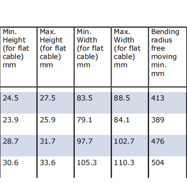
Polyester fiber reinforcement layers integrate throughout the sheath structure, dramatically enhancing tensile strength and tear resistance. This reinforcement enables the cable to withstand tensile loads up to 15 N/mm² on the conductor cross-section, with permissible tensile forces ranging from 1,575 N for 3x35 mm² configurations to 5,400 N for 3x120 mm² arrangements.
Electrical Specifications and Performance Characteristics
Voltage Ratings and Operating Parameters
The cable system accommodates multiple voltage configurations:
3.6/6 kV Configuration: Rated voltage 3.6 kV, maximum AC operating voltage 4.2/7.2 kV, maximum DC operating voltage 5.4/10.8 kV, AC test voltage 11 kV
6/10 kV Configuration: Rated voltage 6.0 kV, maximum AC operating voltage 6.9/12 kV, maximum DC operating voltage 9/18 kV, AC test voltage 17 kV
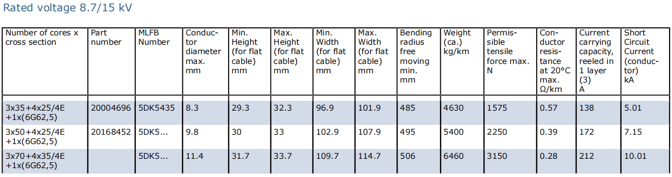
8.7/15 kV Configuration: Rated voltage 8.7 kV, maximum AC operating voltage 10.4/18 kV, maximum DC operating voltage 13.5/27 kV, AC test voltage 24 kV
Higher voltage ratings including 12/20 kV configurations are available upon request, extending the application range to large-scale mining operations and industrial facilities with elevated distribution voltages.
Current Carrying Capacity and Thermal Management
Current carrying capacity varies by conductor cross-section and installation method. For cables reeled in a single layer at 30°C ambient temperature, representative values include: 130 A for 3x35 mm² configuration, 162 A for 3x50 mm², 200 A for 3x70 mm², and 282 A for 3x120 mm² arrangements.
The maximum permissible conductor temperature during continuous operation is 90°C, with short-circuit temperature limits of 250°C. The cable maintains operational capability across ambient temperature ranges from -50°C to +80°C for fixed installation, with fully flexible operation supported from -35°C to +80°C.
Thermal management considerations include derating factors for varying ambient temperatures, grouping arrangements, and installation methods. When multiple cables are installed in close proximity, appropriate derating ensures reliable operation without exceeding thermal limits. The flat cable profile provides advantageous heat dissipation characteristics compared to round cable equivalents, as the increased surface area facilitates more efficient cooling.
Mechanical Performance and Installation Guidelines
Tensile Load Management
The maximum tensile load on conductors is limited to 15 N/mm² under normal operating conditions. This translates to permissible tensile forces of 1,575 N for 3x25 mm² configuration, 2,250 N for 3x50 mm², 3,150 N for 3x70 mm², 4,275 N for 3x95 mm², and 5,400 N for 3x120 mm² arrangements. These values represent the combined static and dynamic loads that the cable experiences during operation.
Critical applications involving higher tensile loads require consultation with cable engineering specialists to determine appropriate solutions, which may include larger conductor cross-sections, enhanced reinforcement structures, or modified installation techniques. Dynamic tensile loads resulting from acceleration and deceleration of mobile equipment must be carefully evaluated during system design.
Bending Radius Requirements
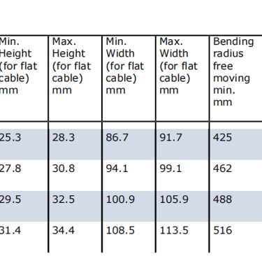
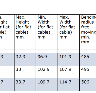
Minimum bending radius specifications follow DIN VDE 0298 Part 3 guidelines, with practical application requiring consideration of the cable profile. For flat cables, the recommended approach applies the cable diameter calculation as D = 1.5 × height of the flat cable. For free-moving fully flexible operation, the minimum bending radius typically equals 1.5 × calculated diameter.
Forced guidance systems involving reeling operations require more conservative bending radius specifications, generally 5-6 × calculated diameter depending on specific application parameters. Sheave-guided systems demand larger radii, typically 7.5 × calculated diameter, to minimize stress concentration and extend cable service life.
S-type directional changes require minimum spacing of 20 × cable diameter between change points. This spacing allows the cable to transition between direction changes without excessive stress accumulation, which could lead to premature mechanical failure or electrical insulation breakdown.
Travel Speed Limitations
Maximum travel speed for gantry reeling operations is 120 meters per minute under standard conditions. This limitation balances operational efficiency against mechanical stress accumulation. Systems operating at higher speeds require engineering evaluation to assess whether modified cable designs or installation techniques can safely accommodate the increased dynamic loading.
The flat cable profile inherently limits travel speeds compared to round cable equivalents due to higher air resistance and increased mechanical stress during rapid directional changes. However, for applications where reeling occurs predominantly in a single plane, the flat design offers superior performance through reduced tendency to twist and more predictable mechanical behavior.
Fiber-Optic Data Transmission Capabilities
Transmission Performance Parameters
The integrated fiber-optic system delivers exceptional data transmission capabilities immune to electromagnetic interference. Multimode G62.5/125 μm fibers support bandwidth of 400 MHz at 850 nm wavelength, suitable for standard industrial Ethernet protocols including 100BASE-FX and 1000BASE-SX implementations. The 600 MHz bandwidth at 1300 nm wavelength extends transmission distances for higher-speed protocols.
Enhanced G50/125 μm fibers provide 1200 MHz bandwidth at 1300 nm, supporting advanced communication protocols including 10GBASE-SR for applications requiring multi-gigabit data rates. This performance level accommodates modern crane automation systems with real-time video monitoring, advanced positioning systems, and high-speed PLC communication.
Single-mode E9/125 μm fibers enable transmission over multiple kilometers with virtually unlimited bandwidth potential. Chromatic dispersion characteristics of 3.5 ps/nm·km at standard wavelengths support coherent transmission technologies and wavelength-division multiplexing for maximum channel capacity.
Data Communication Applications
The fiber-optic integration supports diverse industrial communication requirements. Profibus, Profinet, EtherCAT, and other industrial fieldbus protocols operate reliably over the fiber-optic links, providing deterministic communication for automated material handling systems. The complete galvanic isolation eliminates ground loop problems that plague copper-based communication systems in large industrial installations.
Real-time positioning systems for automated cranes utilize the fiber-optic channels for precise location data transmission without latency or interference issues. Load monitoring systems, anti-collision technologies, and remote diagnostics all benefit from the reliable high-bandwidth communication path.

Common Cable Challenges and Solutions
Problem: Cable Damage from Improper Bending Radius
Issue Description: Operators may observe premature cable failure, conductor breakage, or fiber-optic transmission errors when cables are forced through tight curves or improper sheave installations that violate minimum bending radius specifications.
Root Cause Analysis: Excessive bending stress concentrates mechanical forces at specific points along the cable length. For conductors, this creates fatigue conditions leading to strand breakage. For fiber optics, microbending losses increase attenuation and eventually cause fiber fracture. The flat cable profile makes bending radius violations particularly problematic, as the asymmetric stress distribution accelerates damage progression.
Solution Implementation: Carefully measure all sheave diameters, roller dimensions, and guide paths during installation to verify compliance with minimum bending radius specifications. For 3x50 mm² cable with approximate 30 mm height, the calculated diameter becomes 1.5 × 30 = 45 mm, requiring minimum bending radius of 225 mm for reeling operations (5 × 45). Install appropriately sized components and, where necessary, modify installation layouts to eliminate tight curves. Regular inspection of cable path geometry prevents gradual deterioration of installation quality.
Problem: Fiber-Optic Transmission Errors During Operation
Issue Description: Intermittent communication failures, increased bit error rates, or complete loss of data transmission through fiber-optic channels during crane movement indicates potential fiber integrity problems.
Root Cause Analysis: Several mechanisms can compromise fiber-optic performance in reeling cable applications. Excessive tensile loads stretch fibers beyond their elastic limit, creating permanent microbends that increase attenuation. Torsional stress on the cable can twist fiber bundles, similarly increasing losses. Water ingress into fiber tubes creates light scattering interfaces. Installation damage during cable termination procedures can introduce sharp bends at connector points.
Solution Implementation: Verify tensile loads remain within specification throughout the operating envelope, paying particular attention to acceleration and deceleration phases where dynamic loads peak. Ensure torsional stress is minimized through proper cable attachment methods and elimination of system-induced twisting. The cable design inherently opposes torsional loads, but installation practices must not create twist accumulation. Inspect fiber-optic terminations using optical time-domain reflectometry (OTDR) to identify and localize attenuation points. Professional factory-prepared terminations significantly reduce installation-related failures compared to field termination procedures. Implement environmental protection at cable ends to prevent moisture ingress into fiber tubes.
Problem: Insulation Degradation and Electrical Tracking
Issue Description: Progressive increase in leakage current, partial discharge activity detected through monitoring systems, or eventual insulation breakdown indicates deteriorating electrical integrity of medium voltage insulation.
Root Cause Analysis: Multiple environmental and operational factors contribute to insulation aging. Sustained operation near maximum temperature limits accelerates polymer degradation through oxidation processes. Contamination of the outer sheath surface with conductive materials (metal dust, salt deposits, carbon-based contaminants) creates tracking paths that concentrate electrical stress. Mechanical damage to the outer sheath exposes inner components to moisture and contaminants. Improper cable termination procedures that damage semiconductive layers create field concentration points initiating partial discharge.
Solution Implementation: Implement routine infrared thermography surveys to identify cables operating above normal temperature ranges, which may indicate overloading or deteriorating connections. Monitor partial discharge levels using appropriate detection equipment capable of distinguishing cable-originated signals from environmental noise. Clean cable surfaces regularly in contaminated environments, removing conductive deposits before tracking paths develop. Inspect cable entries and terminations for proper environmental sealing, particularly in outdoor installations or areas with water exposure. Ensure all termination procedures follow manufacturer specifications, with particular attention to semiconductive layer preparation. The warm-removable outer semiconductive layer design simplifies proper termination, but technician training remains essential for reliable results.
Problem: Mechanical Damage During Reeling Operations
Issue Description: Visible outer sheath damage, flat spots, or localized deformation appear on cables after extended service in reeling applications, potentially compromising long-term reliability.
Root Cause Analysis: Improper reeling drum design, damaged roller surfaces, or incorrect cable guidance creates repetitive mechanical stress concentrations. Operating beyond specified travel speeds increases dynamic loading. Multiple cables reeled on the same drum without proper separation create crushing forces. Allowing cable slack during reeling permits uncontrolled movement and impact damage.
Solution Implementation: Inspect reeling drums and guide rollers regularly for surface damage, verifying smooth bearing operation and proper alignment. Maintain travel speeds within specified limits, recognizing that higher speeds increase both impact forces and wear rates. When multiple cables share a reeling drum, implement proper spacers or separate drums to prevent mechanical interference. Adjust cable tensioning systems to maintain appropriate tension throughout the operating range, preventing slack accumulation. The flat cable profile requires particular attention to drum design, as improper winding can create edge damage. Select reeling drums with widths appropriate for the cable dimensions, allowing proper layer formation without edge crowding.
Installation Best Practices and Commissioning
Cable Preparation and Termination
Fiber-optic preparation requires specialized skills, tools, and controlled environmental conditions. Factory assembly of fiber-optic terminations provides superior reliability compared to field termination procedures, as the factory environment eliminates contaminants, provides precise dimension control, and enables comprehensive testing before shipment. When ordering cables with factory terminations, provide accurate dimension specifications including cable lengths and connector positions.
Medium voltage cable termination demands careful attention to electrical field control. The warm-removable outer semiconductive layer simplifies preparation by eliminating the need for aggressive mechanical or chemical stripping methods that risk insulation damage. Remove the outer sheath to expose adequate length for stress cone installation, carefully strip the outer semiconductive layer according to termination kit instructions, and thoroughly clean all surfaces before applying stress control components.
System Testing and Validation
Comprehensive testing before energization prevents installation defects from causing operational failures. Perform insulation resistance measurements between all conductors and between each conductor and the ground system, verifying results exceed minimum acceptable values specified for the voltage rating. For 6 kV systems, insulation resistance should exceed 1000 megohms for new installations.
Apply high-potential (hi-pot) testing according to manufacturer specifications and applicable standards. AC test voltage levels are specified for each voltage rating, applied for minimum five-minute duration to verify insulation integrity. Progressive voltage application with leakage current monitoring provides additional diagnostic information about insulation quality.
Fiber-optic transmission testing using OTDR equipment identifies splice losses, connector quality, and any fiber damage along the cable length. Bidirectional testing from both ends provides complete characterization of the fiber-optic system. Bit error rate testing under full data load confirms adequate transmission quality for the specific communication protocols deployed.
Conclusion
The PROTOLON(FL)-LWL medium voltage flat reeling cable with integrated fiber-optics represents an advanced engineering solution for demanding industrial applications requiring simultaneous power transmission and data communication. The flat cable profile optimizes performance for reeling operations with predominantly single-plane directional changes, while the fiber-optic integration eliminates the need for separate communication infrastructure.
Successful deployment requires careful attention to installation specifications, particularly regarding bending radius limits, tensile load management, and environmental protection. When properly installed and maintained, these cables provide reliable long-term performance in the harsh operating environments characteristic of container terminals, mining operations, and heavy industrial facilities. The combination of robust mechanical design, sophisticated electrical insulation systems, and protected fiber-optic communication channels makes this cable type well-suited for modern automated material handling systems where reliable power delivery and high-speed data transmission are both mission-critical requirements.
How to Reach Us
Get in Touch
SiteMap
Product Catalogue
Festoon Cable
Shore Power Cable




Scan to add us on WeChat