
PVC-Flat-CY Screened Cable: VDE-Compliant Design for Industrial Trailing and Conveyor Applications
Explore the robust PVC-Flat-CY screened cable, an EMC-preferred VDE-compliant solution crafted from special PVC material, ideal for demanding trailing cable uses in crane installations, floor conveyor systems, and shelf control units, ensuring oil resistance and electromagnetic compatibility.
hongjing.Wang@Feichun
2/10/20269 min read

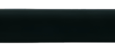
In modern industrial environments, the reliability of electrical infrastructure directly impacts operational efficiency and safety. Electromagnetic compatibility (EMC) has become a critical consideration as facilities grow increasingly dependent on sensitive electronic controls and automated systems. Screened cables play a vital role in mitigating electromagnetic interference while delivering power and signals across dynamic installations. The PVC-Flat-CY represents a specialized solution engineered specifically for demanding applications where both flexibility and electromagnetic shielding are paramount.
This screened flat cable adapts to DIN VDE 0283 part 2 standards, positioning it as an EMC-preferred choice for installations requiring consistent performance under challenging conditions. Its unique flat profile combined with comprehensive screening makes it particularly suitable for trailing cable applications in crane systems, floor conveyor installations, and shelf control units. Understanding the technical specifications, structural design, and proper installation techniques enables engineers and facility managers to maximize the performance and longevity of these cables in their specific operational contexts.
Technical Specifications: Understanding Performance Parameters
The electrical and mechanical specifications of the PVC-Flat-CY determine its suitability for various industrial applications. Temperature tolerance represents a fundamental consideration, with this cable rated for flexing operations between -5°C and +70°C. For fixed installations where the cable remains stationary, the operational range extends from -40°C to +80°C. This broad temperature window accommodates both indoor climate-controlled facilities and outdoor installations subject to seasonal variations.
From an electrical perspective, the cable carries a nominal voltage rating of U₀/U 300/500 V, making it appropriate for low-voltage industrial applications. The test voltage of 3000 V provides verification of insulation integrity during quality control, while the minimum breakdown voltage of 6000 V offers substantial safety margin against insulation failure. These voltage ratings align with common industrial power distribution requirements while maintaining compliance with safety standards.
Mechanical flexibility significantly influences installation feasibility and cable service life. The minimum bending radius specification of 15 times the cable thickness prevents insulation damage and conductor fatigue during installation and operation. This parameter becomes particularly relevant when routing cables around corners, through cable carriers, or in festoon systems where repeated flexing occurs. Engineers must account for this bending radius when designing cable paths and selecting support hardware.
The cable demonstrates radiation resistance up to 80×10⁶ cJ/kg (80 Mrad), indicating suitability for environments with moderate radiation exposure. While not designed for high-radiation nuclear applications, this specification confirms the cable can withstand sterilization processes and environments with industrial radiation sources without significant degradation.
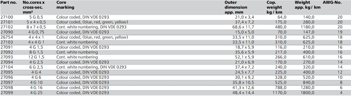
Available configurations span a wide range of conductor counts and cross-sections. Part numbers cover options from 4 conductors with 0.75 mm² cross-section up to 4 conductors at 25 mm², with multi-layer configurations available such as 8×7×0.5 mm² for complex control applications. Copper weights range from 64 kg/km for the smallest configuration to 1800 kg/km for the largest, directly impacting both cost and current-carrying capacity. Outer dimensions vary accordingly, from 15.0×5.0 mm for compact installations to 48.4×14.4 mm for heavy-duty power applications.
Cable Structure and Design: Engineering for Performance
The conductor construction employs bare copper manufactured to DIN VDE 0295 class 5 specifications, corresponding to BS 6360 class 5 and IEC 60228 class 5 standards. Class 5 designation indicates fine-wire stranding, which provides superior flexibility compared to solid or less-stranded conductors. This construction proves essential for trailing cable applications where repeated flexing would quickly fatigue solid conductors or those with larger individual wire strands.
Core insulation utilizes special PVC formulation engineered to balance flexibility, electrical insulation properties, and mechanical durability. Unlike standard PVC compounds, this specialized material maintains insulation integrity through repeated bending cycles while resisting oil contamination common in industrial environments. The insulation thickness complies with voltage rating requirements while minimizing overall cable diameter to preserve flexibility.
Core identification follows two primary systems depending on configuration. Smaller conductor counts typically employ color coding per DIN VDE 0293, using standard colors for easy identification during installation and maintenance. Configurations with higher conductor counts utilize continuous white numbering, which prevents confusion in complex multi-conductor applications where color repetition would become necessary. The "G" designation in part numbers indicates inclusion of a green-yellow protective earth conductor, while "x" configurations omit this conductor for applications where separate grounding is provided.
Screening represents a critical design element for EMC performance. Individual cores or bunched groups receive copper braiding with approximately 85% coverage. This coverage percentage balances electromagnetic shielding effectiveness with cable flexibility—higher coverage would improve shielding but reduce flexibility, while lower coverage would compromise EMC performance. The copper braiding must achieve large round contact areas at both cable ends to optimize screening effectiveness, as point contacts create high-resistance paths that degrade shielding performance.
The outer sheath employs special PVC formulation in black (RAL 9005), providing mechanical protection against abrasion, chemical exposure, and environmental factors. The flat profile of this sheath distinguishes these cables from round alternatives, offering advantages in specific installation configurations while introducing unique handling requirements.
Key Properties and Performance Tests: Ensuring Reliability
Oil resistance constitutes a significant property for industrial applications where cables encounter lubricants, hydraulic fluids, and cutting oils. The special PVC compound demonstrates extensive oil resistance, preventing insulation swelling and degradation that would compromise electrical integrity. This characteristic proves particularly valuable in manufacturing facilities, metalworking shops, and automated material handling systems where oil contamination is unavoidable.
Fire safety performance meets stringent requirements through self-extinguishing and flame-retardant properties verified per DIN VDE 0482-332-1-2, DIN EN 60332-1-2, and IEC 60332-1 standards (equivalent to DIN VDE 0472 part 804 test method B). When exposed to ignition sources, the cable insulation and sheath resist sustained burning, extinguishing themselves once the ignition source is removed. This behavior prevents cables from becoming fire propagation paths, a critical safety consideration in facilities where ignition sources may occur.
Electromagnetic compatibility features stem from the comprehensive screening design. The copper braiding intercepts electromagnetic fields generated by conductors and external sources, routing interference currents to ground rather than allowing them to couple into adjacent circuits. For optimal EMC performance, installation practices must ensure the copper braiding achieves continuous electrical connection to ground through large contact surfaces at termination points. Small or corroded contact areas create resistance that degrades screening effectiveness, potentially allowing interference to reach sensitive control circuits.
The cable conforms to EC Low-Voltage Directive 2006/95/EC, demonstrating compliance with European safety requirements for electrical equipment. This certification provides assurance that design, materials, and manufacturing processes meet harmonized safety standards, simplifying specification for projects requiring regulatory compliance documentation.
AWG size listings provide approximate equivalents to metric cross-sections, facilitating specification when working with equipment designed to American wire gauge standards. However, the actual conductor cross-sections remain in mm², and users must verify that AWG equivalents meet current-carrying requirements for their specific applications.
Applications and Use Cases: Where These Cables Excel
Crane installations represent a primary application where PVC-Flat-CY cables deliver significant advantages. Mobile cranes, overhead traveling cranes, and gantry cranes require power and control cables that travel with moving components while resisting the harsh conditions typical of industrial facilities. The flat profile allows efficient packing of multiple cables in festoon systems or cable carriers, reducing the space envelope required for cable management. Screening prevents electromagnetic interference from crane motor drives from disrupting control signals, ensuring precise and safe operation.
Floor conveyor systems benefit similarly from the cable's combination of flexibility and durability. Conveyors in distribution centers, manufacturing facilities, and logistics operations move constantly, subjecting cables to continuous flexing. The fine-wire conductor construction withstands this repetitive motion far better than cables with larger strand diameters. Oil resistance proves essential in these environments where conveyor lubrication and product spillage regularly contaminate cable routes.
Shelf control units in automated storage and retrieval systems (AS/RS) exemplify another ideal application. These systems require cables that flex as shelving units move vertically and horizontally to access storage locations. The flat cable profile allows efficient routing through confined spaces between shelf structures, while screening prevents interference between control signals managing multiple shelf units operating in proximity.
Dynamic industrial environments present unique challenges that these cables address effectively. The flexibility on plane surfaces allows the cable to bend smoothly in one direction while maintaining relatively rigid profile in the perpendicular direction. This anisotropic flexibility suits cable carrier applications where cables must flex repeatedly in one plane while remaining stable in the other axis to prevent twisting and tangling.
However, applications involving multicore flat cables with small cross-sections below 2.5 mm² require special consideration. The low tensile strength of these configurations makes them vulnerable to mechanical damage if subjected to excessive pulling forces during installation or operation. Engineers should incorporate 10% reserve wire capacity in calculations to account for this limitation, either by selecting the next larger cross-section or limiting the mechanical loads applied to the cable. This precaution prevents conductor breakage that could result in system failures and costly downtime.
Installation Guidelines: Proper Techniques for Long Service Life
Transportation and storage practices significantly influence cable condition before installation even begins. Cable reels containing flat cables must be transported in standing position resting on the flange rather than lying on the cylindrical reel body. This orientation prevents the cable's flat profile from becoming deformed under the weight of the reel, which could introduce permanent bends or kinks that compromise flexibility and create stress points.
Achieving optimal bending flexibility requires installation on plane surfaces rather than attempting to force the cable into compound bends. The cable's flat profile naturally flexes in one direction; attempting to bend it in multiple planes simultaneously induces excessive stress that can damage insulation and fatigue conductors. Following manufacturer fitting instructions ensures proper routing that accommodates the cable's mechanical characteristics.
Cable trolley installation begins with positioning units on guiding rails or carrier beams. The critical spacing parameter requires that the distance between bedding surfaces of adjacent trolleys exceeds twice the thickness of the complete cable packet. Insufficient spacing creates pinch points where cables experience excessive compression, leading to insulation damage and potential conductor failure. Adequate spacing allows cables to form smooth catenary curves between support points, distributing mechanical stress evenly.
Packet assembly sequence directly affects load distribution and mechanical stress. Installation must start with the smallest cross-section cable positioned on the bedding surface, building successive layers so the largest cross-section occupies the top position. This arrangement places lighter cables where they receive support from below while heavier cables utilize gravity to maintain stable positioning. Reversing this sequence concentrates stress on smaller conductors that lack the mechanical strength to support heavier cables above them.
Symmetrical load distribution across the cable packet prevents uneven stress that could cause cables to shift during operation. Distributing cables evenly from side to side and along the length of the installation minimizes localized stress concentrations. Asymmetrical loading creates unbalanced forces that can cause cables to twist or migrate, potentially leading to pinching, abrasion, or excessive bending at support points.
Common Cable Issues and Solutions
Problem: Electromagnetic interference affecting control signals despite cable screening
This issue typically results from improper screen termination. The copper braiding requires large round contact areas at both cable ends to provide low-resistance paths for interference currents. Small contact areas or connections degraded by corrosion create resistance that limits screening effectiveness. Solution: Ensure screen terminations use dedicated screen connectors with substantial contact surface area. Clean contact surfaces thoroughly before termination and apply contact protection compounds to prevent corrosion in humid environments.
Problem: Premature cable failure in high-flex applications
When cables fail sooner than expected service life predictions, installation bending radius often exceeds specifications. Solution: Verify that all cable routing maintains minimum bending radius of 15 times cable thickness. Measure actual bending radii at support points and route transitions. Redesign cable paths that violate this parameter, potentially adding intermediate support points or modifying support hardware geometry.
Problem: Insulation cracking in outdoor installations
Temperature extremes beyond the cable's rated range accelerate insulation aging. Solution: Verify ambient temperatures remain within -40°C to +80°C for fixed installations or -5°C to +70°C for flexing applications. If environmental conditions exceed these ranges, consider supplemental environmental protection such as conduit systems or heated/cooled cable enclosures.
Problem: Conductor breakage in cables with cross-sections below 2.5 mm²
Fine conductors in multicore configurations possess limited tensile strength. Solution: Implement the recommended 10% reserve wire practice by selecting the next larger cross-section or reducing mechanical loads. Install strain relief devices that transfer pulling forces to the cable sheath rather than conductors. Limit cable run lengths to reduce weight-induced tension.
Conclusion
The PVC-Flat-CY screened cable delivers a purpose-engineered solution for industrial applications demanding reliable performance under challenging conditions. Its combination of fine-wire copper conductors, specialized PVC insulation and sheathing, comprehensive electromagnetic screening, and flat profile addresses the specific requirements of trailing cable installations in crane systems, floor conveyors, and shelf control units. Compliance with DIN VDE standards and EC directives ensures the cable meets recognized safety and performance requirements.
Successful implementation requires understanding both the cable's capabilities and its limitations. The broad temperature range, oil resistance, and flame-retardant properties enable operation in diverse industrial environments. However, proper installation practices—including correct bending radius, symmetrical load distribution, and appropriate screen termination—prove essential to achieving design service life. Special attention to applications involving small cross-section conductors prevents premature failures related to mechanical stress.
For engineers and facility managers specifying cables for new installations or replacement projects, the PVC-Flat-CY warrants consideration wherever EMC performance, flexibility, and VDE compliance align with project requirements. Consulting detailed specifications for specific part numbers ensures selection of configurations matching conductor count, cross-section, and dimensional constraints of the intended application. By matching cable characteristics to application demands and following proper installation procedures, facilities can achieve reliable electrical infrastructure supporting efficient industrial operations.
How to Reach Us
Get in Touch
SiteMap
Product Catalogue
Festoon Cable
Shore Power Cable




Scan to add us on WeChat