
Reeling Cable for Automated Stacking Cranes: Engineering Requirements, Motion Stress, and Failure Risks in AS/RS Systems
How reeling cables survive high-speed, high-cycle stress in AS/RS systems up to 300 m/min. Covering motion stress, failure risks, cable types, and Australian port applications.
hongjing.Wang@Feichun
6/10/202621 min read
Introduction: Why Reeling Cables Are Critical in Automated Stacking Crane Systems
Walk into a modern high-bay warehouse or a semi-automated container terminal and the first thing that strikes you is the silence. There's no shouting, no diesel haze, no forklifts darting between aisles. Instead, towering stacker cranes glide through narrow corridors at speed, pulling and placing pallets or containers with a precision that borders on uncanny. It looks effortless. It looks like the machines simply know what to do. But behind that smooth choreography sits a network of components working under enormous and relentless stress — and one of the most overlooked of them is the humble reeling cable.
Automated Storage and Retrieval Systems, or AS/RS, live and die by uninterrupted high-speed material flow. The whole economic case for automating a warehouse or a container yard rests on throughput: more moves per hour, fewer errors, less labour, around the clock. That throughput depends on the stacker crane being able to move continuously, and the stacker crane can only move continuously if it has power and control signals delivered reliably to a structure that is, by definition, in constant motion. That's the reeling cable's job. It is the lifeline between the stationary power supply and the moving crane — the single physical link carrying the electricity and the data that keep the whole system alive.
And here's the uncomfortable truth that every terminal engineer and warehouse maintenance manager learns sooner or later: when that cable fails, everything stops. There's no graceful degradation, no limping along at reduced capacity. A reeling cable failure directly halts warehouse automation and triggers system-wide downtime. The crane sits dead in the aisle. The retrieval queue backs up. In a container terminal, ships wait and demurrage clocks start ticking. The cable that nobody thought much about during procurement suddenly becomes the most important — and most expensive — component in the building.
The problem is getting harder, not easier. AS/RS systems keep getting faster, the cycle frequencies keep climbing, and the intelligence layered on top keeps demanding more data throughput. Every one of those trends piles more mechanical stress onto the reeling cable. Higher speeds mean more abrasion and more violent acceleration. Higher cycle counts mean more fatigue. Smarter systems mean more conductors and fibres crammed into a cable that still has to flex millions of times without complaint. It all distils down to one core engineering equation that anyone specifying these systems needs to have tattooed on the back of their hand:
High-Speed + High-Cycle Fatigue = Cable Failure Risk.
This article unpacks that equation in detail. We'll walk through the architecture of AS/RS systems and where the reeling cable fits, examine the reeling mechanism that handles the cable, break down the specific motion stresses the cable endures, survey the cable types and the manufacturers behind them — including the gear actually running at Australian ports and mines — and then drill into the failure mechanisms and the engineering strategies that extend cable life. Along the way, we'll be honest about where the gaps in the market sit and where there's genuine room to do better. Let's get into it.
AS/RS System Architecture and Role of Reeling Cables
To understand why the reeling cable matters so much, you first need to understand the system it serves. A reeling cable doesn't operate in isolation — it's one component in a tightly integrated automation system, and its demands are dictated entirely by the behaviour of everything around it.
Overview of Automated Storage and Retrieval Systems
An AS/RS is not a single machine but an orchestrated system of several subsystems working in concert. At its core it integrates stacker cranes, warehouse racking systems, conveyor systems, and centralised control systems built on PLC and WCS architecture. Each of these has a distinct role, and the whole thing only works when they communicate flawlessly in real time.
The workflow itself is worth picturing because it explains where the stress comes from. It begins when a command arrives from the warehouse control system — the WCS — telling the system to store or retrieve a particular item. The stacker crane then needs to know exactly where it is and where it's going, which it achieves through real-time positioning using laser measurement and an array of sensors. Motion is coordinated across multiple axes via the PLC and frequency converters, which translate the high-level command into precise movements of the crane's drive systems. Throughout all of this, distributed sensors feed continuous position and status data back to the controller, allowing constant correction and refinement. The result is fully automated storage and retrieval in high-bay warehouses that can reach tens of metres in height — racking so tall that no human-operated machine could safely or efficiently service it.
What this means for the cable is that every command, every positional correction, every sensor reading either travels through the reeling cable or depends on power that does. The cable isn't a passive bystander to the automation — it's woven into the control loop.
Stacker Crane Structure in AS/RS Systems
The stacker crane is the moving heart of the system, and it comes in two main structural forms. The single-column stacker crane is the simpler and lighter option, well suited to lower-duty applications where weight and cost are the primary concerns. The double-column stacker crane, by contrast, is more stable, suffers less vibration, and is better suited to high-cycle operation — which is exactly why it tends to dominate in the most demanding, highest-throughput installations. That reduced vibration matters for the cable too, because vibration translates into additional micro-movements that accelerate fatigue.
The crane's core function is motion control across the X, Y, and Z axes: horizontal travel along the aisle, vertical travel up the mast, and the depth movement needed to place or retrieve a load. In high-bay warehouses the horizontal travel happens at high speed through narrow aisles, which leaves no margin for error in positioning. Precise positioning for automated pallet handling is non-negotiable, because the crane has to insert and extract loads from racking with clearances measured in centimetres.
Coordinating all of this is a control system that functions almost like a nervous system. The PLC acts as the brain, making the decisions and issuing the commands. The servo and frequency drive systems act as the motion execution units, the muscles that actually move the crane. And the sensors provide real-time position feedback, the senses that tell the brain where everything is. Every part of this depends on signals and power moving cleanly through the cabling — and on the moving crane, that means the reeling cable.
Role of Reeling Cable in System Energy and Data Transfer
So we arrive at the cable itself. The reeling cable connects the stationary power supply to the moving crane system, and it carries three things: power transmission to drive the motors and systems, control signal transmission to coordinate motion, and — increasingly — optional data and fibre communication for the high-bandwidth feedback that intelligent systems require.
What makes this genuinely difficult is that the cable has to do all of this while in continuous motion. It operates under constant dynamic bending as it wraps onto and off the reel, under acceleration and deceleration forces as the crane speeds up and slows down, and under torsional stress as the reeling action twists the cable structure. It is, in effect, a power-and-data umbilical that never gets to rest.
And the consequence of failure bears repeating because it drives every design decision downstream: any failure of the reeling cable leads to immediate system downtime in AS/RS operations. There's no redundancy in most installations — one cable, one lifeline. That single point of dependency is precisely why the engineering of this component deserves far more attention than it typically gets at the procurement stage.
Reeling System Engineering and Cable Handling Mechanism
The cable doesn't manage itself. Around it sits an entire mechanical system whose job is to store, release, guide, and protect the cable as the crane moves. Understanding this mechanism is essential, because many cable failures are actually failures of the interaction between the cable and the handling system — not the cable alone.
Cable Drum and Reel System Architecture
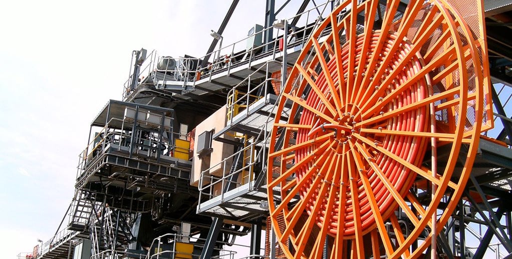
The reeling system is a coordinated assembly of several elements. At its centre is the cable drum, the reel body onto which the cable is wound and from which it pays out. Feeding the cable cleanly onto the drum is the guiding funnel system, which directs the cable to the correct position as it winds. Roller and deflection mechanisms manage the cable's path and absorb directional changes, while anchoring and connection interfaces secure the cable's ends and provide the electrical terminations. Surrounding all of this are protective cable routing structures that shield the cable from the environment and from mechanical contact.
The functions of this assembly are threefold. First, it stores and releases cable during crane movement, paying out length as the crane travels away from the feed point and reeling it back in as the crane returns. Second, it maintains controlled tension — too little and the cable sags and tangles, too much and it overstresses the conductors. Third, it prevents entanglement and mechanical damage, keeping the cable from snagging, crushing, or abrading against the structure. The entire assembly is designed for high-speed automated environments with demanding dynamic motion requirements, which is to say it has to do all of this perfectly, thousands of times a day, for years.
Operating Conditions in Modern AS/RS Systems
The numbers involved put the challenge into perspective. Voltage ranges typically run from 3 kV up to 36 kV, spanning low-voltage control systems through to the medium-voltage power feeds used on larger cranes and bulk handling equipment. Operating speeds range from 120 m/min up to 300 m/min, and these systems are designed for continuous automated operation with minimal maintenance interruption. That last point is the killer requirement. It's one thing to build a cable that survives high speed; it's another to build one that survives high speed continuously, with the expectation that it won't need to be touched for years. The maintenance window in a fully automated facility is small and expensive, so every component is expected to simply keep working. For the reeling cable, that expectation is brutal.
Cable Motion Stress Parameters in Stacker Crane Applications
This is the heart of the engineering problem. To specify a reeling cable correctly you have to understand precisely how it's being stressed, because each type of stress attacks the cable in a different way and demands a different design response. Let's take them one at a time.
High-Speed Reeling Conditions
Speed is the headline stressor. Horizontal crane travel speed can reach up to 180 m/min in typical high-performance installations, while spreader and platform speeds sit around 60 m/min. In the most extreme applications, high-performance systems may reach 300 m/min — a figure that comes up repeatedly in the specifications for the fastest automated container terminals. To put that in perspective, at 300 m/min the cable is being reeled at five metres every second, every winding and unwinding cycle imposing fresh stress on the structure.
High-speed motion significantly increases both abrasion and internal stress accumulation. The faster the cable moves, the more violently it interacts with the guide rollers, the funnel, and the drum surface, and the more rapidly the abrasive wear builds up on the jacket. Internally, the higher speeds mean the conductors and fillers experience more aggressive relative movement, and that movement is the seed of long-term fatigue damage. Speed, in short, multiplies every other stress.
Acceleration and Deceleration Stress
It isn't just sustained speed that matters — it's how the cable gets up to that speed and back down again. Typical stacker crane acceleration sits around 0.5 m/s², and in a high-throughput operation the crane is constantly starting and stopping as it moves between racking locations. Those frequent start-stop cycles generate repetitive mechanical fatigue, each acceleration and deceleration sending a stress pulse through the cable.
High-acceleration environments amplify the internal movement of the conductors. When the crane lurches into motion or brakes hard, the mass of the cable and its internal components wants to keep doing what it was doing, and that inertia drives the conductors to shift relative to one another inside the jacket. Over time, the cumulative effect is progressive micro-damage accumulation — tiny instances of damage that individually mean nothing but collectively march the cable toward failure. This is why a cable that performs beautifully in a steady-state test can still fail prematurely in a real installation with thousands of acceleration cycles a day.
Bending Radius and Mechanical Fatigue
Every time the cable wraps onto the drum, it bends. The bending radius — how tightly it has to curve — is one of the most consequential parameters in the entire system. A smaller bending radius improves flexibility and allows for a more compact reeling system, but it also increases fatigue concentration if the cable isn't properly designed for it. Bend a cable too tightly and the outer conductors are stretched while the inner ones are compressed, concentrating stress at the bend point.
This is one area where cable geometry makes a real difference. Flat cables typically achieve a tighter bending radius than round cables, because their flat profile distributes the bending stress more evenly across the conductors rather than concentrating it. Regardless of geometry, though, repeated bending cycles are a primary cause of two of the most common failures: jacket cracking and conductor breakage. The jacket cracks because the polymer fatigues at the bend; the conductors break because the copper strands fatigue from the repeated flexing. Get the bending radius wrong, and you've designed failure into the system from day one.
Torsion Effects in High-Speed Reeling
Torsion is the stress that catches people out, because it's harder to visualise than simple bending. High-speed reel systems generate internal torsional stress — the cable doesn't just bend as it winds onto the drum, it also twists. And twist is particularly destructive because it acts on the cable's internal structure in a way that simple bending doesn't.
When a cable has a poor internal structure, that torsional stress causes internal conductor displacement. The conductors shift and migrate within the jacket, and over time that displacement leads directly to conductor breakage. This is exactly the failure mode that the best reeling cable designs are engineered to prevent. Advanced cable designs lock the internal structure against relative movement, so that when the cable is twisted, the conductors stay put rather than wandering. Without effective torsion control, conductor breakage becomes highly likely at high reeling speeds — and at 300 m/min, the consequences of a conductor letting go can be both expensive and dangerous. This is precisely the problem that purpose-built high-speed reeling cables are designed to solve, and it's worth understanding when comparing one cable against another.
Fleet Angle Misalignment Risk
Finally, there's a parameter that lives at the intersection of cable and installation: the fleet angle. The fleet angle is the angle at which the cable approaches the drum as it winds on, and getting it wrong is one of the most common installation errors in the entire reeling system. It's also one of the most underestimated, precisely because it's an installation parameter rather than a cable property, so it falls between the cracks of responsibility.
When the fleet angle is improper, the cable winds unevenly onto the drum. Instead of laying down in neat, ordered layers, it piles up in some places and gaps in others. That uneven winding causes localised stress concentration, where particular sections of cable take far more load than they should, and that concentration leads to premature jacket failure at those points. A cable that would have lasted for years can fail in months simply because the fleet angle was off by a few degrees. It's a critical design parameter that deserves careful attention during commissioning, yet it's routinely overlooked because the cable looks like it's working fine — right up until the moment it isn't.
Cable Types Used in Automated Stacking Crane Systems
Not all reeling cables are the same, and choosing the right type for the application is a foundational decision. Each type represents a different set of trade-offs between flexibility, structural integrity, capability, and cost.
Flat Reeling Cables
Flat reeling cables are purpose-built for high-flex repetitive motion systems. As discussed above, their flat profile gives them better bending performance compared to round cables, because the conductors are arranged side by side and the bending stress is distributed more evenly across the structure. This makes them well suited to cranes, elevators, and moving machinery systems where the cable is bent repeatedly in a single plane.
Beyond their bending performance, flat cables offer practical advantages. They provide space efficiency, packing neatly into reeling systems, and they deliver improved winding alignment, laying down more predictably on the drum than round cables. These qualities make them widely used in long-travel crane applications, where the combination of high flex life and clean winding is exactly what's needed.
Round Reeling Cables
Round reeling cables remain the common choice in mono-spiral reel systems, where the cable winds in a single helical layer. Their great strength is structural integrity: the bundled conductor design, with conductors arranged around a central axis, gives the cable robust mechanical strength and good resistance to crushing and impact. That makes them dependable in applications where the cable might take knocks.
The trade-off is that round cables are less optimised for tight bending environments than flat cables. The circular geometry means the conductors on the outside of a bend travel further than those on the inside, concentrating stress in a way that flat cables avoid. As a result, round reeling cables are best suited to standard crane power transmission systems where the bending demands are moderate rather than extreme.
Fibre Optic Integrated Reeling Cables
As AS/RS systems get smarter, the demand for data bandwidth grows, and that's driven the rise of fibre optic integrated reeling cables. These cables combine power transmission with fibre communication in a single structure, allowing real-time data transmission alongside the electrical supply. This is what enables the high-fidelity feedback that intelligent automation depends on — high-resolution position data, condition monitoring signals, vision system feeds, and more.
The payoff is improved operational monitoring and a genuine increase in system intelligence. By carrying fibre, the cable lets the control system see far more of what's happening on the moving crane, in real time. Example systems include high-speed crane cables designed specifically for harsh environments, where the fibre has to survive the same brutal flex, abrasion, and torsion as the power conductors. Integrating fragile glass fibre into a cable that flexes millions of times is a serious engineering achievement, and it's one of the areas where the gap between an ordinary cable and a truly well-designed one is most stark.
Power + Control Hybrid Cables
The logical extension of integration is the power-plus-control hybrid cable, which integrates power, control, and data into a single cable structure. Rather than running separate cables for each function — each needing its own reeling provision and its own routing — a hybrid cable consolidates everything into one.
The benefits are substantial. Hybrid cables reduce installation complexity and space requirements, because there's one cable to manage instead of three or four. They improve system modularity and significantly reduce wiring cost, simplifying both the initial build and ongoing maintenance. And the best of these designs are extraordinarily durable: some advanced hybrid cables support up to 10 million bending cycles, a figure that speaks to just how far the engineering has come. That kind of fatigue life is exactly what makes them highly suitable for modern AS/RS automation systems, where the cable is expected to flex relentlessly for years without intervention. When you see a number like 10 million cycles on a specification sheet, that's the manufacturer telling you they've solved the internal-movement problem that destroys lesser cables.
Industry Equipment and System Manufacturers
It helps to know who actually builds and supplies this gear, both on the system side and the cable side. The landscape includes global automation giants and specialist cable manufacturers, and — relevant to readers here — a good deal of their work is on display at Australian ports and mines.
Daifuku AS/RS Systems
Daifuku is one of the major names in automated storage and retrieval, providing automated pallet storage and retrieval systems across a wide range of industries. The company supports customised stacker crane configurations, tailoring its systems to the specific needs of each warehouse rather than forcing a one-size-fits-all approach. Its focus is on intralogistics optimisation and warehouse automation, and its systems are widely used in high-density storage environments where maximising the use of vertical space is paramount.
Dematic AS/RS Solutions
Dematic is a global supplier of automated warehouse systems and a familiar name across the logistics sector. It provides integrated stacker crane and warehouse automation solutions, bringing the cranes, racking, software, and controls together as a coherent package. Its emphasis sits on high-efficiency logistics system design — squeezing maximum throughput and reliability out of the automated warehouse — which makes it a common choice for large-scale distribution operations.
KUKA Logistics Systems
Better known to many for its industrial robots, KUKA also provides robotic automation and warehouse logistics systems. It supports stacker crane integration within smart factory environments, where the warehouse automation has to mesh seamlessly with manufacturing and robotic processes. Its focus on intelligent automation and precision control reflects the broader trend toward warehouses that aren't just automated but genuinely smart, coordinating storage with production in real time.
Industrial Cable System Suppliers
On the cable and reeling side, a handful of specialists dominate, and their footprint in Australia is significant. Cavotec provides motorised cable reel systems for port and crane applications, and its presence in the Australian market is substantial. In a recent example, Cavotec signed a contract with Australian engineering company Civmec to supply a motorised cable reel for installation at Port Hedland in Western Australia — one of the world's largest iron ore export facilities — with delivery scheduled for the third quarter of 2026. Cavotec's track record extends across Australian bulk handling, including reeling solutions for stacker-reclaimers in the surface mining sector.
Conductix-Wampfler specialises in dynamic energy and data transmission systems for automated cranes, supplying cable and hose reels, festoon systems, energy guiding chains, and slip rings for mining and port applications. In the Australian mining context, the company supplies motor-driven reeling systems and slip-ring assemblies rated for the high currents and voltages used in circular stacker-reclaimers, enabling continuous rotation while maintaining reliable power and data transfer.
Konecranes integrates advanced crane system components and cable solutions across its industrial and port equipment, and it's one of the most visible crane brands in Australia. Konecranes has delivered over 250 container cranes equipped with cable reels worldwide, and in Australia its equipment runs at major facilities — for instance, Pilbara Ports ordered two Konecranes Gottwald mobile harbour cranes for the Port of Port Hedland, equipped with 100-metre cable reels for external power supply, with delivery in 2026. Konecranes automated stacking cranes also feature in Australian container terminals.
Tratos Group develops high-performance reeling cables designed specifically for extreme high-speed environments, and its products are a good illustration of what purpose-built high-speed reeling cable looks like. The company's Tratosflex-ESDB range of medium-voltage rubber-insulated and sheathed drum reeling cables is engineered for high-speed reeling and is regularly incorporated into Konecranes automated stacking cranes worldwide. The design uses a tightened internal structure that resists relative movement, preventing the cable from twisting and breaking when reeling at speeds up to 300 m/min — the exact torsion problem described earlier. These cables are specified by Konecranes for Hutchison Port Holdings container terminals in Australia, and Tratosflex is already in service in Konecranes automated stacking cranes at Hutchison's Port Botany terminal in Sydney, one of Australia's premier international container ports. The same family of cable can operate across a temperature range from around -60°C to +90°C, reflecting the extreme conditions these products are built to survive.
What This Tells Us About the Australian Market — and Where the Opportunity Sits
Step back and look at the Australian picture and a clear pattern emerges. At the major container terminals — Port Botany in Sydney, the Port of Brisbane, the Port of Melbourne, Fremantle — automation is the norm, not the exception. DP World Brisbane runs a fleet of remotely operated automated stacking cranes; Patrick Terminals runs extensive Kalmar automated equipment across Brisbane, Sydney, and Melbourne; VICT at the Port of Melbourne operates a large fleet of Kalmar automatic stacking cranes. At the bulk export end, the Pilbara iron ore operations and the Bowen Basin coalfields run stacker-reclaimers, shiploaders, and reeling drums under some of the harshest conditions on the planet, with brands like Konecranes, Cavotec, and Conductix-Wampfler supplying the hardware.
Every one of those machines depends on reeling cable, and the cable running through most of the premium installations comes from a small group of specialist suppliers charging premium prices — Tratosflex-ESDB being the archetype. That concentration is exactly where the commercial opportunity lies. These are proven, well-understood cable designs solving well-understood problems: torsion control, high flex life, abrasion resistance, wide temperature tolerance, medium-voltage capability up to 300 m/min. The engineering principles behind them are not secret. For an Australian operator facing 900-kilometre lead times to the nearest warehouse and premium pricing on imported cable, there is a genuine, demonstrable case for a high-performance alternative that matches the proven specifications — the tightened internal structure that prevents twisting, the abrasion-resistant sheath, the high-cycle fatigue rating — while shortening supply lines and easing the procurement burden. The point isn't to reinvent the reeling cable. It's to deliver the same field-proven performance, validated against the same demands these terminals and mines already specify, as a directly comparable substitute. When a single failed cable can shut down a crane handling thousands of containers a day, the value of a reliable, readily available, performance-matched alternative is easy to quantify.
Failure Mechanism in High-Speed Reeling Cable Systems
We've described the stresses individually. Now let's see how they combine to destroy a cable, because understanding the failure mechanism is what lets you design against it.
Core Engineering Principle
It all comes back to the equation introduced at the start. High-speed automated crane systems operate under one fundamental risk relationship:
High-Speed + High-Cycle Fatigue = Cable Failure Risk.
Neither factor is dangerous alone. A cable can handle high speed in short bursts, and a cable can handle millions of gentle cycles. It's the combination — high speed sustained over millions of cycles — that turns the reeling cable into the system's most vulnerable component. Every design decision, every material choice, every installation parameter is ultimately an attempt to manage this equation.
Main Failure Drivers
Several specific factors drive cables toward failure, and in a real installation they typically act together rather than in isolation. Continuous high-speed motion of up to 300 m/min imposes constant abrasion and internal stress. Frequent acceleration and deceleration cycles hammer the cable with repeated inertial loading. Improper bending radius selection concentrates fatigue stress at the bend points. Torsional stress accumulates during reeling, displacing conductors in poorly structured cables. Fleet angle misalignment in the reel system creates localised overloading. And underlying all of it, long-term fatigue from millions of motion cycles slowly erodes the cable's integrity. The danger is in the compounding: a slightly-too-tight bending radius is survivable, and a slightly-off fleet angle is survivable, but combine them with high speed and millions of cycles and the failure date moves forward dramatically.
Typical Lifecycle Failure Pattern
Failures rarely happen all at once. Instead, they follow a recognisable progression that, if you know what to look for, gives warning before the catastrophic end. It starts with initial micro-cracks in the cable jacket, forming at the points of highest stress and far too small to see in a routine inspection. Those cracks open the door to progressive insulation degradation, as moisture, contaminants, and continued flexing attack the now-exposed insulation. Next comes conductor fatigue and internal breakage, as the copper strands — stressed by bending, acceleration, and torsion — begin to fracture. As conductors degrade and break, the system experiences signal instability in the control systems, with intermittent faults that can be maddeningly hard to diagnose. And finally there is complete system shutdown due to total cable failure, the point at which the cable can no longer carry power or signal and the crane stops dead. The tragedy of this progression is that it's entirely predictable — and largely preventable, either through better cable design that resists the early stages, or through condition monitoring that catches the degradation before it reaches the end.
Engineering Strategies for Improving Cable Lifetime
If the failure mechanisms are understood, then so are the defences. Extending reeling cable life is a matter of attacking the problem on several fronts at once: the cable itself, the mechanical system around it, the materials, and the integration with the broader control system.
Use of High-Performance Cable Structures
The first and most direct lever is the cable. Selecting cables specifically designed for high-cycle fatigue resistance — rather than generic flexible cables pressed into reeling service — is the single most important decision. These are the cables with tightened internal structures, optimised conductor stranding, and fatigue ratings stated in the millions of cycles. Where the application demands it, there's a strong case for hybrid power-plus-data cable systems that consolidate functions and reduce the number of vulnerable cables, and for fibre-integrated communication cables in smart AS/RS systems where data bandwidth is critical. Choosing the right structure up front is far cheaper than dealing with the consequences of the wrong one.
Mechanical Design Optimisation
The cable can only perform if the system around it lets it. Correct fleet angle configuration is essential — getting this right at commissioning eliminates one of the most common causes of premature failure for almost no cost. Proper bending radius control ensures the cable is never bent more tightly than its design allows, preserving its fatigue life. Optimised reel tension management keeps the cable under the right tension throughout its travel, neither sagging nor overstressed. And reducing torsional stress through structural cable design — choosing a cable engineered to resist twist — closes off the torsion failure mode at its source. These mechanical measures cost little and pay back enormously.
Material Selection Strategy
Material choice tailors the cable to its specific environment. PUR or TPU jackets are the go-to for high-abrasion environments, offering the abrasion resistance and flex life that punishing reeling applications demand. Oil-resistant materials are essential for industrial warehouses and especially for mining and bulk handling environments where hydraulic oil and grease contact is unavoidable. And UV-resistant materials are necessary for exposed outdoor installations — a particularly important consideration in Australia, where the intensity of the sun at an exposed Pilbara shiploader or an outdoor container yard will rapidly degrade any jacket not properly stabilised against it. Matching the material to the real environment, rather than to a generic specification, is what separates a cable that lasts from one that fails early.
System-Level Design Approach
The most sophisticated strategy treats the cable not as a component bought at the end of the design process but as an integral part of the system designed from the start. Cable performance must be designed together with the crane motion system, so that the acceleration profiles, speeds, and reeling geometry are chosen with the cable's limits in mind rather than imposed upon it. Integrating PLC control and motion feedback can actively reduce mechanical stress — for example, by smoothing acceleration profiles to ease the inertial loading on the cable. And predictive maintenance based on cable condition monitoring catches the degradation progression early, replacing the cable on a planned basis before it fails catastrophically in service. This system-level thinking is the mark of a mature automation operation, and it's where the biggest gains in reliability and lifecycle cost are found.
Conclusion
The reeling cable in an automated stacking crane system is not a passive component. It is a dynamic mechanical system in its own right, operating under continuous and extreme stress — high speed, relentless cycling, bending, acceleration, and torsion, all at once, for years on end. Its performance directly determines the efficiency, the uptime, and the operational cost of the entire AS/RS, because when it fails, everything it serves fails with it. There is no more pointed illustration of how a small, overlooked component can hold an entire multi-million-dollar operation hostage.
Getting it right comes down to respecting the core equation — High-Speed plus High-Cycle Fatigue equals Cable Failure Risk — and managing it deliberately through proper cable design, correct mechanical configuration, appropriate material selection, and genuine system-level integration. The terminals and mines that do this well, from Port Botany to the Pilbara, run their automation reliably year after year. Those that treat the cable as an afterthought pay for it in downtime, emergency procurement, and lost throughput.
Expert Summary
If there's one piece of hard-won wisdom worth leaving you with, it's this: in high-speed reeling applications, the cable is almost always the canary in the coal mine for the health of the whole motion system. When reeling cables start failing early, the root cause is rarely the cable in isolation — it's a mismatch between the cable and the demands placed on it, whether that's an aggressive acceleration profile, a fleet angle nobody checked at commissioning, a bending radius pushed too tight to save space, or a material chosen for price rather than environment. Every one of the failure modes in this article is preventable, and the prevention is almost always cheaper than the failure.
The pattern across the field is consistent. The installations that achieve long cable life are the ones that specify against proven high-performance benchmarks — the kind of torsion-resistant, abrasion-resistant, high-cycle designs already running in Australia's most demanding ports and mines — and then back that specification with correct installation and condition-based maintenance. The good news for Australian operators is that these benchmarks are well established and the engineering behind them is well understood, which means there is real room for performance-matched alternatives that deliver the same field-proven reliability with shorter supply lines and a lower total cost of ownership. The reeling cable will never be the glamorous part of an automation project. But specify it as carefully as you specify the crane itself, and it will quietly keep your system running — which, in the end, is the only thing that matters. Treat it as the critical engineering decision it actually is, and it repays the attention many times over.
How to Reach Us
Get in Touch
SiteMap
Product Catalogue
Festoon Cable
Shore Power Cable




Scan to add us on WeChat