
SHD-GC Three-Conductor Round Portable Power Cable with CPE Jacket: 8kV Heavy-Duty Mining and Industrial Power Distribution Solution
Heavy-duty SHD-GC portable power cable with 8kV rating, CPE jacket, and reinforced construction. Ideal for longwall shearers, continuous miners, and mobile mining equipment.
hongjing.Wang@Feichun
1/15/202622 min read
Introduction
In the demanding world of industrial mining operations, reliable power distribution is not just a convenience—it's a critical safety and operational necessity. The SHD-GC portable power cable represents a sophisticated solution engineered specifically for the harsh realities of underground and surface mining environments. This three-conductor power cable delivers robust 8kV performance while maintaining the flexibility and durability required for mobile equipment operations.
Modern mining operations face unprecedented challenges: equipment must operate continuously in abrasive environments, withstand extreme mechanical stress, and maintain electrical integrity despite exposure to moisture, chemicals, and temperature fluctuations. The 8kV mining cable addresses these challenges through advanced material science and precision engineering, providing a power transmission solution that balances performance, safety, and longevity.
Key benefits of this cable system include exceptional durability under continuous flexing, comprehensive safety compliance with international standards, and proven operational reliability in the most demanding applications. Primary target applications encompass longwall shearers, continuous miners, and various mobile mining equipment configurations, though the cable's robust design makes it equally suitable for dredging operations, electric shovels, and drilling platforms.
Product Overview & Key Specifications
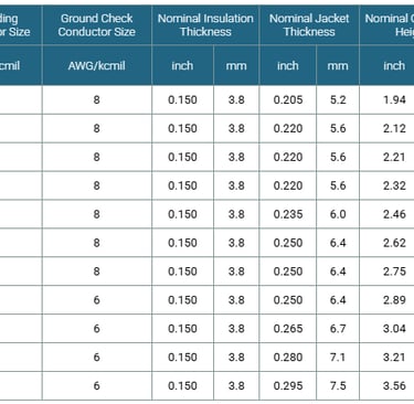
The SHD-GC cable specifications reflect a comprehensive understanding of industrial power requirements. This three-conductor round cable 8kV system utilizes precision-engineered tinned copper conductors arranged in a symmetrical configuration, providing balanced electrical characteristics and enhanced corrosion resistance in humid mining environments.
The voltage rating of 8kV (phase-to-phase) positions this cable for medium-voltage distribution applications where standard low-voltage solutions prove inadequate. Thermal capabilities include a continuous operating temperature of 90°C, with short-circuit temperature ratings reaching 250°C for emergency conditions. This thermal performance ensures reliable operation even when cables are coiled or bundled during temporary installations.
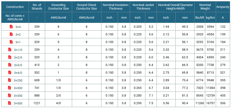
Cable dimensions vary according to conductor size, with overall diameters optimized for both current-carrying capacity and mechanical flexibility. The minimum bending radius specification of 8 times the overall diameter (8×OD) ensures the cable can navigate complex routing paths around mining equipment without compromising the internal conductor or insulation structures. Weight specifications range from moderate to heavy depending on conductor gauge, requiring appropriate handling equipment for larger conductor sizes during installation and maintenance operations.
Physical flexibility remains a paramount design consideration, as mining equipment frequently relocates throughout operational shifts. The cable construction permits repeated flexing cycles without degradation of electrical properties or mechanical integrity, a critical factor distinguishing portable power cable for mining equipment from stationary installation cables.
The conductor material consists of stranded annealed tinned copper, available in various sizes to accommodate different current requirements. Conductor sizing follows American Wire Gauge (AWG) or metric standards, with common sizes ranging from smaller gauges for auxiliary equipment to large conductors exceeding 500 kcmil for primary power distribution to high-horsepower machinery.
Insulation thickness varies proportionally with conductor size and voltage rating, ensuring adequate dielectric strength across all cable variants. The EPR insulation layer typically ranges from several millimeters for smaller conductors to substantial thickness on larger sizes, providing voltage withstand capability well exceeding the nominal 8kV rating to account for transient overvoltages and aging factors.
Construction Details & Materials
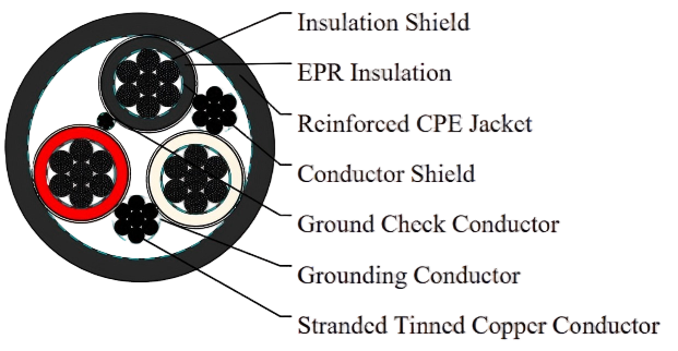
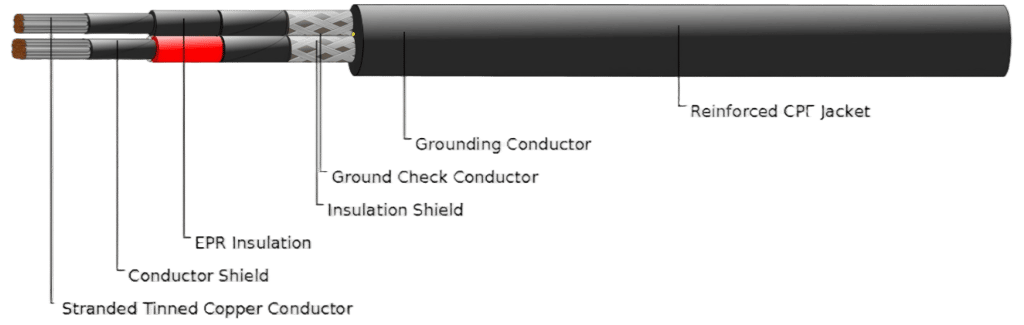
The internal architecture of this cable system exemplifies modern power transmission engineering. At the core, stranded annealed tinned copper conductors provide the primary current-carrying pathway. Stranding improves flexibility compared to solid conductors while maintaining excellent electrical conductivity. The tinning process—applying a thin tin coating to copper strands—significantly enhances corrosion resistance, particularly valuable in damp underground mining environments where untreated copper would rapidly oxidize.
Surrounding each conductor, an EPR insulation cable layer provides primary voltage isolation. Ethylene Propylene Rubber (EPR) insulation offers superior electrical properties across a wide temperature range, excellent resistance to thermal aging, and robust performance in the presence of moisture. Unlike older insulation materials, EPR maintains its dielectric strength even after prolonged exposure to heat and mechanical stress, extending overall cable service life.
Between the conductor and insulation, and again over the insulation layer, conducting and insulation shield systems manage electrical field distribution. The conductor shield ensures uniform voltage stress distribution across the insulation surface, preventing localized electrical concentrations that could initiate insulation breakdown. The insulation shield, typically a semiconducting tape or extruded layer, contains the electrical field within the cable structure and provides a consistent ground reference.
The CPE jacket power cable technology represents the final protective barrier. Chlorinated Polyethylene (CPE) exhibits exceptional resistance to abrasion, tearing, and environmental degradation—far superior to standard PVC compounds. This shielded conductor cable design incorporates the jacket as a critical mechanical protection element, capable of withstanding impact from rock fragments, scraping against rough surfaces, and the general abuse inherent to mobile mining operations.
Within the cable assembly, dedicated ground check and grounding conductor systems provide fault protection and equipment grounding. The ground check conductor enables continuous monitoring of grounding system integrity, a safety feature mandated in many mining jurisdictions. The primary grounding conductor, typically smaller than the phase conductors but substantial in cross-section, ensures rapid fault clearing and personnel protection in ground-fault conditions.
For enhanced mechanical protection, reinforced power cable construction may incorporate additional elements such as aramid fiber reinforcement or textile braiding beneath the outer jacket. These heavy-duty cable jacket materials create a composite structure that resists cutting, tearing, and abrasion far better than single-layer constructions.
The assembly process positions the three insulated and shielded conductors along with grounding conductors within a common jacket. Fillers—typically extruded polymer compounds—occupy interstitial spaces between conductors, maintaining geometric stability and providing additional mechanical cushioning. Binding tape may be applied over the conductor assembly before jacket extrusion, preventing conductor displacement during manufacturing and service.
Industrial cable insulation options beyond standard EPR include crosslinked polyethylene (XLPE) for certain applications, though EPR remains preferred for portable cables due to superior flexibility retention. The insulation system must balance dielectric strength, thermal performance, mechanical properties, and flexibility—a complex optimization where EPR excels for mobile mining applications.
Standards & Compliance
Compliance with recognized industry standards provides assurance of safety, performance, and interoperability. The ICEA S-75-381 standard, published by the Insulated Cable Engineers Association, establishes comprehensive requirements for thermoplastic and crosslinked polyethylene insulated shielded power cables. This standard addresses conductor design, insulation thickness, shielding requirements, jacket specifications, and performance testing protocols.
NEMA WC 58 cable certification indicates compliance with National Electrical Manufacturers Association standards for portable and power feeder cables used in mines. NEMA WC 58 specifically addresses the unique challenges of mining environments, including requirements for flame resistance, mechanical durability, and electrical performance under demanding conditions.
For operations in Canada and international markets recognizing Canadian standards, CAN/CSA C22.2 No. 96 certification demonstrates compliance with Canadian Standards Association requirements for portable power cables. This standard encompasses similar performance criteria to US standards while addressing specific Canadian regulatory requirements.
Material specifications often reference ASTM cable standards for constituent components. ASTM (American Society for Testing and Materials) standards govern copper conductor purity, insulation material properties, jacket compound formulations, and numerous other material characteristics. For instance, ASTM B33 specifies requirements for tinned soft or annealed copper wire, while ASTM D2655 addresses requirements for crosslinked polyethylene insulation materials.
Certification overview documents typically accompany cable shipments, providing traceability to specific production lots and confirming that testing protocols have been completed successfully. Industry standards adherence for safety and performance extends beyond initial manufacturing to include periodic testing and quality assurance programs throughout the cable's service life.
International and regional certification support varies by application and jurisdiction. Mining operations in different countries may require additional certifications or testing to local standards, necessitating close collaboration between cable manufacturers, equipment suppliers, and regulatory authorities.
Testing protocols mandated by these standards include AC voltage withstand testing to verify insulation integrity, DC resistance measurements confirming conductor sizing accuracy, insulation resistance testing evaluating leakage current characteristics, and flame testing demonstrating fire resistance performance. Physical testing addresses tensile strength, elongation, tear resistance, and low-temperature flexibility of jacket materials.
Quality assurance extends to manufacturing process controls, with standards specifying requirements for production testing frequency, documentation retention, and traceability systems ensuring every cable can be traced to specific production records, material lot numbers, and test results.
Applications in Mining & Heavy Industry
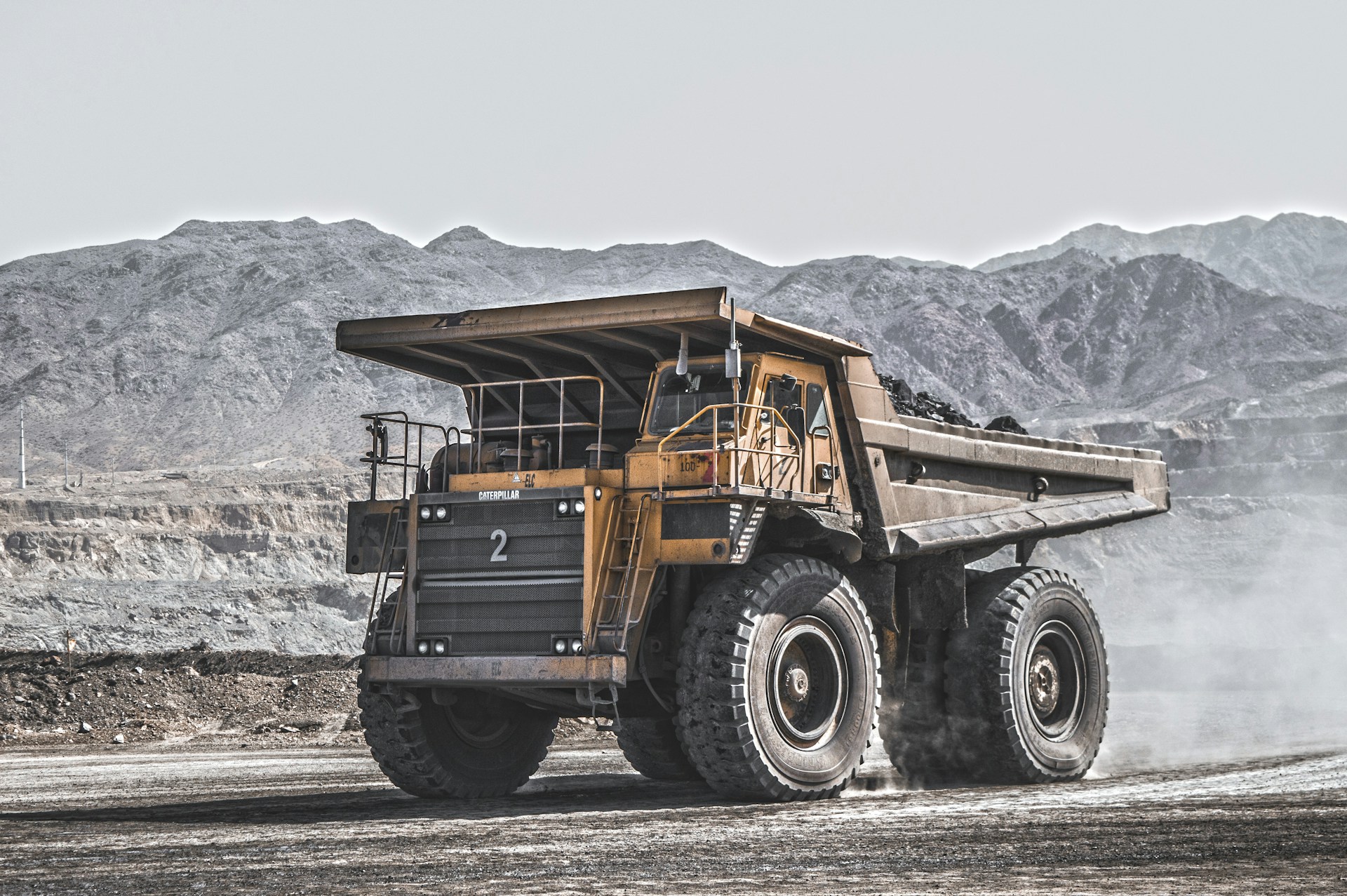
The versatility of this cable system supports diverse applications across mining and heavy industrial sectors. Longwall shearer cable applications represent one of the most demanding use cases. Longwall mining—a highly productive underground coal extraction method—employs massive shearer machines that traverse back and forth along coal faces hundreds of meters long. The continuous miner power cable must endure constant flexing, severe abrasion from coal dust, and potential impact from roof falls or equipment collisions, all while maintaining electrical integrity to power cutting drums drawing hundreds of kilowatts.
Continuous miners, used for room-and-pillar mining operations, present similar challenges but with different movement patterns. These machines advance into solid coal seams, requiring cable management systems that accommodate both longitudinal advancement and frequent repositioning. The mobile mining equipment cables must maintain flexibility even when contaminated with coal dust and water, operating reliably despite being dragged across rough mine floors.
Electric shovels used in surface mining operations demand cables capable of handling high current loads—often exceeding 1000 amperes—while enduring constant repositioning as the shovel rotates and moves between loading positions. Dredge and shovel power solutions must account for the additional challenge of water exposure, as dredging operations occur in aquatic environments where cable submersion may be unavoidable.
Drilling operations, whether for exploration, blasting, or ground support installation, utilize mobile drilling equipment requiring frequent cable disconnection and reconnection. The cable terminations must withstand repeated mating cycles while maintaining electrical contact integrity and environmental sealing.
Underground and surface mining environments present distinct challenges. Underground operations contend with limited space, poor ventilation, high humidity, and the constant presence of coal dust or mineral particulates. Surface operations expose cables to ultraviolet radiation, extreme temperature variations, and often more severe mechanical abuse from heavy mobile equipment traffic.
Use cases extend beyond mining to include tunneling operations, large-scale construction projects, shipyard applications, and any industrial setting requiring mobile power distribution in demanding conditions. High-impact environments benefit from the cable's reinforced construction, while operations involving abrasive conditions rely on the superior jacket durability. Temperature fluctuations, whether from seasonal variations or proximity to heat sources, remain well within the cable's thermal operating envelope.
Quarrying operations utilize similar equipment to surface mining, with comparable cable requirements for rock drills, crushers, and conveyor systems. Demolition contractors employ high-powered electric breakers and cutting equipment requiring robust portable power cables. Large marine vessels and offshore platforms use heavy-duty portable cables for temporary power distribution during construction, maintenance, and emergency situations.
The longwall shearer application deserves additional attention due to its particularly severe operating conditions. Shearers operate continuously, often 24 hours per day, with cables flexing thousands of times per shift as the machine traverses the coal face. Cable management systems must accommodate cable lengths exceeding 300 meters while preventing excessive wear from contact with mine floor irregularities and roof support structures.
Performance & Durability Features
The designation "extra-heavy-duty" reflects genuine performance characteristics rather than marketing hyperbole. The flame-resistant power cable design incorporates materials and construction techniques specifically selected for their fire safety properties. CPE jacket compounds include flame-retardant additives that limit flame propagation, reduce smoke generation, and minimize toxic gas emission during combustion—critical safety features in confined mining spaces where evacuation may be challenging.
The abrasion-resistant cable outer jacket withstands mechanical wear from dragging across rock surfaces, contact with steel equipment frames, and the grinding action of mineral dust. Standard PVC jackets would quickly abrade through under such conditions, exposing inner cable layers to damage. CPE's superior abrasion resistance, often quantified through standardized scrape and gouge testing, extends cable service life by factors of three to five compared to conventional constructions.
Mining-grade power cable specifications address resistance to oils, chemicals, and environmental degradation. Underground mining equipment uses hydraulic oils, lubricants, and sometimes chemical additives in dust suppression systems. The CPE jacket maintains its physical properties despite prolonged contact with these substances, preventing the swelling, softening, or embrittlement that would compromise mechanical protection.
Thermal performance at elevated operating temperatures extends beyond the 90°C continuous rating. During high-load conditions or when cable cooling is restricted by coiling or bundling, internal temperatures may approach design limits. EPR insulation maintains excellent dielectric properties at these temperatures, avoiding the thermal degradation characteristic of lesser insulation materials. The thermal aging resistance of EPR ensures that even after years of operation at elevated temperatures, the insulation retains adequate electrical strength and mechanical integrity.
Flexibility and handling characteristics directly impact operational efficiency. Despite its robust construction, the cable maintains sufficient flexibility for manual handling and routing through equipment cable management systems. The relationship between conductor size, insulation thickness, and jacket design has been optimized to achieve maximum flexibility consistent with required mechanical protection. Durable portable power cables for tough environments must balance these competing requirements—excessive flexibility might compromise mechanical strength, while extreme rigidity would render the cable impractical for mobile applications.
The flame-resistant mining equipment cables undergo rigorous testing to verify fire safety performance. Vertical flame tests assess flame propagation characteristics, while smoke density testing quantifies particulate generation during combustion. Toxicity testing evaluates the chemical composition of combustion gases, particularly important for underground applications where mine ventilation systems must manage any fire-related atmospheric contamination.
Cold temperature performance ensures cable flexibility in surface mining operations during winter months or in arctic climates. The CPE jacket formulation maintains adequate flexibility at temperatures well below freezing, preventing the brittleness that afflicts standard PVC jackets in cold conditions. This cold-temperature capability proves essential for equipment operating outdoors in northern mining regions.
Water resistance protects against moisture ingress that could degrade electrical insulation or corrode conductors. While not designed for continuous submersion, the cable withstands temporary water exposure from rain, equipment washing, or contact with wet surfaces common in mining environments. Proper termination sealing provides additional moisture protection at connection points.
Customization & Options
While standard configurations address most applications, specialized requirements often necessitate customization. Custom cable jackets can be formulated for specific environmental challenges. Operations in extremely cold climates may require jacket compounds that remain flexible at temperatures well below standard ratings, while applications involving specific chemical exposures might specify jacket formulations with enhanced resistance to particular substances.
Cable material options extend beyond CPE to include alternative jacket compounds. Chlorosulfonated Polyethylene (CSP) offers enhanced weather resistance and improved high-temperature performance, making it preferred for surface mining applications with significant solar exposure. Polychloroprene (PCP, also known as Neoprene) provides excellent oil resistance and maintains flexibility across wide temperature ranges, though at higher cost than CPE. Nitrile Butadiene Rubber (NBR) excels in applications involving petroleum products, while PVC jacket alternatives may be specified for budget-conscious applications with less demanding mechanical requirements.
The reinforced fiber jacket construction represents a significant mechanical upgrade. A two-layer jacket configuration incorporates a reinforcing fiber layer—typically aramid or polyester textile—between an inner CPE layer and an outer CPE covering. This composite construction provides exceptional tear resistance and cut-through protection, valuable in applications where cables might be crushed between heavy objects or where sharp rock edges pose cutting hazards.
Custom specifications for specialized applications might address conductor configuration (phase conductor sizing variations), insulation thickness (for higher voltage ratings), or overall cable diameter constraints (for routing through restricted spaces). Shield designs can be customized for specific electrical performance requirements, while grounding conductor sizing may be adjusted for particular fault current conditions.
Tailored power cable solutions for industrial needs often emerge from collaboration between cable engineers and end users. A mining operation experiencing premature cable failures due to specific site conditions might work with manufacturers to develop a cable variant addressing those particular challenges, whether through jacket compound modifications, reinforcement additions, or construction geometry adjustments.
The availability of alternative jacket materials for portable cables ensures that optimal solutions exist for diverse operating environments, chemical exposures, and mechanical stress conditions. Selection among these options requires careful analysis of application requirements, environmental conditions, and cost-benefit considerations.
Color coding options allow customization for voltage identification, phase designation, or equipment assignment. While black remains the standard jacket color for mining cables, specific operations may request colored jackets or longitudinal stripes for organizational purposes. Such customization facilitates cable management in complex installations with multiple voltage levels or equipment assignments.
Conductor material alternatives occasionally arise, such as aluminum conductors for weight reduction in very long cable runs where copper weight becomes prohibitive. However, copper remains strongly preferred for portable mining cables due to superior flexibility, fatigue resistance, and termination reliability compared to aluminum.
Special length requirements can be accommodated, with cables manufactured in continuous lengths eliminating splice points that represent potential failure locations. Conversely, cables can be supplied in standardized lengths matching specific equipment cable management system capacities, simplifying inventory management and replacement procedures.
Installation & Handling Guidelines
Proper installation procedures significantly influence cable performance and longevity. Portable power cable installation begins with pre-installation inspection: verify cable integrity, confirm specification match to application requirements, and check that termination components are compatible and available. Uncoil cable carefully, avoiding kinks or sharp bends that might damage internal construction. For large conductor sizes, mechanical assistance may be required to manage cable weight safely.
Cable management best practices for mobile mining equipment include providing adequate strain relief at termination points, ensuring cable support systems prevent excessive bending at equipment connection points, and implementing cable retrieval systems that prevent dragging cable across sharp obstacles. Where cables cross traffic paths, protective measures such as temporary bridges or buried routing protect both cables and vehicle tires from damage.
Storage and maintenance recommendations emphasize protecting cables from environmental extremes when not in use. Store cables indoors or under protective covering to minimize UV exposure and temperature cycling. Coil cables loosely, respecting minimum bending radius limitations even during storage. Inspect cables regularly for jacket damage, paying particular attention to high-stress areas near terminations and points where cables contact equipment or ground surfaces.
Industrial cable safety protocols address the hazards inherent to medium-voltage power systems. De-energize cables before handling or termination work, and verify de-energization using appropriate testing equipment. The 8kV rating, while considered medium voltage, presents serious electrocution hazards requiring qualified personnel and proper safety procedures. Ground-fault protection systems must be functional before energizing cables, and personnel should be trained to recognize ground-fault indicators.
Mining equipment cable routing requires attention to operational patterns. Analyze equipment movement patterns to identify optimal cable routing that minimizes flexing cycles and mechanical stress. Avoid routing cables where they might be pinched between moving equipment components or crushed by mobile equipment traffic. Consider installing cable management accessories such as festoon systems, cable reels, or guided trolley systems for applications involving repetitive movement patterns.
Handling precautions for heavy-duty cables include using appropriate lifting equipment for large conductor sizes, avoiding dragging cables over sharp edges, and protecting cable ends from contamination during storage and installation. Termination procedures must follow manufacturer specifications precisely, as improper terminations represent the most common failure point in cable systems.
Cable pulling techniques for initial installation differ from those used for stationary cables. Portable cables should never be pulled by wrapping around drum flanges or through sharp-edged cable guides. Use proper cable grips or basket-weave pulling configurations that distribute tension across the cable circumference without concentrating stress on individual conductors.
Termination best practices require appropriate tools, clean working conditions, and attention to detail. Strip jacket and insulation layers using tools designed for the purpose rather than improvised cutting methods that might nick conductors or leave rough edges. Apply semiconducting shielding termination tape smoothly without wrinkles or gaps that could create voltage stress concentrations. Torque connection hardware to specified values using calibrated tools, as both under-tightening and over-tightening create reliability problems.
Environmental protection at terminations includes heat-shrink boots, tape wrapping, or molded rubber components depending on voltage level and environmental severity. Moisture intrusion at poorly sealed terminations causes gradual insulation degradation and eventual tracking failures, making proper environmental sealing essential for long-term reliability.
Advantages Over Standard Cables
The heavy-duty power cable benefits become apparent when comparing lifecycle costs and operational reliability. While initial purchase costs exceed standard cables, the superior durability in high-stress environments translates to extended replacement intervals and reduced downtime costs. A standard cable might require replacement every 12-18 months in severe mining applications, while properly specified heavy-duty cables often achieve 3-5 year service lives or longer.
Compliance with international safety standards provides assurance that cables meet rigorous performance requirements verified through standardized testing. This compliance facilitates equipment approval processes in jurisdictions with strict mining safety regulations and reduces liability concerns associated with substandard electrical equipment.
Industrial-grade cable advantages include predictable performance characteristics based on well-documented material properties and construction specifications. Engineering calculations for voltage drop, current capacity, and fault current withstand become reliable when based on certified cable specifications, whereas non-standard cables may exhibit unpredictable variations in electrical properties.
Mining equipment cable reliability directly impacts production continuity. Unexpected cable failures halt operations, idling expensive equipment and personnel while replacement cables are retrieved and installed. In underground operations, accessing failed cables may require complex logistics and create safety hazards. The enhanced reliability of properly specified heavy-duty cables minimizes these operational disruptions.
Cost-effectiveness for demanding operations must be evaluated over complete lifecycle periods rather than initial purchase price alone. Total cost of ownership includes purchase price, installation labor, expected service life, replacement costs, and operational downtime. When analyzed from this perspective, premium cables often prove more economical than budget alternatives.
Longer service life and reduced replacement frequency yield additional benefits beyond direct cost savings. Reduced replacement frequency minimizes exposure of maintenance personnel to hazards during cable change-out operations, decreases waste generation from disposed cables, and reduces inventory management complexity.
Safety advantages extend beyond regulatory compliance to include real-world accident prevention. Superior flame resistance limits fire propagation during electrical faults, providing additional evacuation time for personnel. Enhanced mechanical durability reduces the likelihood of jacket damage that might expose energized conductors, preventing contact injuries. Reliable grounding systems ensure predictable fault-clearing behavior, protecting personnel from ground-fault hazards.
Operational flexibility increases when cables can be deployed across multiple equipment types and applications rather than requiring specialized cables for each use case. The robust specifications of heavy-duty mining cables often exceed requirements for less demanding applications, allowing consolidated inventory and simplified procurement.
Performance consistency throughout the cable's service life maintains predictable electrical characteristics rather than the gradual degradation characteristic of marginal cable designs. Voltage drop remains stable, insulation resistance stays within acceptable ranges, and mechanical properties don't deteriorate prematurely, ensuring consistent equipment performance over years of operation.
Environmental & Safety Features
Fire resistance and flame-retardant properties address critical safety concerns in confined mining spaces. Flame-resistant industrial cable construction limits fire propagation should ignition occur, whether from electrical faults, external fire sources, or explosive atmospheres. The CPE jacket compound includes halogenated flame retardants that interfere with combustion chemistry, raising ignition temperature and reducing flame spread rates.
Beyond basic flame resistance, modern safe mining equipment power cables address smoke and toxicity concerns. During combustion, cable materials decompose, releasing gases and particulates. Standard PVC cables produce dense black smoke containing hydrochloric acid, severely reducing visibility and creating respiratory hazards. CPE compounds generate significantly less smoke and toxic gas, improving survivability during underground fire emergencies and facilitating evacuation.
Environmentally compliant cable solutions consider lifecycle environmental impacts. While the CPE jacket material contains chlorine—raising environmental concerns about disposal—the extended service life reduces overall material consumption compared to frequently replaced standard cables. Some manufacturers offer take-back programs for end-of-life cables, facilitating responsible recycling of copper conductors and appropriate disposal of insulation and jacket materials.
Worker safety considerations extend beyond electrical and fire hazards to include ergonomic factors. Cable weight and flexibility affect manual handling injury risk, particularly when installation crews must manipulate large conductor sizes in confined spaces. The balance between mechanical protection (requiring heavier construction) and handling practicality represents an ongoing design challenge, with optimal solutions varying by application.
Ground-fault protection capabilities depend critically on proper grounding conductor design and connection integrity. The dedicated grounding conductor provides a low-impedance path for fault currents, ensuring ground-fault protective relays operate within designed time parameters. Ground check conductor systems provide continuous verification that grounding connections remain intact, alerting operators immediately if grounding integrity is compromised.
Low-smoke-zero-halogen (LSZH) cable variants represent an environmental and safety advancement for applications where fire safety concerns override other considerations. These cables substitute halogen-free polymer compounds for CPE, eliminating acid gas generation during combustion. However, LSZH compounds typically sacrifice some mechanical durability compared to CPE, requiring careful application assessment.
Electromagnetic compatibility features include proper shield grounding practices that minimize electromagnetic interference (EMI) radiation from power cables. While 60 Hz power frequency poses minimal EMI concerns, harmonic currents from variable frequency drives can generate significant electromagnetic fields if not properly managed through shield grounding.
Electrical safety features incorporated into cable design include voltage rating margins providing cushion above nominal system voltage, insulation thickness exceeding minimum requirements for enhanced safety factor, and shield systems that contain electrical fields within cable structure rather than allowing field extension into surrounding environment.
Common Cable Challenges and Solutions
What causes premature jacket wear in mining applications?
Premature jacket wear typically results from one or more of three primary mechanisms: abrasion from repeated contact with rough surfaces, chemical attack from exposure to incompatible substances, or mechanical damage from excessive bending or crushing forces.
The abrasion mechanism occurs when cables drag across rock surfaces, concrete floors, or metal equipment frames. Each contact episode removes microscopic amounts of jacket material; over thousands of cycles, this cumulative wear penetrates the jacket exposing inner cable layers. High-traffic areas where cables repeatedly traverse the same path experience accelerated abrasion compared to cables that remain relatively stationary.
Chemical attack manifests when jacket materials contact substances that degrade the polymer matrix. Petroleum products, hydraulic fluids, and some cleaning solvents can penetrate CPE jackets causing swelling, softening, or chemical bond breakdown. Prolonged exposure to incompatible chemicals progressively weakens jacket material until mechanical integrity fails.
Mechanical damage from excessive bending concentrates stress at bend locations, creating flex fatigue that eventually cracks the jacket. Sharp bends exceeding minimum radius specifications immediately damage jacket material, while repeated flexing at slightly excessive bend radii causes progressive fatigue failure. Crushing forces from heavy equipment running over cables or pinching between moving components creates permanent deformation and potentially tears jacket material.
Solution: Implement protective measures at high-wear locations such as cable guides with smooth bearing surfaces, chemical-resistant conduit for areas with chemical exposure, and cable management systems that maintain bending radius limits. For particularly severe applications, specify reinforced fiber jacket construction or upgrade to more abrasion-resistant jacket compounds like CSP.
Physical protection devices include cable trays with rolled edges, flexible conduit through high-traffic zones, and sacrificial wear sleeves at equipment attachment points. Chemical resistance improvements come from selecting jacket compounds specifically formulated for anticipated exposure—NBR for petroleum environments, special CPE formulations for hydraulic fluid contact.
Bending radius control requires disciplined cable management: install radius guides at direction changes, use cable reels with appropriate drum diameters, and train personnel to avoid creating sharp bends during cable handling. Regular inspection programs identify emerging jacket damage before complete failure, allowing preventive repair or replacement.
Why do cables fail at termination points?
Termination point failures occur due to several factors: inadequate strain relief allowing mechanical stress to concentrate at electrical connections, moisture ingress through improperly sealed terminations degrading electrical connections, and thermal cycling causing connection loosening over time.
Strain relief deficiency allows cable weight and movement forces to transmit directly to electrical connections. These connections—crimped lugs, compression fittings, or bolted terminals—cannot withstand repeated mechanical loading without eventual loosening or fracture. Each equipment movement or cable repositioning event stresses the connection, progressively degrading electrical contact quality and mechanical integrity.
Moisture ingress occurs when termination sealing proves inadequate for environmental conditions. Water entering the termination area contacts exposed conductors and connection hardware, creating corrosion that increases electrical resistance and reduces current capacity. In shielded cables, moisture reaching the shield termination creates tracking paths along insulation surfaces, eventually causing complete insulation failure.
Thermal cycling from load current variations causes expansion and contraction of connection components. Bolted connections subjected to thermal cycling gradually loosen as metal components creep under thermal stress. This loosening increases contact resistance, generating additional heat that accelerates the degradation cycle.
Solution: Use termination kits specifically designed for the cable type and voltage rating, ensuring proper strain relief installation. Apply dielectric sealant at shield terminations to exclude moisture. Implement periodic inspection and re-torquing programs for bolted connections. Consider upgrading to molded termination systems for critical applications requiring maximum reliability.
Strain relief design should support cable weight independently of electrical connections, using mechanical clamps or grips that distribute forces across cable jacket rather than concentrating load at termination points. Cable strain relief hardware should be rated for cable weight plus dynamic loading from equipment movement.
Moisture sealing requires multiple barrier layers: heat-shrink boots with adhesive inner layers, self-amalgamating rubber tape wrapped with half-overlap, and mechanical outer protection. For outdoor or wet locations, add cable glands with compression sealing and drip loops preventing water migration into connection areas.
Connection maintenance programs should include infrared thermography inspection identifying hot connections requiring attention, resistance measurement detecting degrading contact quality before catastrophic failure, and scheduled torque verification using calibrated tools. Documentation of torque values and inspection results enables trending analysis predicting when connections will require service.
How can ground-fault sensitivity be improved?
Ground-fault protection systems may fail to detect high-resistance ground faults or respond too slowly to provide adequate personnel protection, particularly as cable and equipment insulation ages and develops leakage currents.
Detection sensitivity limitations arise from protective relay design, system capacitive charging current, and background leakage current that masks incipient faults. Standard ground-fault relays typically require minimum fault current levels—often 5-25 amperes—to guarantee operation. High-resistance ground faults may not generate sufficient current to reach this threshold, particularly in systems with elevated insulation resistance where fault impedance remains high.
System capacitive charging current flows continuously in shielded cable systems, appearing identical to ground-fault current from the relay's perspective. Long cable runs accumulate substantial capacitance requiring significant charging current when energized. This charging current raises the minimum detectable fault current threshold, potentially masking low-level ground faults.
Background leakage current from aged insulation, moisture contamination, or equipment design characteristics creates continuous current flow through grounding systems. This normal leakage current may approach or exceed ground-fault relay pickup settings, forcing higher relay settings that compromise sensitivity or creating nuisance trips if settings remain low.
Solution: Verify ground-fault relay sensitivity settings appropriate for cable length and system capacitance. Implement insulation resistance testing programs to identify deteriorating cable insulation before complete failure occurs. Consider zero-sequence current transformers for enhanced ground-fault detection in multi-cable installations. Ensure grounding conductor sizing provides adequate fault current capacity for rapid relay operation.
Relay setting optimization balances sensitivity against nuisance trip avoidance. Calculate system capacitive charging current based on cable length, capacitance per unit length, and operating voltage. Set relay pickup current above charging current but below dangerous fault current levels. For systems with high charging current, consider directional ground-fault relays that distinguish fault current from capacitive current.
Insulation testing programs using megohm meters or insulation resistance analyzers identify cables with degrading insulation before ground faults develop. Trending insulation resistance measurements over time reveals deterioration patterns, enabling proactive cable replacement before failure. Polarization index testing provides additional insight into insulation condition, with low polarization indices indicating moisture contamination or aging.
Zero-sequence current detection provides enhanced sensitivity compared to residual current measurement. By installing current transformers that encircle all phase conductors simultaneously, only unbalanced current (ground-fault current) produces transformer output. This approach eliminates capacitive charging current interference and enables sensitive fault detection even in long cable systems.
Grounding conductor sizing verification ensures adequate capacity for maximum anticipated ground-fault current. Undersized grounding conductors exhibit high impedance limiting fault current magnitude and slowing protective device operation. Calculate maximum ground-fault current considering source capacity, cable impedance, and grounding system resistance, then verify grounding conductor size provides adequate capacity with appropriate safety margin.
What causes cable overheating during normal operations?
Cable overheating below rated current capacity suggests problems such as poor electrical connections creating high-resistance heat sources, inadequate cable cooling from tightly coiled or bundled configurations, or harmonic current content exceeding cable thermal design assumptions.
Poor electrical connections develop from inadequate initial installation, mechanical vibration causing loosening over time, or corrosion increasing contact resistance. High-resistance connections generate heat proportional to current squared times resistance (I²R losses). Even moderate resistance increases create substantial heating at high current levels, potentially reaching temperatures that damage insulation or create fire hazards.
Inadequate cooling occurs when cable installation prevents normal heat dissipation. Cables generate internal heat from conductor resistance; this heat must transfer through insulation and jacket layers to surrounding environment. Tightly coiled cables trap heat within coil interior, while bundled cable groups prevent air circulation needed for convective cooling. Both scenarios cause cable temperature to exceed ratings despite operating within nominal current limits.
Harmonic current content from non-linear loads such as variable frequency drives adds heating effects not accounted for in standard ampacity ratings. Harmonic currents increase effective RMS current beyond fundamental frequency current, and skin effect concentrates high-frequency harmonic currents near conductor surface, effectively reducing conductor cross-sectional area. Combined effects can increase cable heating 20-50% compared to purely sinusoidal current.
Solution: Perform infrared thermography inspections to identify hot connections requiring cleaning and re-torquing. Review cable installation for cooling restriction—cables should be spread out when possible rather than bundled tightly. For installations with significant harmonic content (variable frequency drives, etc.), de-rate cable ampacity or specify larger conductor sizes to accommodate additional heating.
Thermography inspection programs should operate under loaded conditions capturing cables at normal operating current. Temperature differentials between connection points and adjacent cable sections indicate problem connections. Temperature rises above ambient exceeding design expectations suggest cooling problems or overloading. Establish temperature baselines for normal operation enabling detection of developing problems through comparison with historical data.
Cable installation review should identify cooling restrictions and implement corrective measures. Uncoil cables completely during operation rather than operating from partial coils. Separate bundled cables where possible, maintaining spacing that permits air circulation. For cables in confined spaces, consider forced air cooling using ventilation fans, or relocate cables to areas with better natural ventilation.
Harmonic current assessment requires measurement of actual current waveforms using true-RMS meters or power quality analyzers. Calculate total harmonic distortion (THD) and individual harmonic magnitudes, then apply appropriate ampacity de-rating factors based on harmonic content. For systems with severe harmonic distortion (THD exceeding 20%), consider installing harmonic filters or using cables specifically designed for non-linear load service.
Why does cable insulation fail prematurely in some installations?
Premature insulation failure may result from overvoltage conditions exceeding insulation design limits, contamination ingress through jacket damage creating conductive paths across insulation surfaces, or thermal aging from chronic overcurrent or poor cooling conditions.
Overvoltage events include transient voltage spikes from switching operations, lightning strikes on surface installations, or ground-fault conditions on ungrounded systems creating phase
How to Reach Us
Get in Touch
SiteMap
Product Catalogue
Festoon Cable
Shore Power Cable




Scan to add us on WeChat