

SHD-GC Three-Conductor Round Portable Power Cable with TPU Jacket 15kV: The Ultimate Solution for Heavy-Duty Mining and Industrial Applications
Discover the SHD-GC three-conductor round portable power cable with TPU jacket 15kV for heavy mobile equipment like draglines and shovels. EPR insulation, tinned copper conductors, ICEA S-75-381 compliant. Shop now!
hongjing.Wang@Feichun
1/19/202621 min read
Introduction
In the demanding world of heavy industrial operations, power distribution equipment must withstand extreme mechanical stress, abrasive conditions, and continuous flexing without compromising electrical safety or performance. The SHD-GC three-conductor round portable power cable with TPU jacket 15kV represents a pinnacle of engineering excellence designed specifically for these challenging environments. This heavy-duty EPR insulated cable delivers exceptional durability and reliability for mobile equipment operating in mining, dredging, and construction applications where standard cables simply cannot survive.
Built to exceed the rigorous requirements of ICEA S-75-381/NEMA WC 58 standards, this portable power cable combines advanced materials science with proven construction techniques. The heavy duty 15kV TPU jacket cable for mining shovels and dredges features ethylene propylene rubber (EPR) insulation rated for continuous operation at +90°C, surrounded by a robust thermoplastic polyurethane (TPU) outer jacket that resists cuts, abrasion, and environmental degradation. Additional compliance with ASTM B 172, ASTM B 33, and CAN/CSA C22.2 No. 96 ensures this cable meets North American standards for conductor quality, construction integrity, and safety performance.
For operations managers, electrical engineers, and procurement specialists tasked with maintaining uptime in critical mining and industrial applications, the SHD-GC cable offers a comprehensive solution that balances flexibility, mechanical strength, and electrical performance in a single, field-proven design.
Applications: Where the SHD-GC Cable Excels
The SHD-GC cable for heavy duty mining equipment and portable power feeders serves as the electrical lifeline for some of the most demanding mobile equipment in industrial operations. Understanding the specific application requirements helps explain why this cable's construction features are essential rather than optional.
Primary Mobile Equipment Applications
Draglines represent perhaps the most demanding application for portable power cables. These massive excavators swing continuously while drawing hundreds of amperes at medium voltage, creating extreme flexing cycles combined with exposure to rock debris, coal dust, and weather extremes. The SHD-GC cable's TPU jacket provides superior abrasion resistance compared to traditional rubber compounds, while the EPR insulation maintains dielectric integrity despite repeated mechanical stress. In surface coal mining operations, draglines operate 24/7 in environments where temperatures swing from -30°C in winter to +40°C in summer, requiring cables that maintain flexibility and electrical performance across this entire range.
Power shovels and excavators require cables that can handle sharp bending around sheaves and drums while resisting damage from rocks, metal fragments, and the harsh chemicals often present in mining environments. During loading operations, these cables may be dragged across blast rock, compressed under equipment tracks, or struck by falling material. The cable's construction with tinned copper conductors and ground check systems ensures both electrical performance and enhanced safety monitoring capabilities essential for these high-value assets. A typical electric mining shovel may consume 3-7 megawatts during peak digging cycles, placing enormous current demands on the portable power cable.
Dredging operations present unique challenges including periodic submersion, exposure to saltwater or chemically aggressive slurries, and continuous mechanical movement. Cutter suction dredges, hopper dredges, and bucket ladder dredges all require power cables that can withstand wet environments while maintaining medium voltage isolation. The TPU jacket's resistance to moisture absorption and chemical attack makes the SHD-GC cable particularly well-suited for these applications, where cable failure can result in costly downtime and environmental concerns. Salt water environments are especially challenging, as chloride ions can accelerate corrosion of unprotected conductors—making the tinned copper construction essential for long service life.
Rotary drills and blast hole drills in surface mining operations demand cables that withstand constant vibration, exposure to drilling fluids, and the sharp edges of drill rig equipment. These machines drill hundreds of holes per week, with the cable flexing continuously as the drill mast raises and lowers. The cable's high flexibility combined with its tough outer jacket allows it to survive in cable trays, festoon systems, and direct ground contact scenarios common in drill yard environments. Drill patterns in large open pit mines may require cables to be repositioned dozens of times per day, emphasizing the importance of handling durability.
Portable Power Feeder Applications
Beyond mobile equipment, this cable excels as a portable power feeder for temporary installations, construction sites, and modular mining operations. When expanding mining operations into new pit areas, temporary substations must be established quickly and relocated as the operation advances. The high flexibility (minimum bending radius of just 8×OD) allows for easier handling during installation and repositioning, while the TPU jacket's resistance to oils, fuels, and industrial chemicals protects the cable during storage and deployment in industrial yards.
The cable's construction also makes it suitable for shore power connections at ports, temporary substation feeders during mine expansion projects, and relocatable equipment power distribution in quarries and aggregate operations where flexibility and durability are equally critical. Construction sites for major infrastructure projects—dams, tunnels, and heavy civil works—benefit from the cable's ability to be installed, moved, and reinstalled without degradation.
In emergency power restoration scenarios, such as restoring service after equipment failures or natural disasters, the SHD-GC cable can be rapidly deployed to re-establish critical power feeds. Its durability ensures it survives the rough handling inevitable during emergency response operations.
Construction Features: Engineering for Extreme Reliability
The exceptional performance of the EPR insulated SHD-GC three-conductor 15kV portable power cable with TPU jacket results from careful selection of materials and precision in manufacturing. Each layer serves specific electrical and mechanical functions that contribute to the cable's overall reliability.
Conductor Design
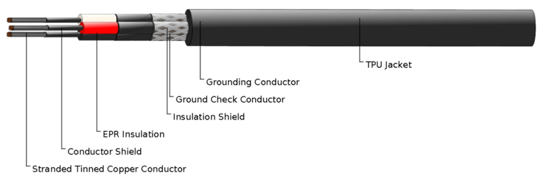
At the cable's core are stranded annealed tinned copper conductors manufactured in full compliance with ASTM B 172 (for stranding configuration) and ASTM B 33 (for tinned copper wire). The annealing process softens the copper, maximizing flexibility while maintaining excellent electrical conductivity. The tinning process—applying a thin layer of tin to copper strands—provides several critical advantages. First, it prevents oxidation that would otherwise increase contact resistance at terminations, which is particularly important in mining environments with high humidity and temperature cycling. Second, tinned conductors resist corrosion in humid or chemically aggressive environments far better than bare copper. Sulfur compounds in coal, salt spray in marine dredging, and industrial chemicals in processing plants all attack bare copper, but are largely resisted by the tin coating. Third, the tin coating facilitates superior crimping and soldering during connector installation, ensuring long-term connection reliability—critical when connector failures can shut down multi-million dollar equipment.
The stranded construction, utilizing Class B or finer stranding depending on conductor size, provides the flexibility essential for portable cable applications while maintaining excellent current-carrying capacity and low electrical resistance. Each conductor may contain hundreds of individual strands, each contributing to the overall flexibility that allows the cable to bend repeatedly without conductor breakage—a failure mode that plagues cables with inadequate stranding in mobile applications. The conductor design accommodates the millions of flex cycles experienced during the cable's operational life.
Conductor and Insulation Shield System
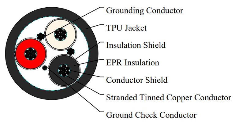
Surrounding each conductor is a semiconducting conductor shield layer that ensures uniform electric field distribution at the interface between the conductor and insulation. This extruded or tape-applied layer eliminates air gaps and surface irregularities that could create localized electrical stress concentrations, which at 15kV operating voltage could lead to partial discharge and eventual insulation failure. At medium voltages, electric field uniformity becomes critical—any protrusion or void can create field intensification that exceeds the breakdown strength of air or insulation materials.
The EPR insulation itself represents the primary dielectric barrier, engineered to withstand the cable's rated voltage while operating continuously at conductor temperatures up to +90°C. Ethylene propylene rubber offers exceptional resistance to thermal aging, ozone attack, and moisture intrusion compared to alternative insulation materials like crosslinked polyethylene (XLPE) or polyvinyl chloride (PVC). EPR's flexible polymer chains maintain elasticity even after years of thermal cycling, whereas more rigid materials can develop cracks that compromise dielectric strength. This translates to longer service life in harsh outdoor environments where temperature cycling and UV exposure are constant concerns—surface mines in desert climates or arctic regions particularly benefit from EPR's thermal stability.
The insulation thickness is precisely controlled to provide the required dielectric strength with appropriate safety margin, typically designed to withstand voltage surges from lightning strikes, switching transients, and equipment faults that can momentarily impose voltages several times the nominal rating.
Over the EPR insulation, an insulation shield consisting of semiconducting tape plus a tinned copper or textile braid provides several functions. The semiconducting layer ensures uniform electric field distribution at the outer insulation boundary, preventing surface tracking and voltage stress concentrations. The metallic or textile braid offers mechanical protection during installation and handling while serving as a low-impedance ground fault return path. This shield construction is critical for proper operation of ground fault protection systems that safeguard personnel and equipment—when insulation fails, fault current flows through the shield to trip protective relays before dangerous voltages can develop on equipment frames.
Ground Check and Grounding Conductors
A distinguishing feature of mining and heavy equipment cables is the inclusion of dedicated safety conductors. The ground check conductor, consisting of tinned copper with yellow polypropylene insulation, allows continuous monitoring of the cable's grounding system integrity. Specialized ground fault relays monitor this conductor to detect insulation degradation or ground faults before they become dangerous, enabling predictive maintenance and preventing catastrophic failures. The ground check system creates a monitoring loop that indicates if the equipment grounding conductor has been damaged or disconnected—a condition that could leave equipment frames energized without anyone knowing until a worker makes contact.
This monitoring capability is mandated by mining safety regulations in many jurisdictions, reflecting the critical importance of maintaining grounding integrity in potentially explosive atmospheres and wet conditions common in mining. The yellow insulation provides instant visual identification during termination and troubleshooting.
The main grounding conductor, also constructed from tinned copper, provides the primary equipment grounding path required by electrical codes. This conductor must carry fault currents safely until protective devices operate, making its adequate sizing and reliable connection essential for personnel safety. Fault currents in 15kV systems can reach tens of thousands of amperes momentarily, creating enormous electromagnetic forces and thermal stress. The grounding conductor's ampacity and mechanical strength must accommodate these extreme transient conditions without failure.
TPU Jacket: Superior Protection
The cable's black thermoplastic polyurethane (TPU) outer jacket represents a significant advancement over traditional chloroprene (Neoprene) or rubber jackets historically used in mining cables. TPU offers exceptional abrasion resistance—often exceeding Neoprene by factors of 3-5 in standardized tests such as the Taber abraser test—which directly translates to longer cable life when dragged across rock surfaces or pulled through cable trays with sharp edges. Field experience in coal mines shows TPU-jacketed cables lasting two to three times longer than comparable Neoprene cables in severe abrasion applications.
TPU also demonstrates superior resistance to cutting and tearing, critical properties when cables are deployed in environments with sharp rocks, metal debris, or excavator bucket teeth. The material's high tensile strength and tear propagation resistance mean that even if the jacket is nicked or punctured, the damage is less likely to propagate into a complete jacket failure. The material maintains flexibility across a wide temperature range, from -40°C to +90°C, without becoming brittle or excessively soft. This temperature range coverage ensures the cable remains handleable and operational whether deployed in Canadian winter surface mines or Australian summer conditions.
Additionally, TPU resists degradation from oils, hydraulic fluids, diesel fuel, and most industrial chemicals commonly encountered in mining and construction environments. Hydraulic oil leaks from equipment, diesel spills during refueling, and exposure to chemical additives in drilling fluids all contact portable cables regularly. TPU's chemical resistance prevents jacket swelling, softening, or cracking that would compromise protection.
The smooth, dense surface of TPU jackets sheds mud, dirt, and moisture more effectively than rougher rubber surfaces, making the cable easier to clean and inspect. This characteristic also reduces the accumulation of conductive contaminants that could create tracking paths and electrical leakage in medium voltage cables—particularly important in coal mining where conductive coal dust can settle on cable surfaces. The black pigmentation provides UV resistance for cables exposed to sunlight, while the smooth finish allows visual inspection to readily identify cuts, abrasion, or other damage that requires attention.
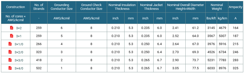
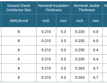
Options and Customization: Tailoring the Cable to Your Operation
While the standard SHD-GC construction meets the needs of most applications, specific operational environments may benefit from alternative configurations. The custom SHD-GC TPU jacket cable options for industrial power feeders allow engineering teams to optimize cable specifications for their unique requirements.
Alternative Jacket Materials
Upon request, the cable can be manufactured with alternative jacket compounds to address specific environmental challenges:
CSP (Chlorosulfonated Polyethylene) jackets offer enhanced chemical resistance and superior flame resistance compared to TPU, making them suitable for applications with extreme chemical exposure or stringent fire safety requirements. CSP resists strong acids and bases better than TPU and provides excellent ozone resistance. However, CSP generally provides lower abrasion resistance than TPU and costs more, making it appropriate for chemically aggressive environments where abrasion is not the primary concern—such as cables near chemical storage areas or acid mine drainage treatment facilities.
PCP (Polychloroprene, commonly called Neoprene) represents the traditional mining cable jacket material, offering good all-around properties including flame resistance, weather resistance, and chemical resistance. Neoprene has decades of proven performance in mining applications and remains an excellent choice for many installations. While PCP costs less than TPU, it typically provides inferior abrasion resistance and flexibility, particularly at temperature extremes below -25°C where Neoprene becomes quite stiff.
NBR (Nitrile Butadiene Rubber) jackets excel in applications with severe oil and fuel exposure, offering maximum resistance to petroleum-based contaminants. Equipment operating in oil sand mining or near fuel storage facilities may benefit from NBR's superior oil resistance. The trade-off is reduced ozone and weather resistance compared to TPU or PCP, making NBR most appropriate for applications where petroleum exposure is severe but outdoor weathering is limited.
PVC (Polyvinyl Chloride) jackets offer the most economical option with adequate performance for less demanding applications, though they provide significantly reduced flexibility at low temperatures (typically unusable below -10°C) and inferior abrasion resistance compared to TPU. PVC may be appropriate for indoor applications or mild climates where cost is paramount and mechanical stress is limited.
Enhanced Two-Layer Jacket Construction
For the most demanding applications—such as dragline duty cycles with extreme abrasion or dredge cables subject to sharp rock contact—a two-layer jacket with reinforcing fiber between layers provides maximum mechanical protection. This construction incorporates a textile reinforcement (typically aramid fiber fabric) between an inner and outer jacket layer, dramatically increasing resistance to cuts and impacts while maintaining reasonable flexibility.
The reinforcing layer acts as a "safety net" that prevents complete jacket penetration from sharp object impacts, giving the cable a second chance to survive damage that would compromise a single-layer jacket. When a sharp object penetrates the outer jacket, the aramid reinforcement arrests the damage, preventing penetration to the underlying insulation shields. This construction is particularly valuable when cable replacement requires expensive equipment downtime or creates safety risks during changeout procedures—such as on offshore dredges or draglines operating in deep pits where cable installation is complex and time-consuming.
The two-layer construction also provides enhanced crush resistance, protecting the cable when heavy equipment drives over it or when buried under rockfall during blasting operations—scenarios that occur with unfortunate regularity in active mining environments.
Mechanical and Thermal Properties: Understanding Operating Parameters
Proper cable installation and handling requires understanding the mechanical and thermal limitations that preserve cable integrity and ensure safety throughout its service life.
Bending Radius Considerations
The minimum bending radius of 8 times the cable's overall diameter (8×OD) represents the tightest curve the cable should experience during installation or operation without risking damage to conductors, insulation, or shields. For example, a cable with a 3-inch overall diameter should not be bent around a radius tighter than 24 inches (8 × 3 = 24 inches).
Exceeding this limit can cause several failure modes: conductor strands may break or kink, creating localized hot spots and reducing current capacity; insulation may crack or separate from shields, creating voids where partial discharge can initiate and propagate; shield braids may bunch or separate, compromising their electrical and mechanical functions; the jacket may develop stress cracks that allow moisture ingress. In mobile equipment applications where cables flex continuously—draglines may flex cables thousands of times per day—respecting bending radius limits directly correlates with cable service life. Cables repeatedly bent beyond minimum radius may fail in months rather than the 5-10 years typical of properly handled cables.
Installation guides, sheaves, and cable reels should be sized appropriately. Cable reels for storage and transport should have a flange diameter of at least 16×OD to maintain the cable in a relaxed state that doesn't approach minimum bending limits. Sheaves on mobile equipment should be inspected regularly to ensure they maintain proper diameter and that grooves haven't worn to sharp edges that create localized stress concentrations.
During installation, particular attention must be paid to bending radius at cable entry points into equipment and around corners in cable trays. Using cable pull socks and proper pulling techniques prevents kinking during installation—once a cable is kinked, the damage is permanent and creates a failure point that will likely eventually fail.
Thermal Management
The +90°C maximum conductor temperature rating defines the cable's continuous current-carrying capacity under specified installation conditions. This rating reflects the EPR insulation's ability to withstand thermal aging while maintaining its dielectric properties throughout the expected cable life (typically 20+ years for properly applied cables). Insulation aging is an exponential function of temperature—operating just 10°C above rated temperature can reduce cable life by half, while maintaining temperature well below maximum can extend life significantly.
Actual current capacity depends on multiple factors including installation method (buried, in tray, in air), ambient temperature, altitude, and grouping with other cables. A cable in direct sunlight on a 40°C day starts with a much higher baseline temperature than the same cable buried underground, dramatically reducing its safe current capacity. Engineering teams should consult ampacity tables in ICEA S-75-381 or perform detailed calculations using methods from IEEE 835 or IEC 60287 to determine safe current ratings for their specific installation.
Thermal overload from sustained overcurrent represents one of the primary cable failure mechanisms in mining applications. The accelerated insulation aging from excessive temperature can reduce cable life from decades to mere years, making proper conductor sizing and thermal monitoring essential for reliable operations. Installing temperature monitoring systems on critical cables—either infrared cameras for periodic inspection or embedded fiber optic temperature sensors for continuous monitoring—allows operations teams to verify cables operate within thermal limits.
Standards and Compliance: Meeting Industry Requirements
The ICEA S-75-381 compliant heavy duty SHD-GC 15kV TPU portable power cable demonstrates conformance with multiple standards that collectively ensure the cable meets electrical safety, performance, and quality requirements for North American industrial applications.
ICEA S-75-381 / NEMA WC 58
This primary standard specifies portable and power feeder cables for mining applications, defining construction details, materials requirements, testing protocols, and performance criteria. Compliance ensures the cable design incorporates appropriate shielding, insulation thickness, jacket properties, and mechanical characteristics for safe medium voltage operation in harsh environments. The standard's testing requirements verify resistance to voltage stress, conductor pulling force, cold bend performance, flame propagation, and other critical properties.
Specific tests mandated by the standard include: dielectric voltage withstand testing to verify insulation integrity at multiples of rated voltage; insulation resistance measurements to confirm bulk resistivity meets specifications; conductor resistance testing to verify proper conductor sizing and material conductivity; cold bend testing at -25°C to ensure flexibility is maintained at low temperatures; flame resistance testing to confirm the cable won't propagate fire; and accelerated aging tests to project long-term performance.
ASTM B 172 and ASTM B 33
These ASTM International standards govern the conductor materials and construction. ASTM B 172 specifies stranding configurations, ensuring conductors have appropriate flexibility and current-carrying capacity for their size and class designation. The standard defines the number of strands, individual strand diameter, and overall geometric configuration for each conductor size class. Class B stranding (specified for most portable cables) provides good flexibility while maintaining reasonable manufacturing cost—finer stranding classes like C or D offer enhanced flexibility for specialized applications but at premium cost.
ASTM B 33 defines requirements for tinned copper wire, including minimum tin coating thickness (typically 1.25 micrometers or greater) and adhesion properties that ensure corrosion protection without compromising electrical conductivity. The standard specifies testing methods to verify tin coating uniformity and adhesion, ensuring the coating won't flake off during cable manufacturing or service. Proper tin coating is essential for long-term connector reliability and corrosion resistance in harsh environments.
CAN/CSA C22.2 No. 96
This Canadian Standards Association specification for portable power cables ensures compatibility with Canadian electrical codes and provides additional performance validation. The standard includes specific requirements for ground conductor sizing, insulation thickness, and jacket properties that may differ slightly from U.S. standards. Cables meeting this standard can be deployed in Canadian mining operations without special approvals or modifications, simplifying procurement for companies operating mines in both countries. The CSA certification mark provides regulatory authorities and safety inspectors immediate confidence that the cable meets Canadian safety requirements.
Common Cable Challenges and Solutions in Mining Applications
Understanding potential problems and their solutions helps operations teams maximize cable life and avoid unexpected failures.
Problem: Premature Jacket Wear from Abrasion
Question: Our dragline cables develop jacket wear at specific locations, exposing the underlying layers within 12-18 months rather than the expected 5-7 years. Visual inspection shows the damage is concentrated in just a few spots rather than distributed along the cable length. What causes this localized damage and how can we prevent it?
Solution: Localized abrasion typically results from the cable repeatedly contacting the same sharp edge or surface—often a cable tray edge with inadequate radius, a sheave flange that has worn sharp, or an equipment frame corner that wasn't properly radiused during manufacturing. Unlike distributed abrasion from dragging cables across rough ground (which causes relatively uniform jacket wear), point-source abrasion concentrates all the wear energy on a small area, rapidly wearing through even the toughest TPU jacket.
Inspect the cable path carefully, both on the equipment and along any fixed cable routing. Look for: cable tray edges with burrs or bent flanges; sheaves with worn grooves that allow cable to contact the flange edge; equipment frame penetrations without proper grommets or wear sleeves; locations where cables cross each other (cables rubbing on cables); and spots where cables contact moving equipment parts during operation.
Solutions include: installing protective wear sleeves (spiral wrap or split loom) at problem contact points; enlarging radiuses with guards or forming wear-resistant inserts at contact points; rerouting the cable to eliminate the abrasive contact entirely; installing additional cable supports to change the catenary and prevent contact; and smoothing sharp edges with grinding and applying protective coatings.
For dragline applications where the cable must flex near sheaves, ensure sheaves are properly sized (typically 20× cable diameter minimum) and that grooves are inspected and replaced when wear creates sharp edges. Rotating the cable 90-180 degrees periodically (if application permits) distributes wear around the circumference rather than concentrating it on one side, potentially doubling jacket life. Schedule this rotation during planned maintenance rather than waiting for failure.
Problem: Ground Fault Indications Without Visible Damage
Question: Our ground fault monitoring system indicates insulation degradation on a shovel cable, but thorough visual inspection shows no obvious cable damage—no cuts, no apparent jacket wear, and no discoloration. The equipment continues operating normally. How do we locate the problem, and is it safe to continue operation while investigating?
Solution: Internal insulation degradation often precedes visible external damage, particularly in cables subjected to repeated flexing, thermal cycling, or moisture intrusion through damaged terminations. Ground fault monitoring systems detect insulation resistance degradation that indicates the cable is approaching failure, providing advance warning before catastrophic breakdown occurs—exactly the safety function they're designed to provide.
First, do NOT ignore the warning. While the equipment may operate normally now, degraded insulation represents a serious safety hazard and impending failure risk. Continuing operation without investigation could result in a ground fault that trips the equipment during a critical production period or, worse, creates a safety incident.
Use insulation resistance testing (megger testing) with a 5kV or higher megohmmeter to confirm deteriorating insulation and quantify the degree of degradation. Compare readings to baseline values (if available) and to manufacturer specifications. Decreasing insulation resistance over time indicates progressive degradation. Then employ time-domain reflectometry (TDR) or other fault location techniques to pinpoint the degraded section. TDR works by sending an electrical pulse down the cable and measuring reflections from impedance changes—damaged insulation creates a characteristic reflection that reveals its location within a few feet.
Common causes of internal degradation without external damage include: moisture intrusion through damaged or improperly installed terminations (water tracking down strands into insulation); localized overheating from poor splices or connections creating hot spots that accelerate insulation aging; mechanical damage to internal components (shield breaks, insulation cracks) from excessive bending that occurred during installation or operation; and chemical contamination that penetrated through jacket defects too small to notice visually.
Once located, the damaged section should be removed and replaced with a properly installed splice, or the entire cable replaced if degradation is extensive. Early detection through regular testing allows planned replacement during scheduled maintenance rather than emergency response to catastrophic failure.
Problem: Connector Failures and Hot Spots
Question: We experience recurring problems with cable connectors overheating and failing, requiring expensive reeliminations every few months. The cable itself appears fine. Infrared inspection shows connector temperatures 40-50°C above ambient during normal operation. What's causing these failures, and how do we achieve reliable connections?
Solution: Connector problems typically stem from inadequate connection quality rather than cable defects. High resistance connections generate heat according to the formula P = I²R, where even small increases in resistance (R) create significant heating when multiplied by the square of current (I). A connection with just 0.001 ohm excess resistance carrying 400 amperes generates 160 watts of heat—enough to cause visible discoloration and progressive failure.
Ensure connectors are properly sized for the actual conductor gauge—using undersized connectors is a common error that guarantees overheating. Verify the connector manufacturer's specifications match the cable conductor size and type. For stranded conductors, all strand layers must make proper contact with the connector barrel. If only outer strands contact the connector, current crowds into those strands, creating localized heating.
Crimping force is critical—too little force leaves gaps between strands and connector barrel (high resistance), while excessive force can damage strands or connector. Use calibrated hydraulic crimping tools and verify crimp dimensions with go/no-go gauges. Die selection must match both connector style and conductor size. Rotating dies or worn tools produce irregular crimps that create hot spots.
Tinned copper conductors require attention to proper surface preparation. While tin coating prevents oxidation in service, contamination or corrosion from improper storage must be removed before assembly. Clean conductor ends with wire brushes (stainless steel, not steel which leaves ferrous particles) and approved solvents. Apply antioxidant compound before assembly if specified by connector manufacturer.
Hot spots at connections indicate high resistance demanding immediate attention. Use infrared thermography to identify developing problems before failure—quarterly thermal scans of all critical connections should be standard practice. Connections more than 30°C above adjacent cable temperature indicate problems requiring investigation. Connections running hot progressively degrade due to thermal cycling, annealing of conductor strands, and oxidation—a developing problem only gets worse until addressed.
When connector failures recur, examine the entire termination process: Are technicians properly trained? Are correct tools being used? Are crimps being inspected and documented? Is storage protecting cables from contamination? Often systematic problems in procedure or tooling explain recurring failures.
Problem: Cable Stiffness in Cold Weather
Question: Our cables become extremely difficult to handle when ambient temperatures drop below -20°C during winter operations. Crews report the cables are stiff as steel bars and won't bend around normal working radiuses. Is this normal behavior, does it indicate a problem with the cable, and are we risking damage by forcing the cables to bend?
Solution: All cable materials stiffen as temperature decreases due to the thermodynamic properties of polymers—molecular chains lose mobility at low temperatures, increasing stiffness. However, TPU maintains significantly better low-temperature flexibility than many alternatives like PVC or standard Neoprene, with most TPU formulations remaining flexible to -40°C.
Extreme stiffness at -20°C suggests either: (a) the cable has exceeded its minimum rated temperature for the specific jacket formulation; (b) the cable has absorbed moisture that freezes at low temperatures, dramatically increasing stiffness; or (c) the cable is an older design with inferior cold-temperature performance.
First, verify the cable's rated temperature range from manufacturer specifications. Some TPU formulations are rated only to -25°C, while arctic-grade formulations perform to -50°C or lower. If operations consistently occur below the cable's rated temperature range, the cable is being used outside its design envelope.
Do NOT force cold-stiffened cables beyond their reduced bending radius capability. At low temperatures, materials become brittle—forcing tight bends can crack jacket and insulation, creating permanent damage that will leak and fail when temperatures rise. The minimum bending radius increases at low temperature (often 12×OD or more at extreme cold vs. 8×OD at room temperature).
Solutions include: Store cables in heated areas before deployment when possible, allowing them to warm to workable temperature before installation. Provide gradual warm-up time—bringing a -30°C cable directly to +20°C can cause condensation problems. Use heating blankets or warm air to heat cables at termination points where bending is necessary. Schedule cable installation and reconnection work during warmer parts of the day. For operations consistently in extreme cold, specify arctic-grade cable with low-temperature jacket formulation during procurement.
If moisture absorption is suspected (indicated by unusual weight or visible water when cutting cable), investigate whether damaged jacket or improper termination sealing is allowing water intrusion. Moisture inside cables freezes at 0°C, dramatically increasing stiffness. Cables should be stored with ends properly sealed and inspected for jacket damage before winter storage.
Problem: Electrical Tracking and Surface Leakage
Question: We've noticed electrical tracking marks on cable jackets near terminations, appearing as branching burn patterns on the surface. Some cables trip ground fault protection intermittently during rain or high humidity. What causes this tracking, and how do we prevent it?
Solution: Electrical tracking occurs when conductive contamination on cable surfaces (coal dust, metal particles, salt, chemical residues) creates leakage current paths, particularly in the high electrical stress zones near terminations and elbows. At medium voltage, even small leakage currents can generate enough heat to carbonize jacket material, creating conductive carbon paths that draw additional current in a progressive failure mechanism.
The smooth TPU jacket surface inherently resists contamination accumulation better than rough rubber surfaces, but can still develop tracking in severe environments. Contributing factors include: inadequate termination stress relief (creating high surface voltage gradients); contamination from coal dust, metal particles, or chemicals; moisture that makes contamination conductive; damaged jacket allowing internal moisture to surface; and improper termination installation leaving sharp conductor ends or inadequate insulation overlap.
Prevention measures: Regular cleaning of cable surfaces, especially near terminations and in high-stress areas. Use appropriate cleaning solutions (mild detergent, avoid petroleum solvents that attack TPU). Inspect and properly size stress relief boots at terminations—these devices distribute electrical stress over a larger area, reducing surface voltage gradient. Ensure termination procedures include proper stress cone or stress relief kit installation per manufacturer instructions. Maintain proper drainage so water doesn't pool around cables. In extreme contamination environments (coal preparation plants, cement operations), consider adding protective sleeving over cables near terminations.
If tracking damage has occurred, the affected cable section must be replaced—tracking creates permanent carbonization that cannot be cleaned away. Once initiated, tracking progressively worsens until failure occurs. Early detection during routine inspections allows planned replacement before catastrophic failure.
Call to Action: Partnering for Power Distribution Excellence
Selecting the right portable power cable represents a critical decision that impacts operational safety, equipment uptime, and long-term maintenance costs in demanding mining and industrial environments. The SHD-GC three-conductor round portable power cable with TPU jacket 15kV delivers proven performance in the world's most challenging applications, backed by comprehensive standards compliance and engineered construction features that address real-world operational demands.
Whether you're specifying cables for a new dragline installation, replacing aging dredge power feeders, upgrading your fleet of mobile mining equipment, or establishing portable power distribution for a major construction project, expert guidance ensures you select the optimal cable configuration for your specific requirements. Parameters to discuss with qualified cable suppliers include: specific equipment type and duty cycle; environmental conditions (temperature extremes, chemical exposure, abrasion severity); installation method and routing constraints; required electrical ratings (voltage, amperage, short circuit capacity); regulatory and standards requirements for your jurisdiction; and delivery schedule and volume requirements.
Contact experienced cable suppliers or specialized industrial electrical distributors to discuss your application parameters in detail. Request detailed specification sheets that document construction details, electrical ratings, mechanical properties, and compliance certifications. Ask for technical support including ampacity calculations for your specific installation conditions, installation recommendations addressing bending radius and support spacing, termination and splicing procedures, and connector selection guidance matching your equipment requirements.
For complex installations or critical applications, many suppliers offer engineering support services that can review your application, recommend optimal cable specifications, calculate ampacities considering all installation factors, specify appropriate termination hardware, and provide installation training for your technical staff. This expertise helps avoid costly specification errors that could compromise safety or reliability.
Request technical downloads including complete technical specifications with construction and performance data, installation manuals with proper handling procedures, maintenance and troubleshooting guidelines, and termination instructions for specific connector types
How to Reach Us
Get in Touch
SiteMap
Product Catalogue
Festoon Cable
Shore Power Cable




Scan to add us on WeChat