

Short-Circuit Current Ratings for Aluminium Conductors: IEC 60949 Formula & Calculation Guide
Learn how to calculate short-circuit current ratings for aluminium conductors using IEC 60949 formulas. Includes adiabatic heating assumptions, working examples, and current density calculations for 630mm conductors.
hongjing.Wang@Feichun
12/30/20257 min read
Understanding the Critical Role of Short-Circuit Current Ratings
In electrical system design, understanding short-circuit current ratings is fundamental to ensuring both safety and equipment longevity. When a fault occurs in an electrical network, conductors must withstand extreme current levels for brief periods without sustaining permanent damage. This capability directly impacts protective device selection, cable sizing decisions, and overall system reliability. The IEC 60949 standard provides engineers with a systematic approach to calculating these ratings specifically for aluminium conductors, which have become increasingly prevalent in modern installations due to their favorable cost-to-performance ratio.
Aluminium conductor calculations differ significantly from copper equivalents due to distinct thermal and electrical properties. The IEC 60949 standard addresses these differences through material-specific constants and formulas that account for aluminium's unique characteristics. Compliance with this international standard ensures that electrical installations meet recognized safety benchmarks and operate reliably under fault conditions.
The Adiabatic Heating Assumption: Foundation of IEC 60949
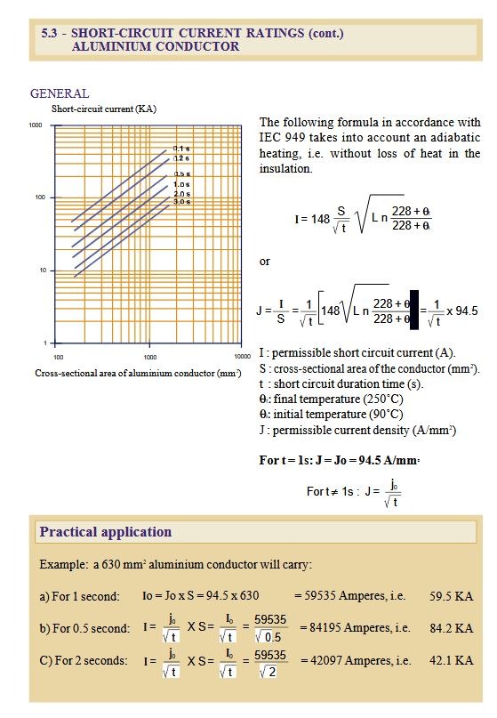
The cornerstone of IEC 60949 calculations is the adiabatic heating assumption. This thermal model presumes that during short-circuit events—typically lasting between 0.1 and 3 seconds—heat generated within the conductor remains entirely contained, with negligible heat loss through insulation or to surrounding environments. While this represents a simplified scenario compared to actual conditions, it provides a conservative and practical basis for design calculations.
Under adiabatic conditions, all energy dissipated by the fault current converts directly to temperature rise within the conductor material. This assumption proves remarkably accurate for short-duration faults because thermal energy transfer requires time. The insulation surrounding conductors acts as a temporary barrier, preventing rapid heat dissipation during the brief fault period. For durations beyond several seconds, heat transfer becomes more significant, and the adiabatic model incorporates inherent safety margins.
The standard establishes two critical temperature parameters: an initial temperature (θ_i) of 90°C and a final temperature (θ_f) of 250°C. The 90°C initial value represents the maximum continuous operating temperature for typical insulated conductors under normal load conditions. The 250°C final limit ensures that aluminium conductors remain below temperatures that could cause annealing, mechanical property degradation, or insulation damage. These temperature limits are carefully chosen to balance conductor thermal capacity with material integrity preservation.
Decoding the IEC 60949 Formula for Aluminium Conductors
The primary formula for calculating permissible short-circuit current in aluminium conductors is:
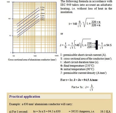
I = 148 · S · √( ln( (228 + θ_f) / (228 + θ_i) ) / t )
Each component of this equation serves a specific purpose. The constant 148 is an aluminium-specific factor derived from the material's electrical resistivity, thermal capacity, and density. This coefficient differs from the value used for copper conductors (approximately 226), reflecting aluminium's distinct physical properties.
The conductor cross-section (S) measured in square millimeters directly multiplies the result, acknowledging that larger conductors can carry proportionally higher fault currents. The logarithmic temperature ratio term captures the relationship between initial and final temperatures, while the constant 228 represents a reference point related to aluminium's temperature coefficient of resistance.
The square root relationship with duration (t) reveals a fundamental principle: current density calculation shows that permissible current increases as fault duration decreases. This inverse relationship stems from the thermal inertia of conductor materials—shorter fault periods allow less time for temperature rise, enabling the conductor to withstand higher current densities.
Current Density: A Practical Design Parameter
Rather than calculating total current repeatedly, engineers often work with current density (J), measured in amperes per square millimeter:
J = I / S = 148 · √( ln( (228 + θ_f) / (228 + θ_i) ) / t )
For standard conditions with θ_i = 90°C and θ_f = 250°C, the logarithmic term evaluates to ln(478/318) = 0.405. At a reference duration of one second, this yields a baseline current density:
J₀ = 94.5 A/mm²
This simplified approach allows engineers to quickly calculate short-circuit ratings using:
J = J₀ / √t and I = (J₀ / √t) · S
This current density baseline represents a critical reference point in cable sizing and short-circuit protection design. Understanding this value enables rapid assessment of conductor adequacy for specific fault level requirements.
Step-by-Step Calculation: The 630mm² Aluminium Conductor Example
Consider a practical scenario involving a 630mm² aluminium conductor, a common size in medium-voltage distribution systems and large industrial installations. Using standard temperature limits, we can determine short-circuit current ratings at various fault durations.
For t = 1.0 second: I₀ = J₀ · S = 94.5 A/mm² × 630 mm² = 59,535 A = 59.5 kA
This represents the one-second short-circuit current rating. If protective devices clear the fault within one second, the conductor can safely withstand nearly 60 kiloamperes without exceeding thermal limits.
For t = 0.5 seconds: I = I₀ / √0.5 = 59,535 / 0.707 = 84,195 A = 84.2 kA
The shorter duration permits a significantly higher current—approximately 41% greater than the one-second rating. This relationship between short-circuit duration and current rating is critical for coordinating protective devices with conductor capabilities.
For t = 2.0 seconds: I = I₀ / √2 = 59,535 / 1.414 = 42,097 A = 42.1 kA
Longer fault durations reduce permissible current levels. A two-second fault allows only about 71% of the one-second rating, demonstrating the importance of fast-acting protective equipment in systems with high fault levels.
Practical Application Scenarios
High-Power Distribution Systems
In large commercial buildings and industrial facilities, aluminium conductors often serve as main feeders and distribution buses. Consider a manufacturing plant with a 11kV/400V transformer rated at 2500 kVA. The calculated fault level at the secondary bus might reach 65 kA. Using IEC 60949 aluminium conductor calculation, engineers must select conductor sizes that withstand this fault current for the circuit breaker's operating time, typically 0.3 to 1.0 seconds.
For a 0.5-second clearing time and 65 kA fault level, the minimum conductor cross-section would be: S = I · √t / J₀ = 65,000 × √0.5 / 94.5 ≈ 487 mm²
Standard sizing would specify 500mm² or 630mm² conductors, providing adequate safety margin while optimizing material costs.
Data Center and Critical Infrastructure
Data centers demand exceptional reliability and often employ parallel conductor arrangements. When calculating short-circuit current density for multiple parallel conductors, engineers must account for current sharing and ensure each conductor's rating meets requirements. A typical scenario might involve four parallel 240mm² aluminium conductors supplying a 2000A busway system. Each conductor must individually satisfy short-circuit withstand requirements based on the total system fault level divided by parallel paths.
Renewable Energy Installations
Solar photovoltaic installations and wind farms increasingly utilize aluminium conductors for medium-voltage collection systems. These applications present unique challenges: varying ambient temperatures, outdoor installations with enhanced cooling, and potential for sustained fault conditions during grid disturbances. Engineers must carefully consider whether standard adiabatic assumptions remain valid or if adjusted temperature limits are warranted.
Addressing Common Design Challenges
Question 1: How to Calculate Short-Circuit Current for Non-Standard Temperatures
Problem: A conductor operates in a high-temperature environment with an initial temperature of 105°C instead of the standard 90°C. How should calculations be adjusted?
Solution: When temperature limits differ from standards, engineers must recalculate J₀ using the general formula. For θ_i = 105°C and θ_f = 250°C:
ln((228 + 250) / (228 + 105)) = ln(478/333) = 0.363
J₀ = 148 × √(0.363 / 1) = 89.2 A/mm²
This reduced baseline reflects the conductor's diminished thermal capacity when starting from a higher temperature. Short-circuit ratings decrease proportionally, requiring larger conductor sizes or enhanced protective coordination.
Question 2: Coordination with Circuit Breaker Ratings
Problem: A 630mm² aluminium conductor has a calculated one-second rating of 59.5 kA, but the system fault level is 75 kA. Is this conductor adequate if a circuit breaker clears faults in 0.3 seconds?
Solution: Calculate the permissible current at 0.3 seconds: I = 59,535 / √0.3 = 108,700 A = 108.7 kA
The conductor's 0.3-second rating exceeds the 75 kA fault level, confirming adequacy. This demonstrates how short-circuit duration and current rating relationship enables optimal design without oversizing conductors.
Question 3: Aluminium Versus Copper Selection
Problem: When should designers choose aluminium conductors over copper for applications with high fault levels?
Solution: Aluminium offers distinct advantages: lower material cost (typically 50-70% less than copper), reduced weight (approximately 70% lighter for equivalent current-carrying capacity), and adequate short-circuit performance when properly sized. However, copper provides higher current density, requiring smaller cross-sections. The decision hinges on:
Space constraints: Copper's compact size suits confined installations
Weight considerations: Aluminium benefits aerial applications and long spans
Connection technology: Aluminium requires specialized terminations to prevent oxidation
Economic analysis: Initial cost versus lifecycle performance
For fault levels below 50 kA and durations under one second, properly sized aluminium conductors typically provide cost-effective solutions without compromising safety.
Question 4: Multiple Cables in Parallel
Problem: How should short-circuit calculations account for three parallel 400mm² aluminium conductors?
Solution: Each conductor must individually withstand its share of fault current. For balanced parallel arrangements:
Total rating = 3 × (94.5 / √t) × 400 = 113,400 / √t amperes
At t = 1.0 second: Total capacity = 113.4 kA
Individual conductor current = 113.4 / 3 = 37.8 kA each
Verify that protective devices and conductor terminations also meet these requirements. Unequal current sharing due to different cable lengths or impedances requires derating calculations.
Limitations and Safety Margins in Real-World Design
While the adiabatic model provides reliable results for typical short-circuit scenarios, engineers must recognize its limitations. Heat dissipation does occur during faults, particularly those exceeding two seconds. The model's conservative nature generally ensures adequate safety margins, but extreme conditions may warrant detailed thermal analysis using finite element methods or manufacturer-specific software tools.
Temperature non-uniformity within conductors, skin effect at high frequencies, and proximity effects in closely spaced configurations can influence actual current distribution. For critical applications or unconventional installations, consultation with cable manufacturers and reference to their tested ratings provides additional assurance.
Essential Takeaways for Electrical Design
Mastering short-circuit current rating formula for aluminium conductors empowers engineers to design safer, more economical electrical systems. The IEC 60949 standard's systematic approach, grounded in adiabatic heating principles and validated through extensive testing, provides confidence in cable sizing decisions across diverse applications.
Key principles to remember:
Always verify conductor ratings against system fault levels and protective device clearing times
Use standard temperature limits (90°C to 250°C) unless specific conditions dictate otherwise
Account for the inverse relationship between fault duration and permissible current
Apply appropriate safety margins in critical applications
Coordinate conductor ratings with upstream and downstream protective devices
By integrating these IEC 60949 aluminium conductor calculation methods into design workflows, electrical engineers ensure installations that protect both equipment and personnel while optimizing material investments and long-term reliability.
How to Reach Us
Get in Touch
SiteMap
Product Catalogue
Festoon Cable
Shore Power Cable




Scan to add us on WeChat