

Short-Circuit Current Ratings for Lead Metallic Screens According to IEC 60949: Complete Technical Guide
Learn short-circuit current ratings for lead metallic screens per IEC 60949 standard. Calculate permissible current with formulas, adiabatic heating assumptions & worked examples.
hongjing.Wang@Feichun
12/29/20258 min read
Introduction
Overview of Short-Circuit Protection in High-Voltage Cables
Short-circuit events represent one of the most severe electrical fault conditions in power distribution networks. When a short-circuit occurs, massive current surges flow through the cable system, generating intense heat that can permanently damage cable insulation, compromise structural integrity, and create safety hazards. In high-voltage cable installations, metallic screens serve as critical protective elements, providing both electromagnetic shielding and a controlled path for fault currents to safely dissipate.
The lead metallic screen, in particular, plays an essential role in cable short-circuit protection by conducting fault currents away from the primary conductor while maintaining the cable's electrical isolation. Understanding how to calculate permissible short-circuit current becomes paramount for ensuring system reliability and preventing catastrophic failures.
Why IEC 60949 Standards Matter
The IEC 60949 standard provides the internationally recognized methodology for determining short-circuit current ratings for cable metallic screens. This standard establishes a systematic framework for calculating the maximum current a lead screen can safely conduct during fault conditions without exceeding critical temperature limits. For engineers designing 64/110 kV cable systems and higher voltage applications, compliance with IEC 60949 ensures that cable installations can withstand anticipated fault currents while protecting insulation from thermal breakdown. The standard's adiabatic heating assumption offers a conservative, safety-oriented approach that simplifies calculations while maintaining robust protection margins.
Fundamentals of Short-Circuit Current Ratings
Definition and Key Concepts
A short-circuit current originates when an electrical fault creates a low-resistance path between conductors or between a conductor and ground. Phase-to-ground faults and phase-to-phase faults generate enormous current surges, often reaching tens of thousands of amperes, that persist until protective relays detect and isolate the fault. The current rating of a cable screen defines the maximum fault current magnitude the screen can safely conduct, while the thermal rating specifies the temperature limits the screen material can tolerate.
Current density calculation, expressed in amperes per square millimeter (A/mm²), provides a fundamental design parameter. This metric allows engineers to evaluate screen performance independent of absolute cross-section dimensions, enabling universal application across various cable sizes.
The Adiabatic Heating Assumption
IEC 60949 employs an adiabatic heating assumption, meaning the calculation presumes no heat loss occurs through the cable insulation during the fault event. This conservative approach treats the external environment as providing no cooling benefit, creating a safety margin in the design. In reality, some radial heat dissipation does occur, but by ignoring this effect, the standard ensures calculated ratings remain on the safe side.
This assumption delivers significant practical advantages. Engineers can perform straightforward calculations without requiring complex empirical heat transfer data or detailed thermal modeling of the installation environment. The simplified approach reduces design time while maintaining conservative safety margins that protect cable infrastructure.
Lead as a Screen Material
Lead metallic screens offer excellent thermal properties for fault current conduction. Lead's resistivity and thermal conductivity characteristics make it well-suited for managing the intense heating that occurs during short-circuit events. The material exhibits predictable behavior across the operating temperature range, from normal conditions at 80°C to maximum fault temperatures approaching 210°C.
Compared to copper or aluminum screens, lead provides a cost-effective solution for medium-voltage applications where its temperature tolerance and current-carrying capacity meet design requirements. The material selection balances adequate protection during fault conditions against material costs and installation considerations.
Critical Temperature Parameters
The IEC 60949 formula establishes two critical temperature limits. The initial temperature θ_i = 80°C represents the screen's normal maximum operating temperature under steady-state load conditions. The final temperature θ_f = 210°C defines the maximum safe limit—beyond this threshold, lead begins softening and cable insulation faces potential degradation.
This creates a maximum allowable temperature rise ΔT = 130°C during fault events. Staying within these bounds ensures the screen maintains structural integrity and the insulation system survives without permanent damage.
IEC 60949 Formula Explained
Primary Formula Derivation
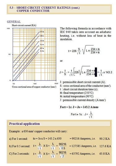
The IEC 60949 standard prescribes the following formula for calculating permissible short-circuit current in lead screens:
I = 41 · S · √[ln((230 + θ_f)/(230 + θ_i)) / t]
Where:
I = permissible short-circuit current (Amperes)
S = screen cross-section area (mm²)
t = fault duration (seconds)
θ_i = initial temperature before fault (°C)
θ_f = final temperature after fault (°C)
The constant 41 represents the IEC standard factor for lead screens, carrying units of A·s^½/mm². The constant 230 provides an empirical offset accounting for lead's resistance-temperature relationship across the operating range.
Current Density Formula
Dividing the permissible current by screen cross-section yields the current density:
J = I / S = 41 · √[ln((230 + θ_f)/(230 + θ_i)) / t]
This density-based calculation (A/mm²) offers significant utility because it applies universally regardless of actual screen size. Engineers can quickly evaluate whether a given fault scenario remains within safe operating bounds for any lead screen configuration.
Standard Temperature Limit Calculation
Substituting the typical temperature limits θ_i = 80°C and θ_f = 210°C into the logarithmic term:
ln((230 + 210)/(230 + 80)) = ln(440/310) = 0.35
This yields a reference current density:
J₀ = 41 · √(0.35/1) = 24.3 A/mm² at t = 1 second
This reference density provides a convenient starting point. For different fault durations, the relationship simplifies to:
J = J₀ / √t and I = J · S = (J₀ / √t) · S
Fault Duration Impact on Current Rating
The inverse square root relationship between fault duration and allowable current reveals critical design insights. A 2-second fault permits only 71% of the 1-second rating (I₂ = I₁/√2 ≈ 0.707·I₁). Conversely, a 0.5-second fault allows 141% of the 1-second rating (I₀.₅ = I₁/√0.5 ≈ 1.41·I₁).
This non-linear decay emphasizes the importance of rapid fault clearing. Protection systems with faster response times enable higher fault current capacity, providing greater operational flexibility and enhanced protection coordination possibilities.
Worked Example: 300 mm² Al 64/110 kV Cable with 400 mm² Lead Screen
Cable and Screen Specification
Consider a practical installation: a 64/110 kV medium-high voltage cable with a 300 mm² aluminum conductor protected by a 400 mm² lead metallic screen. The screen operates under standard temperature constraints with θ_i = 80°C representing normal operating conditions and θ_f = 210°C marking the maximum permissible fault temperature.
Step-by-Step Calculation
For t = 1.0 second (standard reference):
I₀ = J₀ · S = 24.3 A/mm² × 400 mm² = 9,720 A = 9.7 kA
This establishes the baseline: the lead screen can safely conduct 9.7 kiloamperes for one second without exceeding temperature limits.
For t = 0.5 second (faster protection):
I = I₀ / √0.5 = 9,720 / 0.707 = 13,746 A = 13.7 kA
With faster fault clearing—perhaps from high-speed relay protection responding within 0.5 seconds—the screen tolerates 41% higher current. This demonstrates how coordinated protection schemes enabling rapid response expand the cable's fault-handling capability.
For t = 2.0 seconds (slower protection):
I = I₀ / √2 = 9,720 / 1.414 = 6,873 A = 6.9 kA
If backup protection operates with a 2-second delay, the allowable current drops to approximately 71% of the 1-second rating. System designers must ensure maximum anticipated fault currents remain below this reduced threshold when slower protection schemes are employed.
Analysis and Practical Application
This example illustrates the critical interplay between protection system response time and cable current capacity. Engineers coordinating protection schemes must carefully match relay settings to cable thermal limits. The lead screen cross-section must adequately handle expected fault currents given the actual protection system's clearing time.
Prudent design incorporates appropriate safety margins, accounting for measurement uncertainties, relay tolerances, and potential protection system delays. The calculated values represent theoretical maximums—actual installations typically apply derating factors to ensure reliable operation under all anticipated conditions.
Application Scenarios and Common Cable Issues
Typical Application Environments
Lead metallic screen cables following IEC 60949 guidelines find extensive use in utility distribution networks, industrial power systems, and renewable energy installations. The 64/110 kV voltage class commonly appears in urban distribution feeders, connecting substations to load centers. Mining operations, petrochemical facilities, and manufacturing plants deploy these cables where reliable fault protection is essential for maintaining continuous operations.
Wind farms and solar installations increasingly utilize medium-voltage cables with lead screens for collector systems and grid interconnection. The standard's robust thermal protection ensures these installations can handle fault conditions in remote locations where maintenance access may be limited.
Common Problems and Solutions
Problem 1: Inadequate Screen Cross-Section Selection
Question: How do I determine if an existing cable's lead screen can handle anticipated fault currents in my network?
Solution: Perform a system fault study to calculate maximum fault current magnitudes at the cable location. Using the IEC 60949 formula, verify the installed screen cross-section provides adequate rating given your protection system's clearing time. If the calculated permissible current falls below anticipated fault levels, options include: upgrading protection to faster response times, installing current-limiting devices, or replacing the cable with larger screen cross-section.
Problem 2: Protection System Coordination Challenges
Question: My backup protection has a 2-second delay, but the cable screen was sized assuming 1-second clearing. Is this acceptable?
Solution: Recalculate the permissible current using t = 2.0 seconds. The allowable current will be approximately 71% of the 1-second rating. Compare this reduced value against maximum fault current for backup scenarios. If backup fault current exceeds the 2-second rating, you must either: reduce the backup time delay, increase screen size, or implement additional current limitation to ensure the screen remains within thermal limits even during backup protection operation.
Problem 3: Elevated Operating Temperatures
Question: Our cables operate in a hot environment with ambient temperatures reaching 50°C. How does this affect short-circuit ratings?
Solution: Higher ambient conditions elevate the initial temperature θ_i beyond the standard 80°C assumption. If your cable operates at, say, 90°C under normal load, recalculate using θ_i = 90°C. This reduces the available temperature rise margin (ΔT decreases from 130°C to 120°C), consequently lowering permissible short-circuit current by approximately 8-10%. Document these adjusted ratings and ensure protection settings account for the reduced capacity.
Problem 4: Multiple Screen Materials in System
Question: Our network contains both lead-screened and copper-screened cables. Can I use the same calculation approach?
Solution: No—different screen materials require different IEC constants. Lead screens use the factor 41 and constant 230. Copper screens require different values specified in IEC 60949 for copper. Always verify which material-specific factors apply to each cable section. Maintain separate calculations and ratings documentation for each screen material type to ensure protection coordination accounts for their different thermal characteristics.
Advanced Considerations
Conservative Design Margins
The adiabatic assumption underlying IEC 60949 calculations deliberately errs on the conservative side. By assuming no heat dissipation, the formula may underestimate actual capacity by 10-20% in some installations. However, engineers should resist the temptation to exploit this margin. The conservative approach provides essential safety buffers against calculation uncertainties, installation variations, and aging effects that may degrade performance over the cable's service life.
Integration with Modern Protection Systems
Contemporary digital protection relays offer sophisticated fault detection and rapid response capabilities. Time-current characteristic curves programmed into these devices must align with cable thermal ratings derived from IEC 60949 calculations. Protection engineers should generate coordination curves plotting the cable's thermal damage boundary against relay operating characteristics, ensuring the protection always operates before the cable reaches thermal limits.
Smart cable systems with embedded temperature sensors enable real-time monitoring of actual screen temperatures during fault events. This technology allows validation of theoretical calculations and provides early warning if operating conditions approach design limits.
Conclusion
The IEC 60949 standard provides an essential framework for calculating short-circuit current ratings in lead metallic screen cables. Understanding the relationship between screen cross-section, fault duration, and temperature limits enables engineers to design robust high-voltage cable systems capable of safely withstanding fault conditions.
The reference current density of 24.3 A/mm² at one-second fault duration, combined with the inverse square root relationship to fault time, offers straightforward tools for cable selection and protection coordination. By carefully matching screen sizing to anticipated fault currents and protection system response times, engineers ensure cable thermal integrity during maximum fault conditions while maintaining regulatory compliance.
As power systems evolve with increasing renewable integration and digital protection capabilities, the fundamental principles established in IEC 60949 remain vital. Whether designing new installations or evaluating existing infrastructure, proper application of these thermal rating calculations protects both equipment and personnel while ensuring reliable power delivery.
How to Reach Us
Get in Touch
SiteMap
Product Catalogue
Festoon Cable
Shore Power Cable




Scan to add us on WeChat