
The Complete Guide to Mining Cables for Underground and Open Cut Operations in Australia
Choosing the right mining cable in Australia? This guide covers underground, open cut, and feeder cable types — including Type 209, 241, 441, and 450 — with full specs, applications, Australian Standards compliance, and real-world mine site context. Built for procurement and engineering teams.
hongjing.Wang@Feichun
6/1/202638 min read
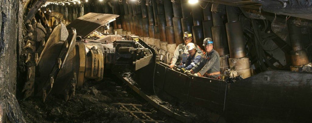
Whether you're sourcing cables for a longwall coal operation in the Hunter Valley, a dragline system at a Central Queensland open cut mine, or a primary feeder network at a metalliferous operation in Western Australia, getting your cable specification right is one of the most consequential decisions you'll make in the procurement cycle. The wrong choice leads to premature failures, unplanned downtime, safety incidents, and costly cable replacements mid-shift — all of which carry serious consequences in an industry where production losses are measured in tens of thousands of dollars per hour.
The Australian mining cable market is not a commodity segment. The cables used in underground coal mines, open cut dragline pits, and fixed underground power reticulation networks are purpose-engineered to meet a unique combination of regulatory, electrical, and mechanical requirements that simply do not exist in any other industry. They must comply with specific Australian and New Zealand Standards, withstand the mechanical abuse of continuous reeling and trailing service, provide integral earth fault protection through pilot conductor monitoring, and do all of this reliably across temperature extremes, chemical exposure, immersion conditions, and the kind of mechanical impact that would destroy a standard industrial flex in minutes.
This guide provides a comprehensive technical and application reference for the full range of mining cables relevant to Australian operations — underground trailing cables, open cut reeling cables, mine feeder cables, and machine wiring cables — with the depth of specification information that both procurement teams and electrical engineers need when making sourcing decisions.
The Regulatory Framework: What Australian Standards Apply to Mining Cables
Before diving into product specifics, it's worth understanding why mining cables in Australia form their own distinct product category rather than a subset of industrial or general power cables.
AS/NZS 1802 governs trailing cables used in underground coal mines. This standard is enforced through State and Territory mining regulations and imposes requirements that go well beyond what standard industrial cable standards require — including electrical symmetry requirements for underground coal cables (to ensure balanced capacitive coupling in gas-detection circuits), specific pilot conductor resistance limits, fire retardancy requirements, and requirements for the central extensible pilot conductor design that allows the integrity of the earth fault protection circuit to be continuously monitored.
AS/NZS 2802 covers trailing and reeling cables used in open cut mines and surface applications, again with requirements around pilot conductor design, mechanical performance, and fire retardancy that reflect the specific hazards of large open cut mining operations.
AS/NZS 1972 applies to mine feeder cables used in both underground and surface power reticulation, covering the higher-voltage, fixed or semi-fixed installation cables that form the primary distribution network throughout the mine.
AS/NZS 3008.1.1 provides the basis for current rating calculations referenced throughout this guide.
The Wiring Rules (AS/NZS 3000) apply as a baseline throughout Australian mining operations, but the mine-specific standards layer additional requirements on top of the general wiring rules. Local electricity authorities may also impose supplementary requirements, so procurement teams should always confirm applicable standards with their electrical engineer and, where relevant, with the relevant State or Territory mine safety regulator.
Cables must be installed by a licensed electrician with an appropriate licence for the State, Territory, or Country in question. This is not a technicality — it is a regulatory requirement, and non-compliant installation is a serious safety and legal exposure.
Understanding Cable Construction: The Building Blocks
Before working through the specific cable types, it's useful to understand the main constructional elements and what they contribute to cable performance, because the vocabulary appears throughout product specifications and understanding it helps you read a data sheet accurately.
Conductors
Mining cable conductors are almost universally tinned annealed copper wire, stranded to achieve the flexibility needed for reeling and trailing service. The number of individual wires, their diameter, the lay length of bunches and strands, and the geometric arrangement of the strands all affect flexibility and fatigue life. A simple visual comparison of wire count is not a reliable guide to flexibility or endurance — the lay ratio and geometric design matter as much as the number of wires. For heavy-duty reeling applications like longwall shearers or ship loaders, conductor designs are specifically engineered for the flex cycle duty involved.
The core assembly lay length is a particularly critical parameter for reeling cables. The ratio of cable lay length (pitch) to pitch circle diameter is commonly used to specify lay lengths for different duty ratings — for moderate duty reeling, this value should be less than 12.5, and for trailing cables it should be less than 17. Cables that exceed these ratios are more prone to conductor fatigue when subjected to repeated bending under tension.
Insulation
Natural rubber insulation has been largely replaced in mining cables by synthetic polymeric compounds offering superior performance. EPR (ethylene-propylene rubber) — specifically in copolymer (EPR) and terpolymer (EPDM) formulations — is the dominant insulation material in Australian mining flexible cables. EPR offers excellent thermal durability, outstanding corona resistance (important at medium voltages), and electrical characteristics that remain stable across the temperature and humidity ranges encountered in mines.
The specific grade used in most underground and open cut mining cables is R-EP-90, denoting an EPR compound rated to 90°C maximum conductor temperature. Some Class 1 open cut cables use XR-EP-90, a cross-linked EPR variant.
XLPE (cross-linked polyethylene) insulation is used in fixed-installation mine feeder cables, where its superior dielectric properties and 90°C temperature rating make it the modern standard for armoured feeder cable applications.
Semiconductive Screens
Two types of screening systems appear in mining cables, and the choice between them affects flexibility, earth fault performance, and application suitability.
Composite screens consist of a helically applied combination of tinned annealed copper wire and polyester yarn over the power core. These screens provide a well-defined metallic earth path and are mechanically robust, but are somewhat less flexible under repeated bending than semiconductive rubber alternatives. They're the standard choice for feeder and general trailing applications.
Semiconductive elastomer screens use a conductive rubber compound to screen the power cores, with separate earth conductors in the cable interstices (the spaces between the laid-up cores) providing the earth path. This construction is more flexible under repeated bending and is preferred for continuous miner cables, longwall shearer cables, and other high-flexing applications. Australian cables are required to have fire propagation-resistant semiconductive screens.
The semiconductive screen approach requires that the system be capable of limiting earth faults to around 500 mA (rms) within about 10 ms — a system design requirement that must be verified at the switchgear level, not just the cable level.
Pilot Conductors
The pilot conductor is a fundamental safety element of Australian underground mining cables, and understanding its function helps explain some specification decisions that might otherwise seem puzzling.
Mining equipment is typically isolated from earth by high resistance, meaning dangerous voltages can be present on equipment frames in fault conditions. To control this hazard, Australian underground mines use neutral resistance grounding systems. The integrity of this earth fault detection circuit is continuously monitored by passing a small independent current through the pilot conductor to the load centre and returning it through the earth conductor. If this current is interrupted — due to a broken conductor, a disconnected cable, or a damaged joint — the circuit breaker automatically trips and removes power from the circuit.
For this reason, Australian mining regulatory authorities require the inclusion of an extensible central pilot conductor in underground coal mining cables. The extensible design means the pilot can stretch slightly without breaking when the cable is under tension, while the central location makes it the last conductor to fail in an overloaded or overstretched cable. The cores of each underground coal mining cable must also be electrically symmetrical, ensuring that the capacitive coupling from phase conductors to earth is balanced — an important consideration for the correct operation of the neutral resistance grounding system.
Single-pilot cables (Types 209, 241, 241SF, 245SF, 409, 441) carry one central pilot. Three-pilot cables (Types 240, 440) carry three pilots located in the interstitial spaces. The choice depends on the cable length and the resistance limits imposed by the protection system — for long runs, three smaller pilots in parallel achieve a lower total resistance than a single central pilot.
Sheaths
The cable sheath is the outer mechanical and environmental barrier. The principal materials used in Australian mining cable sheaths are:
Polychloroprene (PCP) — the standard sheathing compound for most underground and open cut mining cables. PCP offers excellent resistance to oils, chemicals, and weathering, good mechanical strength, and adequate fire retardancy. Heavy-duty grades (HD-85-PCP) offer higher tensile strength and better tear resistance than standard grades.
Chlorosulphonated polyethylene (CSP) and Chlorinated polyethylene (CPE) — alternative synthetic polymers used in specific applications, offering improved chemical resistance in some environments.
XHD-85-PCP (Extra Heavy Duty) — used on Class 1 open cut high-voltage reeling cables (Types 450, 451, 455) where the combination of mechanical abuse and higher voltage requires the most robust sheath compound available.
Polyaramid (Kevlar) braid reinforcement — an optional or standard feature on many open cut trailing cables, incorporated into the sheath to dramatically improve cut-through and tear-propagation resistance. At open cut mines where cable runs cross over haul road edges, through rock debris, or under dragline tracks, the Kevlar reinforcement makes a measurable difference to cable service life.
Underground Mine Cables: Detailed Technical Reference
Type 209 — Composite Screened General Purpose Underground Cable (1.1–11 kV)
The Type 209 is the most versatile and widely deployed cable in the Australian underground mining sector. Built to AS/NZS 1802, it covers voltage ratings from 1.1/1.1 kV through to 11/11 kV in four variants designated by suffix: Type 209.1 (1.1 kV), Type 209.3 (3.3 kV), Type 209.6 (6.6 kV), and Type 209.11 (11 kV).
The cable construction consists of tinned copper three-phase power cores plus a central extensible pilot, EPR insulation (R-EP-90), composite screen (earth) of tinned annealed copper wire and polyester yarn, and a heavy-duty HD-85-PCP sheath. At 1.1 kV, the insulation tape is proofed textile; at 3.3 kV and above, a semiconductive tape is applied as both the conductor separator and the insulation screen, improving voltage stress distribution at the conductor surface.
Typical applications: Feeder connection between transformer and gate-end box, feeder cables to underground pumps, fans, and crushers. Also used as a substitute for Type A or B feeder cables and can be used above ground for power supply to mobile equipment.
Conductor size range: 10 mm² to 300 mm² across all voltage variants.
Representative specifications at 1.1 kV (Type 209.1):
A 35 mm² conductor has nominal insulation thickness 1.6 mm, AC resistance at 90°C of 0.698 Ω/km, 3-phase voltage drop of 1.22 mV/A.m, approximate screen area 14 mm², sheath thickness 4.6 mm, nominal overall diameter 43.6 mm, approximate mass 335 kg/100 m.
A 185 mm² conductor reaches a nominal diameter of 76.5 mm and mass of 1,155 kg per 100 m.
A 300 mm² conductor at 1.1 kV has a nominal overall diameter of 94.3 mm and weighs approximately 1,790 kg per 100 m.
Representative specifications at 3.3 kV (Type 209.3):
A 95 mm² conductor has AC resistance 0.271 Ω/km, 3-phase voltage drop 0.502 mV/A.m, nominal diameter 66.4 mm, mass 765 kg/100 m.
A 240 mm² conductor has nominal diameter 89.6 mm, mass 1,555 kg/100 m.
Representative specifications at 11 kV (Type 209.11):
A 95 mm² conductor has insulation thickness 7.6 mm, nominal diameter 93.8 mm, mass 1,360 kg/100 m.
A 240 mm² conductor at 11 kV presents a nominal diameter of 116 mm and mass of 2,280 kg per 100 m — a drum weight that requires crane or counterbalanced forklift handling at the mine site.
Pilot resistance: Maximum DC resistance is 5.5 Ω/100 m for power cores up to 35 mm²; 3 Ω/100 m for conductors above 35 mm². These limits are critical for protection system compliance.
The Type 209 is the default first choice for most underground coal feeder applications in Australia. Its composite screen construction gives it a clear and well-defined earth path, its approvals under both AS/NZS 1802 and AS/NZS 5000.1 cover the widest range of applications, and the range of conductor sizes and voltage variants means it can be standardised across a mine's cable inventory for multiple duties.
Type 210 — Composite Screened Hand-Held Equipment Cable (1.1 kV)
The Type 210 is a 1.1/1.1 kV composite screened cable designed specifically for hand-held boring machines and as a flexible lead to equipment where heavy-duty service is required in the most demanding hand-operated applications. It shares the same basic construction as the Type 209 — tinned copper cores, EPR insulation, composite screen, HD-85-PCP sheath — but is specified in the smaller conductor sizes suited to hand-held power tools.
Available in 1.5 mm² and 2.5 mm² conductor sizes. The 1.5 mm² variant (1.5-210-1) has an AC resistance at 90°C of 17.5 Ω/km, 3-phase voltage drop of 30.3 mV/A.m, nominal diameter 25.6 mm, and approximate mass 100 kg/100 m. The 2.5 mm² variant (2.5-210-1) reduces resistance to 10.5 Ω/km with a nominal diameter of 26.8 mm.
An important compliance note: certain regulatory authorities in Australia limit the use of this cable to 250/250V rather than the full 1.1/1.1 kV rating. Always confirm with the relevant State or Territory mine safety authority before specifying this cable for any hand-held tool application in your jurisdiction.
Type 240 — Three-Pilot Composite Screened Underground Cable (1.1–11 kV)
The Type 240 addresses a specific operational challenge encountered on large Australian underground mines: the resistance limitation of a single central pilot conductor over long cable runs. On a deep underground coal mine in NSW or Queensland where the distance from the surface substation to the working section gate-end box might be several hundred metres, a single pilot conductor — even at the 3 Ω/100 m limit — can accumulate enough total resistance to compromise the earth fault monitoring system's sensitivity.
The solution is three separate pilot conductors located in the interstitial spaces of the cable lay-up (rather than a single central one), reducing the total pilot circuit resistance to approximately one-third of the single-pilot value for the same conductor cross-section. The three pilots are elastomer-covered and proofed-taped, disposed in the cable interstices between the phase cores.
In other respects, the Type 240 shares its construction with the Type 209: tinned copper three-core power assembly, EPR insulation, composite screen, HD-85-PCP sheath with optional reinforcement. It covers 1.1/1.1 kV to 11/11 kV in the same .1, .3, .6, and .11 voltage variants.
Typical applications: Long underground feeder runs between transformer and gate-end box, continuous miner cables, feeder cables to pumps where single-pilot resistance would exceed system design limits.
Conductor size range: 6 mm² to 300 mm².
For applications requiring high degrees of flexibility in service, the Type 241 series is recommended instead. The Type 240's composite screen construction, while mechanically robust, does not offer the flex cycle endurance of the semiconductive elastomer screen used in the 241 family.
At 3.3 kV with a 185 mm² power conductor (185-240-3), the cable presents an AC resistance of 0.137 Ω/km, 3-phase voltage drop of 0.288 mV/A.m, nominal diameter 82.3 mm, and mass of approximately 1,330 kg per 100 metres.
Type 241 — Semiconductive Screened Underground General Purpose Cable (1.1–11 kV)
The Type 241 is the standard flexible underground cable for continuous miners, feeder cables to underground pumps, and monorails supplying DCBs and longwalls. It replaces the metallic composite screen of the Type 209 and 240 with a semiconductive elastomer screen, delivering improved flexibility under repeated bending cycles while maintaining the earth fault protection function through three separate semiconductive elastomer-covered earth cores disposed in the cable interstices.
The phase cores use EPR (R-EP-90) insulation with core numbers durably printed at intervals under 300 mm on a black semiconductive insulation screen — a practical field identification feature that reduces termination errors in underground environments where core colour identification can be difficult under artificial lighting. The single central extensible pilot maintains pilot monitoring compliance.
The sheath construction is an open-weave reinforcement under heavy-duty HD-85-PCP, giving better mechanical toughness than a sheath applied directly over the core assembly.
Voltage variants: Type 241.1 (1.1 kV), Type 241.3 (3.3 kV), Type 241.6 (6.6 kV), Type 241.11 (11 kV).
Conductor range: 6 mm² to 300 mm² at 1.1 kV; 16 mm² to 300 mm² at 3.3 kV; 16 mm² to 300 mm² at 6.6 kV; 25 mm² to 240 mm² at 11 kV.
Representative specifications at 1.1 kV (Type 241.1):
35 mm²: AC resistance 0.698 Ω/km, voltage drop 1.22 mV/A.m, earth core area 6 mm² each, nominal diameter 42.0 mm, mass 310 kg/100 m.
120 mm²: AC resistance 0.210 Ω/km, voltage drop 0.397 mV/A.m, nominal diameter 62.9 mm, mass 745 kg/100 m.
240 mm²: nominal diameter 83.2 mm, mass 1,370 kg/100 m.
300 mm²: nominal diameter 90.8 mm, mass 1,670 kg/100 m.
Representative specifications at 3.3 kV (Type 241.3):
70 mm²: AC resistance 0.346 Ω/km, voltage drop 0.626 mV/A.m, nominal diameter 60.6 mm, mass 620 kg/100 m.
185 mm²: nominal diameter 78.5 mm, mass 1,190 kg/100 m.
Representative specifications at 11 kV (Type 241.11):
95 mm²: insulation thickness 7.6 mm, nominal diameter 89.7 mm, mass 1,180 kg/100 m.
185 mm²: nominal diameter 104 mm, mass 1,720 kg/100 m.
Pilot resistance: Same limits as Type 209 — 5.5 Ω/100 m for cores up to 35 mm², 3 Ω/100 m above.
The Type 241 is the preferred choice over the Type 209 wherever flexibility under service conditions is a design driver — continuous miners, monorail systems, and pumping stations that are frequently relocated as the mine advances all benefit from the improved flex-cycle endurance of the semiconductive screen construction.
Type 241SF — Super Flexible Semiconductive Screened Underground Cable (1.1–11 kV)
The Type 241SF is a performance variant of the Type 241, specifically designed for applications where the standard 241's flexibility is not sufficient. The SF designation reflects modifications to the conductor stranding and cable lay-up that maximise flexibility while maintaining the same electrical and mechanical protection characteristics. Cable stranding uses finer individual wire sizes in a modified geometric arrangement, and the lay-up pitch is optimised for maximum flex-cycle endurance.
Voltage variants: Type 241.1 SF, Type 241.3 SF, Type 241.6 SF, Type 241.11 SF.
Conductor range: 70 mm² to 300 mm² (the SF design is optimised for the larger conductor sizes where flexibility gains are most significant).
Representative specifications at 1.1 kV (Type 241.1 SF):
70 mm²: nominal conductor diameter 12.1 mm (slightly larger than standard due to modified stranding), AC resistance 0.346 Ω/km, nominal overall diameter 52.7 mm, mass 525 kg/100 m.
185 mm²: nominal conductor diameter 19.0 mm, nominal overall diameter 74.8 mm, mass 1,115 kg/100 m.
300 mm²: nominal overall diameter 91.2 mm, mass 1,715 kg/100 m.
At 3.3 kV (Type 241.3 SF):
120 mm²: nominal diameter 70.0 mm, mass 900 kg/100 m.
240 mm²: nominal diameter 86.2 mm, mass 1,485 kg/100 m.
At 11 kV (Type 241.11 SF):
95 mm²: nominal diameter 90.3 mm, mass 1,225 kg/100 m.
185 mm²: nominal diameter 104 mm, mass 1,765 kg/100 m.
The slightly larger nominal conductor diameters compared to the standard Type 241 are a function of the modified stranding — finer wires in a less compacted arrangement give more flexibility but a marginally larger conductor overall diameter.
Use the Type 241SF wherever the standard Type 241 would be subjected to flex cycles beyond its design endurance. Continuous miners that are walked frequently, pump cables at advancing headings, and feeder cables that are repeatedly repositioned as development moves forward are all candidates for the SF variant.
Type 245SF — Super Flexible Longwall Shearer Cable (1.1–3.3 kV)
The Type 245SF occupies a unique position in the underground cable range: it is specifically engineered for the cable chain environment of longwall shearers. Cable chains on modern longwall shearers impose extremely tight bending radii — often well below what general-purpose mining cables can tolerate without fatigue — and the cable goes through thousands of bending cycles over its operational life as the shearer makes cut after cut across the face.
Two specific design features differentiate the Type 245SF from the standard 241SF. First, the cable stranding and lay-up have been modified to operate within the tight bending radii typical of longwall cable chains. Second, it includes three central pilot conductors rather than one, supporting the multi-function monitoring systems on modern longwall shearers that require additional pilot circuits for machine status monitoring, communications, and control interlocking.
Voltage variants: Type 245.1 SF (1.1/1.1 kV) and Type 245.3 SF (3.3/3.3 kV).
Conductor range: 50 mm² to 150 mm².
Representative specifications at 1.1 kV (Type 245.1 SF):
50 mm²: AC resistance 0.523 Ω/km, voltage drop 0.927 mV/A.m, earth cores 8 mm² each, nominal diameter 49.7 mm, mass 425 kg/100 m.
95 mm²: nominal conductor diameter 13.8 mm, nominal overall diameter 60.3 mm, mass 675 kg/100 m.
150 mm²: nominal overall diameter 70.8 mm, mass 1,010 kg/100 m.
At 3.3 kV (Type 245.3 SF):
50 mm²: nominal diameter 57.4 mm, mass 525 kg/100 m.
120 mm²: nominal diameter 75.7 mm, mass 989 kg/100 m.
150 mm²: nominal diameter 77.4 mm, mass 1,098 kg/100 m.
Pilot resistance: Maximum DC resistance 3 Ω/100 m for all conductors — tighter than the single-pilot limit because the three pilots are used for monitoring functions beyond basic circuit integrity.
At a Bowen Basin longwall operation running a full face-advance system with a high-productivity shearer making multiple cuts per shift, cable chain fatigue is a real operational cost driver. The Type 245SF's specifically optimised construction for this duty has measurably extended cable chain life on Australian longwall operations.
Type 275 — Shuttle Car Cable (1.1 kV)
The Type 275 is purpose-built for shuttle car service — arguably the most mechanically demanding cable application in underground coal mining. Shuttle cars use high-speed reeling drums that reel and unreel cable continuously during the loading and tramming cycle. The combination of high reel speed, tension, repeated bending, and the inherent tendency of shuttle car cable to corkscrew under repeated torsional load creates a demanding failure environment that general-purpose mining cables cannot withstand for reasonable service periods.
The Type 275 addresses the corkscrewing problem specifically through its core assembly design: the non-individually screened power cores, three earth cores, and a single extensible pilot are laid up with a semiconductive elastomer fill and with a core assembly construction engineered to resist the torsional imbalance that causes corkscrewing. The open-weave reinforcement under the HD-85-PCP sheath further improves mechanical toughness.
Conductor range: 16 mm² to 50 mm².
Specifications at 1.1 kV:
16 mm²: AC resistance 1.58 Ω/km, voltage drop 2.74 mV/A.m, earth core area 4.5 mm², nominal diameter 31.8 mm, mass 170 kg/100 m.
25 mm²: nominal diameter 35.0 mm, mass 225 kg/100 m.
35 mm²: nominal diameter 39.0 mm, mass 285 kg/100 m.
50 mm²: nominal diameter 43.3 mm, mass 370 kg/100 m.
Pilot resistance: 5.5 Ω/100 m for conductors up to 35 mm²; 3 Ω/100 m for larger conductors.
Open Cut Mine Cables: Detailed Technical Reference
Type 409 — Class 2 Composite Screened Open Cut Trailing Cable (1.1–22 kV)
The Type 409 is the primary general-purpose trailing and reeling cable for Australian open cut mines, built to AS/NZS 2802 and covering voltage ratings from 1.1/1.1 kV to 22/22 kV. As the open cut counterpart of the underground Type 209, it shares the composite screened, single central pilot construction but is specified to Class 2 — using slightly heavier insulation and sheath radials to suit the greater mechanical exposure of open cut service.
The defining feature for all Type 409 cables above 50 mm² at 1.1 kV is the Kevlar polyaramid yarn braid reinforcement incorporated into the HD-85-PCP sheath. At an open cut coal mine in the Hunter Valley or an iron ore operation in the Pilbara, the cable is dragged across rocky, abrasive surfaces and is exposed to the mechanical edges of haul roads, overburden piles, and tracked equipment. The Kevlar reinforcement delivers substantially better cut-through and tear resistance than an unreinforced PCP sheath, translating directly into longer cable service life and lower replacement frequency.
Voltage variants: Type 409.1 (1.1 kV), Type 409.3 (3.3 kV), Type 409.6 (6.6 kV), Type 409.11 (11 kV), Type 409.22 (22 kV).
Conductor range: 6 mm² to 300 mm² at 1.1 and 3.3 kV; 16 mm² to 300 mm² at 6.6 kV; 25 mm² to 240 mm² at 11 kV; 35 mm² to 95 mm² at 22 kV.
Representative specifications at 1.1 kV (Type 409.1):
50 mm²: AC resistance 0.523 Ω/km, voltage drop 0.925 mV/A.m, earth screen area 14 mm², nominal diameter 49.1 mm, mass 430 kg/100 m.
150 mm²: nominal diameter 72.3 mm, mass 1,025 kg/100 m.
240 mm²: nominal diameter 88.3 mm, mass 1,555 kg/100 m.
300 mm²: nominal diameter 95.7 mm, mass 1,860 kg/100 m.
At 3.3 kV (Type 409.3):
95 mm²: AC resistance 0.271 Ω/km, voltage drop 0.502 mV/A.m, nominal diameter 66.5 mm, mass 765 kg/100 m.
240 mm²: nominal diameter 89.8 mm, mass 1,560 kg/100 m.
At 11 kV (Type 409.11):
70 mm²: insulation thickness 7.6 mm, nominal diameter 88.8 mm, mass 1,185 kg/100 m.
185 mm²: nominal diameter 108 mm, mass 1,900 kg/100 m.
240 mm²: nominal diameter 116 mm, mass 2,280 kg/100 m.
At 22 kV (Type 409.22):
35 mm²: insulation thickness 10.5 mm, nominal diameter 102 mm, mass 1,420 kg/100 m.
95 mm²: nominal diameter 115 mm, mass 1,870 kg/100 m.
Pilot resistance: 3 Ω/100 m for power cores up to 35 mm²; 2 Ω/100 m above 35 mm² — tighter limits than the underground equivalent, reflecting the higher continuous load duties typical of open cut equipment.
Type 440 — Class 2 Composite Screened Three-Pilot Open Cut Cable (1.1–22 kV)
The Type 440 is the three-pilot open cut equivalent of the underground Type 240, solving the same long-run pilot resistance compliance challenge in an open cut trailing cable configuration. On a large area open cut coal mine in the Bowen Basin where a dragline or blasthole drill might be operating several kilometres from the nearest feeder substation, the accumulated pilot resistance of a single-pilot trailing cable can exceed protection system design limits. The Type 440's three pilots in the cable interstices reduce total pilot resistance to around one-third of the single-pilot value.
The three pilots are elastomer-covered and proofed-taped, disposed in the cable interstices, with the sheath incorporating optional Kevlar reinforcement for improved mechanical endurance in open cut service conditions.
Voltage variants: Type 440.1 (1.1 kV) through Type 440.22 (22 kV).
Conductor range: 6 mm² to 300 mm² at lower voltages; 35 mm² to 95 mm² at 22 kV.
At 1.1 kV (Type 440.1):
95 mm²: AC resistance 0.271 Ω/km, voltage drop 0.498 mV/A.m, nominal diameter 59.5 mm, mass 695 kg/100 m.
240 mm²: nominal diameter 88.1 mm, mass 1,610 kg/100 m.
At 6.6 kV (Type 440.6):
150 mm²: nominal diameter 89.2 mm, mass 1,410 kg/100 m.
300 mm²: nominal diameter 109 mm, mass 2,275 kg/100 m.
At 11 kV (Type 440.11):
120 mm²: nominal diameter 98.7 mm, mass 1,565 kg/100 m.
185 mm²: nominal diameter 108 mm, mass 1,945 kg/100 m.
Type 441 (1.1 kV) — Class 2 Semiconductive Screened Open Cut Cable
The Type 441 at 1.1 kV is the semiconductive-screened general-purpose open cut trailing and reeling cable for lower-voltage surface applications. Three semiconductive elastomer-covered earth cores are located in the interstices, with one EPR-covered central extensible pilot conductor. Phase identification is by printed numbers on the black semiconductive insulation screen. The Kevlar-reinforced HD-85-PCP sheath is optional for this voltage variant.
Conductor range: 6 mm² to 300 mm².
Specifications at 1.1 kV:
35 mm²: AC resistance 0.698 Ω/km, nominal diameter 42.2 mm, mass 305 kg/100 m.
95 mm²: nominal diameter 57.6 mm, mass 620 kg/100 m.
185 mm²: nominal diameter 74.4 mm, mass 1,115 kg/100 m.
300 mm²: nominal diameter 89.4 mm, mass 1,680 kg/100 m.
Type 441 (3.3–22 kV) — Class 1 Semiconductive Screened Open Cut Cable
The higher-voltage Type 441 (covering 3.3 kV to 22 kV) is a Class 1 cable — meaning it uses lower insulation and sheath radial thicknesses compared to Class 2 equivalents. This gives a smaller overall diameter and lighter mass for a given conductor size, which is advantageous in reeling applications where cable drum capacity and the mechanics of the reeling machine impose limits on cable OD and mass. These cables are finished with the Kevlar braid sheath reinforcement as a standard feature.
The insulation shifts from standard EPR to XR-EP-90 (cross-linked EPR) and the sheath upgrades to extra heavy-duty XHD-85-PCP — appropriate for the higher electrical and mechanical demands of this voltage range in open cut service.
Voltage variants: Type 441.3 (3.3 kV), Type 441.6 (6.6 kV), Type 441.11 (11 kV), Type 441.22 (22 kV).
At 3.3 kV (Type 441.3):
50 mm²: AC resistance 0.523 Ω/km, insulation thickness 2.4 mm, nominal diameter 54.4 mm, mass 470 kg/100 m.
150 mm²: nominal diameter 71.3 mm, mass 965 kg/100 m.
300 mm²: nominal diameter 87.4 mm, mass 1,620 kg/100 m.
At 11 kV (Type 441.11):
70 mm²: insulation thickness 5.0 mm, nominal diameter 71.6 mm, mass 765 kg/100 m.
185 mm²: nominal diameter 87.2 mm, mass 1,320 kg/100 m.
300 mm²: nominal diameter 100 mm, mass 1,880 kg/100 m.
At 22 kV (Type 441.22):
50 mm²: insulation thickness 7.6 mm, nominal diameter 79.2 mm, mass 840 kg/100 m.
185 mm²: nominal diameter 99.8 mm, mass 1,580 kg/100 m.
240 mm²: nominal diameter 106 mm, mass 1,850 kg/100 m.
Type 450 — Class 1 Composite Screened High-Voltage Reeling Cable (3.3–33 kV)
The Type 450 is the primary cable for the highest-duty open cut reeling applications in Australia: draglines, electric shovels, excavators, wharf cranes, and other large materials handling equipment operating at 3.3 kV through to 33 kV. It is a Class 1 composite screened cable to AS/NZS 2802, using XR-EP-90 EPR insulation with semiconductive elastomer screening, a composite copper wire and polyester yarn screen under a semiconductive tape, an XHD-85-PCP extra heavy-duty sheath incorporating polyaramid Kevlar reinforcement, and two earth cores plus one pilot core in the interstices.
The XHD sheath and Kevlar reinforcement are non-negotiable at these voltage levels and mechanical duty ratings. On a multi-bucket excavator at a brown coal mine in Victoria's Latrobe Valley, or a large electric shovel at a hard-rock copper mine in South Australia, the cable is subject to a continuous reeling cycle under substantial tension and is exposed to the full range of mechanical hazards of open cut mining. An earth fault at 11 kV or above has catastrophic potential, making the combination of mechanical toughness and reliable electrical screening critical to safe operation.
Voltage variants: Type 450.3 (3.3 kV), Type 450.6 (6.6 kV), Type 450.11 (11 kV), Type 450.22 (22 kV). 33 kV is available on request.
Conductor range: 25 mm² to 300 mm² across the standard range.
At 3.3 kV (Type 450.3):
50 mm²: AC resistance 0.523 Ω/km, voltage drop 0.925 mV/A.m, screen area 9.3 mm²/phase, earth/pilot area 12 mm² each, nominal diameter 54.5 mm, mass 515 kg/100 m.
185 mm²: nominal diameter 76.5 mm, mass 1,225 kg/100 m.
300 mm²: nominal diameter 89.0 mm, mass 1,800 kg/100 m.
At 11 kV (Type 450.11):
70 mm²: insulation thickness 5.0 mm, nominal diameter 73.1 mm, mass 855 kg/100 m.
150 mm²: nominal diameter 85.2 mm, mass 1,315 kg/100 m.
300 mm²: nominal diameter 101 mm, mass 2,080 kg/100 m.
At 22 kV (Type 450.22):
95 mm²: insulation thickness 7.6 mm, nominal diameter 88.9 mm, mass 1,230 kg/100 m.
240 mm²: nominal diameter 108 mm, mass 2,035 kg/100 m.
Type 451 — Class 1 Composite Screened High-Voltage Reeling Cable with Reduced Pilot (3.3–33 kV)
The Type 451 is functionally identical to the Type 450 in its power core and screen construction, but uses a smaller pilot conductor size. It is specified for the same application base — draglines, shovels, excavators, wharf cranes, and large-scale materials handling — in situations where the protection system design accommodates the reduced pilot conductance. This can offer a marginal benefit in overall cable mass and drum capacity, which can be meaningful on very large equipment where the reeling drum size is constrained.
Voltage variants and conductor ranges match the Type 450. A 120 mm² Type 451 at 11 kV (120-451-11) has a nominal diameter of 80.7 mm and mass of 1,105 kg/100 m — practically identical to the corresponding Type 450.11, confirming that the difference is primarily in the pilot sizing rather than overall cable geometry.
Type 455 — Class 1 Semiconductive Screened High-Voltage Reeling Cable (3.3–11 kV)
The Type 455 covers the same 3.3 kV to 11 kV dragline and shovel application as the Type 450 series, but with semiconductive elastomer screening in place of the composite copper wire screen. This makes it functionally similar to the Type 455's relationship with the Type 450 as the Type 441 has with the Type 409 — a semiconductive alternative to a composite screened equivalent.
The absence of the composite insulation screen in the Type 455 (compared to the Type 450) results in a slightly different outer geometry for the same conductor size. The XHD-85-PCP sheath with Kevlar reinforcement is retained as a standard feature.
Voltage variants: Type 455.3 (3.3 kV), Type 455.6 (6.6 kV), Type 455.11 (11 kV).
Conductor range: 25 mm² to 150 mm².
At 3.3 kV (Type 455.3):
70 mm²: AC resistance 0.346 Ω/km, insulation thickness 2.4 mm, nominal diameter 56.9 mm, mass 585 kg/100 m.
150 mm²: nominal diameter 69.1 mm, mass 1,010 kg/100 m.
At 6.6 kV (Type 455.6):
95 mm²: nominal diameter 63.3 mm, mass 745 kg/100 m.
150 mm²: nominal diameter 72.0 mm, mass 1,055 kg/100 m.
At 11 kV (Type 455.11):
70 mm²: insulation thickness 5.0 mm, nominal diameter 69.8 mm, mass 775 kg/100 m.
120 mm²: nominal diameter 77.0 mm, mass 1,040 kg/100 m.
150 mm²: nominal diameter 81.3 mm, mass 1,215 kg/100 m.
Mine Feeder Cables: High-Voltage Fixed Power Reticulation
11/11 kV Paper Insulated Cable — Legacy Mine Power Networks
Three-core belted paper insulated cables (to AS1026 and AS/NZS 1972) have been the backbone of Australian underground mine power reticulation for decades. Paper insulated, lead alloy sheathed, bitumen bedded, galvanised steel wire armoured, and red PVC sheathed, these cables operate at a maximum conductor temperature of only 65°C — well below the 90°C rating of modern XLPE equivalents — and are classified as rigid installations.
At the 11/11 kV rating, conductor sizes run from 50 mm² sector to 500 mm² sector, with nominal overall diameters from 53.0 mm at 50 mm² to 92.2 mm at 500 mm². Current ratings in free air range from 120 A at 50 mm² to 481 A at 500 mm², with ground and duct ratings lower. The armour is designed to provide at least 50% conductance of the power conductor, giving a useful earth fault current path.
Paper insulated cables remain in service in many existing Australian underground mine power networks, particularly at older operations in the New South Wales coalfields and in Queensland where the installed base has not yet been fully replaced. However, for new installations and major cable replacement projects, XLPE armoured feeder cables are now the standard specification because of their higher temperature rating, greater current capacity for a given conductor size, and lower susceptibility to moisture ingress damage in the wet conditions common in underground mines.
Note: 12.7/22 kV XLPE cable can be used as a direct alternative to paper insulated feeder cable in most applications, with the temperature rating gain typically allowing one to two conductor size steps of reduction — representing meaningful cost, weight, and space savings on long underground feeder runs.
6.35/11 kV XLPE Copper Feeder Cable — Standard Underground and Surface Primary Supply
The 6.35/11 kV XLPE copper feeder cable (to AS/NZS 1972) is the modern standard for primary power supply at Australian underground coal mines, metalliferous mines, and industrial mining networks at 11 kV. XLPE insulated, screened with plain annealed copper wire, galvanised steel wire armoured, and PVC outer sheathed (red), these cables offer a 90°C conductor temperature rating and can be installed direct buried, in duct, in free air, or in trench.
The metallic screen uses plain annealed copper wire with a combined area designed for at least 50% conductance of the power conductor — meeting the earth fault current path requirement of the Australian standard. The outer sheath colour coding (red) is the Australian convention for mine application cables.
Conductor range: 25 mm² to 240 mm².
Key specifications:
50 mm² (50XFED3C11): nominal conductor diameter 8.2 mm, nominal overall diameter 56.3 mm, mass 539 kg/100 m, free air current rating (spaced) 210 A, ground direct buried 202 A, ground in duct 170 A.
95 mm² (95XFED3C11): nominal diameter 64.4 mm, mass 778 kg/100 m, free air spaced 312 A, ground direct buried 290 A.
150 mm² (150XFED3C11): nominal diameter 71.3 mm, mass 1,009 kg/100 m, free air spaced 400 A.
185 mm² (185XFED3C11): nominal diameter 79.5 mm, mass 1,286 kg/100 m, free air spaced 460 A.
240 mm² (240XFED3C11): nominal diameter 85.1 mm, mass 1,533 kg/100 m, free air spaced 529 A.
The short-circuit rating for a 240 mm² cable at 11 kV is 34.3 kA for 1 second — a figure relevant to switchgear and protection settings.
12.7/22 kV XLPE Copper Feeder Cable — Higher Voltage Primary Distribution
The 12.7/22 kV XLPE feeder cable follows the same constructional principles as the 6.35/11 kV variant — compacted circular copper conductors, extruded semiconducting screens, copper wire metallic screen, galvanised steel wire armour, red PVC outer sheath — but the increased insulation thickness for the 22 kV voltage class results in larger overall diameters and masses.
Conductor range: 35 mm² to 240 mm².
Key specifications:
70 mm² (70XFED3C22): nominal conductor diameter 9.8 mm, nominal overall diameter 70.4 mm, mass 776 kg/100 m, free air spaced 265 A, ground direct buried 247 A.
120 mm² (120XFED3C22): nominal overall diameter 79.4 mm, mass 1,110 kg/100 m, free air spaced 364 A.
185 mm² (185XFED3C22): nominal diameter 89.8 mm, mass 1,449 kg/100 m, free air spaced 465 A.
240 mm² (240XFED3C22): nominal diameter 95.1 mm, mass 1,699 kg/100 m, free air spaced 535 A.
Wire armour diameters for the 185 mm² and 240 mm² variants step up to 3.15 mm (from 2.5 mm at smaller sizes), reflecting the greater structural demand at larger cable masses.
Single Point Suspension Cables (Borehole Cables) — 11 to 33 kV
Single point suspension cables — known universally in the Australian industry as borehole cables — represent one of the more specialised cable designs in the mining sector and are particularly common in NSW and Queensland underground coal operations, as well as at deep metalliferous mines in Western Australia and South Australia.
The operating concept is simple but the engineering is demanding: a single suspension point at the mine surface supports the entire weight of the cable as it descends a vertical shaft or borehole, which at a deep mine may mean 400 to 600 metres or more of unsupported cable length. The cable must be self-supporting from this single attachment point without transmitting damaging torsional forces to the cable terminations or the cable structure itself.
This requirement drives the use of double-layer armour specifically engineered to resist torsion. A single-layer armoured cable under self-supporting tension will rotate as it stretches, applying torsional forces to the cable assembly. The double-layer arrangement, with the two layers wound in opposite directions at appropriate angles, creates a torsion-balanced structure that resists rotation under load.
Common feeder voltages are 6.35/11 kV and 12.7/22 kV to AS/NZS 1972 (for underground coal mines) and AS/NZS 1429.1 (for metalliferous mines). Optional elements that can be incorporated include earth cores (for additional earth fault current capacity) and fibre optic cables within the assembly (for communications and monitoring back to the surface).
The final cable design for a single point suspension application is installation-specific — the structural engineering must account for the actual suspended length, the cable mass per metre, the required electrical ratings, and the downhole environmental conditions (temperature, groundwater, any gas exposure). A 400-metre suspended cable at an operational metalliferous mine in Western Australia has very different design requirements from a 200-metre borehole supply at a NSW coal mine. Consultation with a specialist cable engineer is essential before specification.
Type A and Type B 1.1/1.1 kV Feeder Cables
Types A and B are EPR insulated, tinned copper wire screened, HD-85-PCP sheathed 1.1/1.1 kV feeder cables to AS/NZS 1972. Semi-flexible rather than fully flexible, they are designed for situations where the cable between a transportable substation and connected equipment needs to be moved regularly — when a substation is relocated as the mine advance progresses, for example — but does not see continuous reeling or trailing service.
Type A carries three pilot conductors in the cable interstices; Type B carries no pilots. Both types use individually screened power cores with a tinned copper wire screen over each phase, and a polyester conductor tape separator.
Conductor range: 16 mm² to 240 mm².
Type A specifications:
50 mm² (50TYPEA): three power cores plus three 2.5 mm² pilots, AC resistance 0.499 Ω/km, voltage drop 0.879 mV/A.m, nominal diameter 38.1 mm, mass 315 kg/100 m.
120 mm² (120TYPEA): nominal diameter 53.0 mm, mass 645 kg/100 m.
185 mm² (185TYPEA): nominal diameter 65.2 mm, mass 975 kg/100 m.
240 mm² (240TYPEA): nominal diameter 74.5 mm, mass 1,300 kg/100 m.
Type B specifications are virtually identical to Type A (the absence of pilots makes negligible difference to overall cable dimensions), with masses running 5 to 10 kg/100 m lighter across the range.
Type 1 1.1/1.1 kV Machine Cables
Type 1 cables are PVC insulated and PVC sheathed machine wiring cables to AS/NZS 1972, designed for the internal wiring of mobile equipment — continuous miners, shuttle cars, road headers, personnel transports, and similar underground machines. They are not fire retardant and require further mechanical protection when used in external (non-protected) installations.
Available in both individually screened (IS) and collectively screened (CS) versions, with 2, 3, 4, 6, 16, and 30 core arrangements from 1.5 mm² to 16 mm². Cables rated above 20 A are electrically symmetrical.
Representative IS variants: 10T1-IS-3C (10 mm², 3-core): nominal diameter 18.1 mm, mass 60 kg/100 m. 16T1-IS-4C (16 mm², 4-core): nominal diameter 24.3 mm, mass 110 kg/100 m.
Representative CS variants: 1.5T1-CS-16C (1.5 mm², 16-core): nominal diameter 18.8 mm, mass 55 kg/100 m. 1.5T1-CS-30C (1.5 mm², 30-core): nominal diameter 24.7 mm, mass 90 kg/100 m.
Type 2S and Type 2S.3 Machine Cables
The Type 2S range (AS/NZS 1972) replaces the PVC-based Type 1 with EPR insulation and CPE sheathing, delivering fire retardant performance and a minimum operating temperature of -25°C — making it suitable for external installations in underground coal mines without additional mechanical protection. It is otherwise used for the same applications as Type 1: wiring of mobile equipment including continuous miners, shuttle cars, road headers, and personnel transporters.
Type 2S covers 1.1/1.1 kV in both individually screened (IS) and collectively screened (CS) versions. Type 2S.3 extends the range to 3.3/3.3 kV for higher-voltage machine systems.
Both types are available in a wide range of multi-core arrangements. The 3-core-plus-3-pilot configurations (ending in 3C3P) are particularly widely used for equipment control wiring where the power supply and pilot monitoring functions are integrated in a single cable.
Representative Type 2S IS 1.1 kV variants:
16T2S-IS-3C3P (16 mm², 3-core 3-pilot): nominal diameter 23.5 mm, mass 110 kg/100 m.
35T2S-IS-3C3P (35 mm², 3-core 3-pilot): nominal diameter 29.5 mm, mass 190 kg/100 m.
50T2S-IS-3C3P (50 mm², 3-core 3-pilot): nominal diameter 33.4 mm, mass 245 kg/100 m.
Representative Type 2S.3 variants at 3.3 kV:
70T2S.3-IS-3C3P (70 mm², 3-core 3-pilot, 3.3 kV): EPR insulation 3.0 mm, nominal diameter 48.3 mm, mass 435 kg/100 m.
120T2S.3-IS-3C3P (120 mm², 3-core 3-pilot, 3.3 kV): nominal diameter 56.4 mm, mass 640 kg/100 m.
Collectively screened variants:
1.5T2S-CS-6C: nominal diameter 16.0 mm, mass 35 kg/100 m.
1.5T2S-CS-30C: nominal diameter 29.1 mm, mass 120 kg/100 m.
Technical Reference: Current Ratings, Derating Factors, and Installation Correction
Continuous Current Carrying Capacity — Free Air
Current ratings for elastomeric mining cables are calculated in accordance with IEC 60287 for the free air condition, based on a conductor temperature of 90°C and an ambient air temperature of 40°C. Where cables are exposed to direct sunlight, a solar radiation absorption coefficient of 0.8 and irradiance of 1,000 W/m² are applied, which meaningfully reduces the allowable current.
For open cut surface applications in Queensland and Western Australia — where cables run through blasthole drill pads, along shovel cable tracks, and across the pit floor — direct solar exposure is the norm rather than the exception. Using the shaded ratings for a cable that will actually be in direct sun for most of its service day will result in running the cable above its design conductor temperature, accelerating insulation ageing and reducing service life.
Representative ratings for open cut trailing cables in free air, protected from sun:
35 mm² conductor: 145 A (1.1 kV), 145 A (3.3 kV and above).
70 mm² conductor: 220 A (1.1 kV), 220 A (3.3 kV and above).
120 mm² conductor: 295 A (1.1 kV), 295 A (3.3 kV and above).
185 mm² conductor: 385 A (1.1 kV), 385 A (3.3 kV and above).
240 mm² conductor: 455 A (1.1 kV), 450 A (3.3 kV and above).
300 mm² conductor: 515 A (1.1 kV), 510 A (3.3 kV and above).
When exposed to direct sun, reduce these values by approximately 25–30% depending on conductor size and voltage rating.
Derating for Reeling Drums
When a cable is stored in multiple layers on a cylindrical drum — as is common for trailing cables not fully deployed — heat cannot dissipate as effectively from the inner layers. The allowable current must be reduced to prevent conductor overtemperature. The correction factors are:
One layer on a cylindrical drum: multiply by 0.85. Two layers: 0.65. Three layers: 0.45. Four layers: 0.35. These are not conservative guidance values — they are the factors needed to maintain the conductor within its 90°C temperature rating. Operating above these limits risks premature insulation ageing and eventual failure.
For radial (flat coil) drums, the factors are somewhat better: 0.85 for ventilated radial drums and 0.75 for unventilated. Understanding the actual drum configuration on your equipment is therefore a necessary part of cable current rating selection.
Ambient Temperature Correction
The base rating assumes 40°C ambient air temperature. To apply a correction factor for a different ambient:
At 15°C ambient (typical of an underground mine heading): multiply by 1.26. At 25°C (mild surface day): 1.15. At 45°C (summer afternoon in the Pilbara or Queensland open cut): 0.94. At 50°C: 0.88.
For underground coal mine applications where the ambient heading temperature is typically 20–25°C rather than 40°C, cables can be operated at meaningfully higher load currents than the standard free-air rating suggests — a significant advantage for continuous miner cables and longwall feeder cables where load current is high.
Bending Radii — The Critical Mechanical Specification
Minimum bending radius is one of the most commonly under-specified parameters in mining cable installations, and failure to observe it is a leading cause of screen wire breakage and insulation damage in reeling applications.
For 1.1/1.1 kV cables in free flexing applications, the minimum bending radius is 6 times the cable overall diameter. For permanent repeated reeling, this increases to 10 times. Passing over sheaves: 10 times. Cable chain: 5 times (the tight bending environment is specifically addressed by the Type 245SF's design). Festoon applications: 7 times.
For cables rated 3.3 kV and above, all these values increase: free flexing 10 times, permanent repeated reeling 12 times, passing over sheaves 15 times, cable chain 10 times, festoon 10 times.
These are minimum values. Where tension is high or where the cable is subject to torsional loading as well as bending, increasing the bending radius beyond the minimum provides additional protection against screen wire fatigue.
Cable Tension Limits
The maximum safe working tensile force for metric flexible conductors is 20 N/mm² when trailing. To calculate the maximum pulling tension, multiply the number of power cores by the conductor cross-sectional area, then multiply by 20 N/mm². Note carefully: earth cores, pilot conductors, and screen conductors are excluded from this calculation — only the power conductor cross-sections count.
For a trailing cable with three 95 mm² power conductors, the maximum pulling tension is 3 × 95 × 20 = 5,700 N, or 5.7 kN. For three 185 mm² conductors: 3 × 185 × 20 = 11,100 N, or 11.1 kN. For three 240 mm² conductors: 3 × 240 × 20 = 14,400 N, or 14.4 kN.
Where cables are being dragged (rather than simply tensioned), the maximum length that can be dragged from a single formed centre point is calculated as the maximum pulling tension divided by the product of 0.5 (coefficient of friction), the cable mass in kg/m, and 10. For suspended cables, the maximum suspended length is the pulling tension divided by the product of cable mass in kg/m and 9.8.
Exceeding the safe tensile limit permanently stretches the conductors, elongates the insulation, and puts the cable into a condition where subsequent mechanical stresses — particularly compression cutting during runovers — will cause premature insulation failure.
Australian Mine Site Context: Real Application Scenarios
Hunter Valley Open Cut Coal Mines — NSW
The Hunter Valley is home to some of Australia's largest open cut coal operations, including mines like Mount Thorley Warkworth, Bengalla, and Muswellbrook. These operations use a mix of draglines, shovels, blasthole drills, and large conveyors, with cable requirements spanning from 1.1 kV trailing cables on small ancillary equipment through to 33 kV dragline reeling cables on the largest walking draglines.
In this environment, cable sheath durability on trailing cables is a persistent maintenance concern. Cables drag across coarse overburden material and are exposed to the wheels and tracks of haul trucks and ancillary equipment. Operations in the Hunter Valley have found that the Kevlar-reinforced PCP sheath on Type 409 and Type 450/451 cables meaningfully extends cable service intervals compared to earlier non-reinforced designs, reducing the frequency of cable splicing operations and the associated electrical safety risk.
For the longwall sections of underground mines in the Hunter Valley (where underground and open cut workings exist in proximity), Type 241SF cables at 3.3 kV and Type 245SF cables for shearer applications are standard specification — the SF (super flexible) designation addressing the high cycle count that high-output longwall operations impose on shearer cables.
Bowen Basin — Central Queensland
Queensland's Bowen Basin is Australia's largest metallurgical coal province, with major operations including Caval Ridge, Goonyella Riverside, Moranbah North, and Oaky Creek. The combination of deep underground longwall operations and large area open cut mines creates a wide range of cable application requirements.
Long underground feeder runs are a characteristic challenge at several Bowen Basin underground operations, where the distance from surface substations to operating sections can approach or exceed a kilometre. This is the scenario where the Type 240's three-pilot arrangement becomes important: at 1 km of cable run, a single central pilot in a Type 209 or Type 241 will accumulate 30 Ω total resistance at 3 Ω/100 m — which may exceed the maximum allowable pilot resistance for the earth fault protection system at the mine's neutral resistance grounding design current.
Surface temperatures in the Bowen Basin regularly exceed 40°C in summer, meaning that ambient temperature derating is required for cable ratings on surface-installed open cut cables — particularly those on draglines and blasthole drills that operate through the summer months without shade.
Pilbara — Western Australia
The Pilbara iron ore operations — at mines including Roy Hill, Brockman, and Hope Downs — are predominantly open cut and use large electric shovels and conveyors operating at medium voltages. The extreme summer temperatures (ambient air temperatures exceeding 45–50°C in hot weather at surface) mean that cable current ratings for open cut trailing cables must be derated from the 40°C base values, with the 45°C ambient factor of 0.94 representing a meaningful reduction in allowable load current.
UV exposure at surface installations in the Pilbara is severe. While the PCP and CPE sheathing compounds used in mining cables have good inherent weathering resistance, cables that are left on ground surface for extended periods without being rolled to redistribute sun exposure will suffer asymmetric UV degradation. Following the storage recommendation of rolling drums 90° every three months applies equally to deployed but temporarily stationary cables in these environments.
Borehole supply cables are used at several deep underground metalliferous mines in WA, including at operations in the Eastern Goldfields region. The self-supporting single point suspension design is critical at these locations where the mine geometry does not permit a conventional surface-to-working level power supply route.
Latrobe Valley — Victoria
Victoria's Latrobe Valley brown coal (lignite) mines — including Loy Yang and Hazelwood — operate large-scale bucket wheel excavators (BWEs), stackers, and reclaimers at voltages typically in the 3.3 kV to 11 kV range. The Type 455 semiconductive screened Class 1 reeling cable is the appropriate specification for BWE and stacker applications in this voltage range: it combines the flexibility needed for the continuous reeling of a large open cut machine with the mechanical protection of the XHD-85-PCP Kevlar-reinforced sheath and the Class 1 design that gives smaller overall diameters compared to Class 2 alternatives.
The softer, wetter terrain typical of Latrobe Valley operations means cable abrasion from rocky material is less of a concern than in hard-rock or coarse overburden open cut mines, but cable mechanical protection remains important given the scale and weight of the equipment involved.
Olympic Dam — South Australia
BHP's Olympic Dam operation at Roxby Downs is one of Australia's deepest underground mines, with workings extending hundreds of metres below the surface. The borehole power supply approach — using single point suspension cables to deliver primary power from the surface substation to underground distribution points — is used here to supply power to working levels without routing extensive cable installations through the shaft infrastructure.
The multi-layered torsion-balanced armour design of the borehole cable is specifically verified for the suspended lengths at Olympic Dam, where the cable engineering is site-specific to the actual shaft depth and cable mass involved.
Narrabri Coal Mine — NSW
Narrabri Coal, operated in the Gunnedah Basin of NSW, runs one of Australia's highest-productivity longwall operations. The longwall shearer cable environment at Narrabri is demanding: high shearer speeds, long face lengths, and high cutting advance rates mean the cable chain cycles through bending cycles at a rate that standard flexible cables cannot sustain for acceptable service intervals.
The Type 245SF at 3.3 kV is the specification suited to this application — the three-pilot arrangement supporting the shearer's monitoring system, the modified stranding and lay-up delivering the flex-cycle endurance needed at Narrabri's production rates, and the XR-EP-90 insulation maintaining electrical performance at the 3.3 kV operating voltage.
Procurement Guidance: Making the Right Specification Decision
Start With These Four Questions
Every mining cable specification should start with four fundamental questions, and getting the answers right before engaging with technical detail will avoid most common specification errors.
What is the voltage rating? Not the nominal system voltage alone, but the correct cable voltage designation. A 6.6 kV distribution system requires a cable rated at 3.8/6.6 kV minimum — the first number is the phase-to-earth voltage. For earthed neutral systems, check whether the cable needs to be rated for the full phase-to-earth voltage or whether a lower insulation level is permissible under the system's earth fault clearance time and method. The cable data sheets present voltage ratings as X/X kV — the first figure is phase to earth, the second is phase to phase.
What is the application category? Underground trailing/continuous miner, underground feeder (fixed or semi-fixed), open cut trailing/reeling, or open cut feeder. This determines which Australian Standard applies and which cable type families are relevant.
What is the mechanical duty? Single-pilot or three-pilot requirement (based on cable length and protection system design)? Slow reeling, moderate reeling, or arduous high-speed reeling? Cable chain, festoon, or direct trailing? The mechanical duty determines which cable type within a family is appropriate — Type 209 versus 240 for underground, Type 241 versus 241SF versus 245SF for flexibility requirements, Class 1 versus Class 2 for open cut high-voltage applications.
What are the current requirements? The required load current, including any derating for drum layers, ambient temperature, grouping with other cables, or solar exposure, determines the minimum conductor size. Undersizing the conductor creates overtemperature conditions that accelerate insulation ageing. Oversizing wastes cost, adds mass, reduces flexibility, and may create drum capacity problems on reeling applications.
Common Specification Errors to Avoid
Using underground cable type designations for open cut applications — and vice versa. Underground cables to AS/NZS 1802 and open cut cables to AS/NZS 2802 have different constructional requirements and are not interchangeable, even where the physical cable appears similar.
Ignoring the drum derating factor. It is surprisingly common for cable current ratings to be selected against the standard free-air rating without considering that the cable will spend part of its operational life partially coiled on its drum. For equipment where the cable is only partially deployed at any time — a dragline with 250 m of cable only using 150 m at maximum reach, for example — the remaining 100 m on the drum must be assessed for its derating impact.
Not checking pilot resistance compliance over the actual installed cable length. This is particularly important on long underground feeder runs and large-area open cut operations. Calculate the total pilot circuit resistance (using the maximum DC resistance value from the data sheet multiplied by the cable length in units of 100 m) and compare it against the maximum allowable value in the mine's earth fault protection system design. If it doesn't comply with a single-pilot cable, move to a three-pilot type before finalising the specification.
Selecting conductor size based on voltage drop alone without checking thermal rating. Voltage drop calculations using mV/A.m values can produce a conductor size that is thermally adequate in some conditions but not others. Always check both the voltage drop and the current rating, and apply all relevant derating factors to the current rating check.
Underestimating drum handling requirements for larger cables. A 300 mm² Type 241 cable at 11 kV weighs approximately 2,340 kg per 100 metres. A 200 m drum of this cable approaches 4,700 kg — a crane lift at the mine site, not a forklift operation. Check that the site's mechanical handling equipment is adequate for the drum mass before confirming the cable length and drum configuration.
Approvals Verification
Before purchasing, verify that the cable offered meets the approvals relevant to your application. Underground coal mine cables should carry AS/NZS 1802 approval; open cut cables should meet AS/NZS 2802; mine feeder cables should comply with AS/NZS 1972. For cables also used for general low-voltage power applications (as the Type 209 can be), AS/NZS 5000.1 approval may additionally be required.
Where a cable will be installed in a State or Territory that imposes supplementary requirements through mining safety legislation (as NSW and Queensland do for underground coal), confirm with the relevant regulator'
How to Reach Us
Get in Touch
SiteMap
Product Catalogue
Festoon Cable
Shore Power Cable




Scan to add us on WeChat