
Type 441 Class 1 Mining Cable: The Engineering Behind Australia's Most Demanding Trailing and Reeling Applications
Discover the engineering of Type 441 Class 1 AS/NZS 2802 mining cables — EPR insulation, PCP sheath, semiconductive cradle design — built for bucket wheel excavators and high-voltage trailing duties in Queensland's Bowen Basin coal mines.
hongjing.Wang@Feichun
3/11/202614 min read
Introduction: When a Cable Is the Lifeline of a Mine
Picture a bucket wheel excavator — a machine as tall as a fifteen-storey building, with a rotating wheel studded with steel buckets, chewing through overburden at thousands of tonnes per hour. At the Goonyella Coal Mine in Queensland's Bowen Basin, machines like these operate around the clock, feeding a continuous conveyor chain that feeds the world's steel mills with premium hard coking coal.
Now consider what keeps that excavator moving: a single trailing cable, coiling and uncoiling as the machine traverses the pit floor, dragged across coal dust and crushed rock, compressed under the weight of passing equipment, exposed to Queensland's punishing UV and temperature extremes. That cable is not an afterthought. It is a precisely engineered system — and in the Australian mining industry, the benchmark for this application is the Type 441 Class 1 mining cable, manufactured to AS/NZS 2802:2000.
This article examines the cable's construction layer by layer, explains the material choices and their engineering rationale, and sets out why this design is the preferred solution for high-voltage trailing and reeling duties across Australia's open-cut coal sector.
The Application Context: What Makes Mining Trailing Cables Different
Before dissecting the cable itself, it is worth understanding why standard industrial power cables are entirely unsuited to this application — and why the failure consequences are so severe.
A trailing cable on a bucket wheel excavator is not a static installation. It is a dynamic mechanical system. Over the course of a single shift, the cable may be wound and unwound from a drum dozens of times, bent through tight radii, subjected to lateral compression when it falls beneath conveyor frames or vehicle tyres, and twisted as the excavator rotates its superstructure. Throughout all of this, it must continuously deliver voltages ranging from 3.3 kV up to 22 kV without a single insulation breakdown.
A standard fixed-installation power cable would fail rapidly under these conditions. PVC insulation becomes brittle under repeated bending and cracks in low temperatures. Standard sheathing compounds abrade away on rock-covered ground. Fixed cables are not designed to be wound onto a drum at all — the mechanical stresses of repeated spooling fracture their insulation within weeks.
This is the engineering problem that Type 441 Class 1 is built to solve.
Construction Deep Dive: Layer by Layer
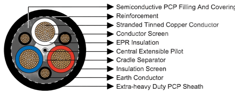
The Type 441 Class 1 cable is a multi-layer composite system. Each layer addresses a specific failure mode. Understanding the construction from the inside out reveals a coherent engineering philosophy: protect the insulation at all costs, maintain flexibility under all conditions, and provide multiple independent safety barriers.
The Conductor: Flexible Stranded Tinned Annealed Copper
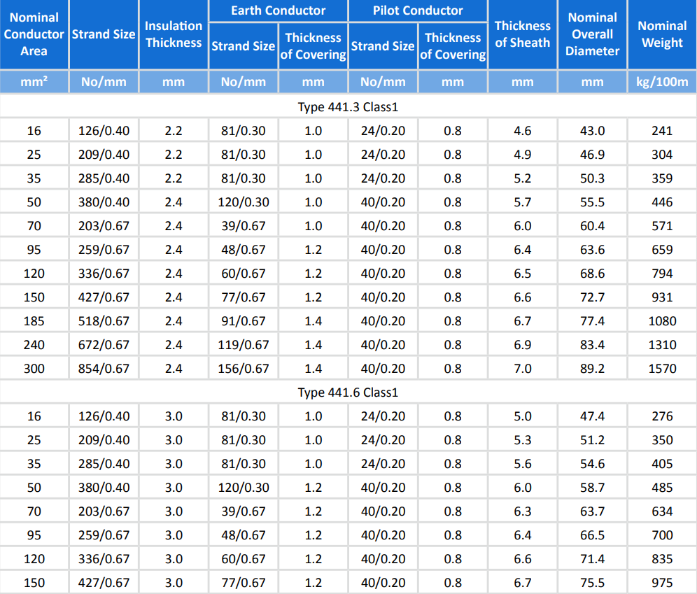
The foundation of the cable is a Class 2 flexible stranded conductor made from tinned annealed copper. The multi-strand construction — ranging from 126 strands for 16 mm² conductors up to 854 strands for 300 mm² conductors — is fundamental to the cable's flex life. Each individual strand is fine enough to bend without fatigue cracking under repeated flexing, and the aggregate of hundreds of strands creates a conductor that can absorb the cumulative mechanical work of thousands of reeling cycles without resistance increase or conductor fracture.
Tinning of the copper strands serves two purposes. It prevents oxidation at the strand surfaces, which would increase contact resistance and generate heat over time. It also improves solderability and compatibility with the semiconductive screening compounds that are applied directly over the conductor surface.
The Conductor Screen: Semiconductive Compound
For all cable variants rated at 3.3 kV and above, a semiconductive compound screen is applied over the conductor assembly. This is not an insulating layer — it is an equalising layer. The surface of a stranded conductor is geometrically irregular: the interstices between strands create microscopic voids and points of high electric field concentration. Without a conductor screen, these field concentrations would initiate partial discharge at the conductor-insulation interface, progressively degrading the insulation from the inside.
The semiconductive screen presents a smooth, equipotential surface to the insulation layer, eliminating geometric field irregularities. In a cable that will be bent and flexed repeatedly throughout its service life, this function is especially critical — mechanical deformation of the cable inevitably shifts the geometry of the conductor bundle, and the screen continuously compensates for these shifts by re-establishing a uniform field boundary.
The Insulation: EPR (Ethylene Propylene Rubber)
The choice of EPR as the primary insulation material is not arbitrary — it represents the outcome of decades of field experience in Australian mining environments, and EPR consistently outperforms PVC and XLPE in this application.
EPR's advantages begin with flexibility. Its elastic modulus is significantly lower than PVC, meaning the insulation deforms under bending stress and recovers elastically when the stress is removed, rather than accumulating fatigue damage through plastic deformation. In practice, EPR insulation can sustain hundreds of thousands of bending cycles without developing the hairline cracks that appear in stiffer materials.
Thermal performance is a second key advantage. EPR maintains its mechanical and electrical properties across a wide temperature range — from below -40°C, which exceeds the coldest Queensland winter temperatures at altitude, to 90°C continuous operating temperature. PVC, by contrast, begins to lose plasticiser and become brittle at sustained elevated temperatures, and it can crack in sub-zero conditions even without mechanical stress.
EPR's resistance to moisture, ozone, and ultraviolet radiation is also superior to PVC. An open-cut mine is a relentlessly hostile environment: cables lie in pooled water, are exposed to continuous UV radiation, and encounter ozone generated by electrical equipment. EPR's molecular structure — saturated polymer backbone with no double bonds susceptible to ozone attack — resists degradation in all of these conditions without the rapid surface crazing that characterises PVC in UV-exposed outdoor applications.
Insulation thicknesses for the Type 441 Class 1 series increase with voltage rating. At 3.3 kV, the insulation wall is 2.2 to 2.4 mm. At 6.6 kV it is 3.0 mm, at 11 kV it rises to 5.0 mm, and at 22 kV it reaches 7.6 mm. These thicknesses reflect the dielectric stress levels at each voltage and are validated through power-frequency withstand testing and partial discharge measurement in accordance with AS/NZS 2802:2000.
The Insulation Screen: Semiconductive Elastomer
Directly over the EPR insulation, a semiconductive elastomeric insulation screen is applied. This layer mirrors the function of the conductor screen at the outer insulation boundary — it creates a smooth equipotential surface that eliminates field concentrations at the insulation-screen interface and provides a defined outer boundary for the electric field within the insulation.
The continuity of this screen under repeated bending is critical. A screen that cracks or separates from the insulation surface creates a gas-filled void at the interface. Partial discharge occurs preferentially in such voids, eroding the insulation surface and eventually creating a conductive discharge channel through the insulation wall. The elastomeric formulation of this screen allows it to flex with the insulation and maintain intimate contact with the EPR surface across the entire range of cable deformation encountered in service.
The Cradle Separator: Semiconductive PCP
The cradle separator is one of the most distinctive structural features of the Type 441 Class 1 design, and it is largely responsible for the cable's resistance to the crushing and squashing damage that terminates the service life of lesser trailing cables.
After the three insulated and screened cores are laid up together, a semiconductive PCP (polychloroprene) cradle is formed around and between them. This cradle performs two related functions simultaneously. First, it mechanically supports and locates the three power cores, preventing them from migrating relative to one another under the repeated bending and compression of service. Core migration leads to uneven loading, localised bending stress concentration, and accelerated insulation fatigue.
Second, when the cable is subjected to external crushing loads — from a vehicle tyre, a conveyor structure, or a collapsed excavation wall — the cradle distributes the compressive force across the full cable cross-section rather than concentrating it on whichever core happens to be at the point of maximum load. Without this structure, crushing forces create point loads on individual cores that exceed the insulation's compressive strength and cause immediate dielectric failure.
The semiconductive nature of the PCP material ensures that the cradle also participates in the overall electromagnetic shielding system of the cable, providing continuity between the individual core screens and the overall screen applied over the assembled cores.
The Overall Core Screen: Semiconductive PCP Filling and Covering
Once the three cores and the cradle are assembled, the interstices of the construction are filled with semiconductive PCP compound, and a covering of the same material is applied over the complete assembly. This layer serves as the outer electromagnetic shield of the high-voltage system.
The filling compound eliminates air voids within the cable interior. Air-filled voids at medium voltage are sites of continuous partial discharge activity — the dielectric strength of air is orders of magnitude lower than that of solid polymer, and even small voids subjected to significant electric fields will sustain discharge activity that erodes surrounding insulation surfaces over time. Eliminating these voids through compound filling is therefore a direct life-extension measure.
The covering provides a defined equipotential surface over the entire assembled core group, to which the earth conductors and the sheath can be referenced. It also provides mechanical protection to the individual core screens during the subsequent manufacturing operations of laying up the earth conductors and applying the reinforcement and sheath.
The Earth Conductors: Three Symmetric Interstitial Conductors
Three earth conductors are positioned symmetrically in the interstices between the filled core assembly, covered with semiconductive PCP compound. These conductors are sized in proportion to the main power conductors — for example, a 16 mm² main conductor cable uses 81-strand / 0.30 mm earth conductors, while a 300 mm² cable uses 156-strand / 0.67 mm earth conductors.
The symmetric placement of three earth conductors serves electrical and mechanical purposes. Electrically, three conductors provide the current-carrying capacity required by AS/NZS 2802 for earth fault protection — in Australian mining practice, earth fault protection relays operate on earth conductor current, and the conductor must carry sufficient fault current to ensure relay operation before the fault escalates. Mechanically, symmetric placement balances the cable's bending stiffness profile, so that the cable does not preferentially bend in one plane and develop asymmetric fatigue stress patterns.
The Central Extensible Pilot Conductor: EPR-Covered and Centrally Located
The central pilot conductor is positioned at the geometric centre of the cable — the point of minimum bending strain during cable flexing. This is an important detail: if the pilot were positioned off-centre, it would experience the same bending strain as the power cores, potentially fatiguing before them and triggering protective shutdown prematurely.
The conductor is described as "extensible" — its actual laid length within the cable is slightly greater than the laid length of the power cores. This design ensures that when the cable is subjected to tensile loads during trailing and reeling operations, the power cores reach their strain limit and actuate the protective relay before the pilot conductor is mechanically damaged. The pilot conductor is thus the early-warning system of the cable: it signals the need for maintenance before catastrophic insulation failure can occur.
The EPR covering on the pilot conductor provides electrical insulation from the surrounding earth conductors and ensures the pilot circuit remains independent and reliable throughout the cable's service life.
The Textile Reinforcement: Open-Weave Braid
Over the complete cable assembly, an open-weave textile braid reinforcement is applied. This layer adds axial tensile strength to the cable without significantly increasing its bending stiffness — a critical balance in a trailing cable application. The open-weave construction allows the individual braid elements to slide relative to one another as the cable bends, so the reinforcement conforms to the deformed cable shape without creating a rigid shell that concentrates bending stress at the edges of the reinforced zone.
The reinforcement is particularly important during the dynamic phases of cable operation: when the cable is being paid out from a reel under tension, or when it is being pulled across the pit floor by a moving excavator. Without axial reinforcement, these tensile loads would be transferred entirely to the copper conductors, which are not designed to sustain significant tensile stress without elongation and resistance increase.
The Outer Sheath: Extra-Heavy-Duty PCP
The outermost layer of the Type 441 Class 1 cable is an extra-heavy-duty PCP sheath, with wall thicknesses ranging from approximately 4.6 mm for 16 mm² / 3.3 kV cables up to 7.6 mm for 185 mm² / 22 kV cables. For applications with specific chemical resistance requirements, an extra-heavy-duty CPE/CSP sheath is available as an alternative.
PCP is the standard of the Australian mining industry for heavy-duty cable sheathing, and for good reason. Its resistance to mineral oil is outstanding — hydraulic fluid leaks from excavator systems will not cause the sheath to swell, soften, or crack, a failure mode that rapidly compromises otherwise-intact cables. PCP's resistance to ozone and ultraviolet radiation prevents the surface crazing and longitudinal cracking that degrade natural rubber compounds in prolonged outdoor exposure. Its abrasion resistance under sliding contact with rock and coal is substantially better than that of NR/SBR blends.
Critically for mining applications, PCP is inherently flame-retardant. The chlorine content of the polymer backbone promotes char formation and self-extinguishing behaviour under direct flame impingement — when the ignition source is removed, the sheath ceases to burn. This property is mandated by Australian mining safety regulations and verified through standard combustion tests as part of AS/NZS 2802 compliance testing.
Class 1 vs Class 2: The Engineering Rationale for Thinner Walls
A question that frequently arises in cable selection is why AS/NZS 2802 defines two classes of reeling and trailing cable, and which class is appropriate for a given application. The distinction has important practical consequences for reeling applications.
Class 2 cables have thicker insulation and sheath walls than Class 1 cables at the same voltage rating. This additional material provides a larger dielectric safety margin and greater mechanical protection against abrasion and crushing — properties that are valuable in applications where cables are dragged continuously on highly abrasive surfaces without being coiled.
Class 1 cables, including the Type 441 Class 1, achieve equivalent electrical safety with thinner walls by relying on superior material quality and tighter dimensional control. The thinner construction has two direct benefits for reeling applications. First, the reduced overall diameter means the cable coils to a smaller drum radius for the same number of turns, reducing the mechanical stress on the insulation during bending onto the drum. Second, the reduced weight — which can be significant over the lengths involved in BWE trailing, sometimes hundreds of metres — reduces the dynamic load on the cable drum drive system, extending the life of both the drum mechanism and the cable itself.
The semiconductive PCP cradle separator compensates for the thinner walls by providing mechanical protection against crushing that an equivalent Class 2 cable without a cradle would not possess. The net result is a cable that is lighter and more flexible than Class 2, while providing superior protection against the specific failure modes — crushing and squashing — that are most prevalent in reeling applications.
Voltage Versatility: One Cable Family from 3.3 kV to 22 kV
The Type 441 Class 1 series covers the full range of voltages encountered in Australian open-cut mining operations. The 3.3/3.3 kV variant suits auxiliary equipment and lower-rated drive systems, with conductor sizes from 16 mm² to 300 mm². The 6.6/6.6 kV variant serves mid-range drive systems across the same conductor range. The 11/11 kV variant covers conductor sizes from 25 mm² to 240 mm², appropriate for high-power excavator main drives. The 22/22 kV variant, available from 35 mm² to 185 mm², addresses the highest-voltage applications found on the largest excavators and at primary power distribution points within the mine.
This voltage continuity within a single cable family simplifies inventory management for mine operators who run mixed fleets. A single procurement specification, a single set of installation procedures, and a single set of jointing and termination practices cover the entire voltage range — a meaningful operational advantage in a complex mining environment.
Applicable Equipment: Where Type 441 Class 1 Works
Bucket Wheel Excavators are the primary application for which the Type 441 Class 1 series is optimised. BWEs move continuously across the mine face, paying out and retrieving cable from their onboard drum as they advance and retreat. The cable is subjected to the full combination of mechanical stresses — bending, twisting, compression, and tension — in continuous rotation. The cradle separator, extensible pilot, and EPR insulation work in concert to address all of these stress modes simultaneously.
Electric Rope Shovels present a different motion profile — intermittent travel with continuous superstructure rotation — but the cable demands are comparable. Rotational motion introduces torsional strain that accumulates in cables without adequate flexibility; the multi-strand EPR construction dissipates this strain without degradation.
Dragline Trailing Cables at sites like Goonyella benefit from the PCP sheath's abrasion resistance during the extended periods when the cable lies on the overburden surface, and from the overall screen's electromagnetic compatibility performance which ensures that the cable does not interfere with or respond to the dragline's own electrical systems.
Mobile Substations and Auxiliary Equipment — including dewatering pumps, ventilation fans, and lighting systems — frequently use the 3.3 kV range of the Type 441 Class 1 series. In these applications the cable's chemical resistance and self-extinguishing sheath are the primary selection drivers, with flexibility requirements somewhat less demanding than for BWE applications.
Engineering Value: Life, Reliability, and Safety
Service Life
The service life of a trailing cable is determined by which failure mode occurs first. For cables in the Type 441 Class 1 series, the design systematically addresses the dominant failure modes of the BWE trailing cable application.
Insulation fatigue cracking — the gradual accumulation of microscopic cracks in a stiff insulation under repeated bending — is suppressed by EPR's elastic recovery properties. Unlike PVC, which undergoes irreversible plastic deformation at each bend cycle, EPR returns to its original geometry after each deflection, meaning that damage does not accumulate in the same progressive manner.
Sheath abrasion through to the reinforcement layer is addressed by the extra-heavy-duty PCP sheath wall thickness and the inherent abrasion resistance of the PCP compound. The open-weave textile reinforcement, once exposed, provides a secondary mechanical barrier before the underlying semiconductive layer is reached.
Crushing failure — direct mechanical damage to the insulation from compressive overload — is mitigated by the PCP cradle separator, which distributes loads across the cable cross-section rather than concentrating them on individual cores.
Tensile overload is addressed by the textile reinforcement and, as a final protective measure, by the extensible pilot conductor, which provides an electrical signal of mechanical overload before the insulation is compromised.
Electrical Reliability
The electrical reliability of the Type 441 Class 1 cable is underpinned by three independent layers of field control and discharge suppression. The conductor screen, the insulation screen, and the overall core screen collectively create a complete radial electric field containment system in which no significant field exists outside the insulation layer, and no significant field irregularity exists within it.
This three-layer screening approach means that localised mechanical damage to one screening layer — for example, a small puncture of the outer PCP screen cover — does not immediately compromise the cable's electrical integrity. The inner screens continue to function, and the cable continues to operate safely until the next scheduled inspection. This redundancy is fundamental to the reliability expected of a cable that may be running a multi-million-tonne operation with no practical provision for unscheduled replacement.
Safety Compliance
Type 441 Class 1 cables are manufactured to the full requirements of AS/NZS 2802:2000, supported by AS/NZS 1125 (conductors), AS/NZS 3808 (insulating and sheathing materials), and AS/NZS 5000.1 (polymeric insulated cables). Compliance with this suite of standards encompasses electrical withstand testing, partial discharge measurement, insulation resistance measurement, mechanical strength testing of the sheath, bending tests at specified radii and temperatures, and flame propagation and self-extinguishing performance testing.
The self-extinguishing performance of the PCP sheath is particularly significant from a mine safety perspective. Underground and open-cut coal mines present conditions in which a cable fire can escalate rapidly — coal dust provides fuel, confined spaces or conveyor galleries channel heat, and suppression access is difficult. A cable whose sheath propagates flame is a direct contributor to this escalation risk. The PCP sheath of the Type 441 Class 1 cable is not merely slow to ignite — it actively self-extinguishes, removing the cable from the fire propagation pathway as soon as the primary ignition source is controlled.
Conclusion: Precision Engineering for the World's Harshest Mining Conditions
The Type 441 Class 1 mining cable is not a commodity product. It is a precision-engineered system in which every construction decision — the number of conductor strands, the thickness of the EPR insulation, the geometry of the PCP cradle, the extensible length of the central pilot, the formulation of the outer sheath — reflects a specific engineering response to the failure modes documented in decades of Australian mining cable service experience.
For mine operators running bucket wheel excavators, electric shovels, or any other high-voltage mobile equipment in the AS/NZS 2802 environment, the total cost of ownership calculation is straightforward: a cable that lasts longer, requires fewer unscheduled replacements, provides advance warning of mechanical overload, and meets the self-extinguishing requirements of Australian mining safety law is worth more than its purchase price suggests. The Type 441 Class 1 series delivers all of these properties within a single cable family that spans 3.3 kV to 22 kV and conductor sizes from 16 mm² to 300 mm².
We manufacture the complete Type 441 Class 1 range in full compliance with AS/NZS 2802:2000 and its supporting standards. Custom lengths, technical datasheets, and competitive quotations are available on request. Contact our technical sales team to discuss your trailing and reeling cable requirements.
Standards References: AS/NZS 2802:2000 — AS/NZS 1125 — AS/NZS 3808 — AS/NZS 5000.1
Keywords: Type 441 Class 1 mining cable, AS/NZS 2802 trailing cable, BWE cable Australia, 3.3kV to 22kV reeling cable, bucket wheel excavator cable, Bowen Basin mining cable, EPR mining cable, PCP sheath trailing cable, Queensland coal mine cable
How to Reach Us
Get in Touch
SiteMap
Product Catalogue
Festoon Cable
Shore Power Cable




Scan to add us on WeChat