

Type MP-GC Three-Conductor Mine Power Feeder Cable with PVC Jacket 15kV: A Comprehensive Technical Guide
High-performance MP-GC three-conductor mine power feeder cable rated 15kV with PVC jacket. Designed for mine distribution systems with XLPE insulation, suitable for duct, conduit, open air, and direct burial installations in wet/dry locations.
hongjing.Wang@Feichun
11/10/202513 min read
Introduction
The Type MP-GC three-conductor mine power feeder cable represents a critical component in modern mining electrical infrastructure. Designed specifically for mine distribution systems, this high-performance cable delivers reliable 15kV power transmission in the demanding environments characteristic of mining operations. With its robust PVC jacket and advanced XLPE insulation system, the MP-GC cable provides exceptional durability and safety for both underground and surface mining applications.
Mining operations require electrical distribution systems that can withstand extreme conditions while maintaining consistent performance and safety standards. The three-conductor configuration of the MP-GC cable offers significant advantages over single-conductor alternatives, including simplified installation, reduced labor costs, and enhanced system reliability. Whether installed in duct systems, conduit, open air environments, or directly buried in wet or dry locations, this versatile cable meets the stringent requirements of modern mining operations.
The 15kV rating of this mine power feeder cable makes it suitable for medium-voltage distribution networks throughout mining facilities, connecting power substations to various operational areas including processing plants, ventilation systems, conveyor networks, and underground working sections. Its multi-environment compatibility ensures that mining engineers can specify a single cable type for diverse installation scenarios, streamlining procurement and inventory management.


Applications and Installation Environments
Mine Distribution System Connections
The primary application of the MP-GC three-conductor mine power feeder cable involves establishing reliable electrical connections within mine distribution systems. These cables form the backbone of power delivery networks, transmitting energy from primary substations to secondary distribution points throughout the mining complex. In underground operations, they connect surface power sources to underground substations, enabling continuous operation of essential mining equipment including hoists, ventilation fans, pumping systems, and processing machinery.
Surface mining applications utilize these cables to distribute power across expansive open-pit operations, connecting mobile equipment charging stations, conveyor systems, and processing facilities. The cable's three-conductor design simplifies three-phase power distribution, which is essential for operating large motors and industrial equipment common in mining environments.
Versatile Installation Methods
One of the most significant advantages of the MP-GC cable is its approval for multiple installation methods. In duct and conduit systems, the cable provides protected routing through underground passages and across surface facilities. The specified minimum bending radius of 12 times the cable outer diameter ensures that the cable can navigate typical conduit bends without compromising insulation integrity or conductor performance.
Direct burial capabilities in both wet and dry locations offer installation flexibility that reduces overall project costs. In wet locations, the PVC jacket provides moisture resistance while the insulation shield maintains dielectric integrity. Direct burial eliminates the need for expensive conduit systems in many applications, particularly in surface mining operations where trenching provides economical cable routing options.
Open air installation serves applications where cables must span between structures or run along surface-mounted cable trays. The UV-resistant PVC jacket protects against environmental degradation, while the cable construction maintains mechanical strength necessary for unsupported spans.
Technical Specifications and Standards Compliance
ICEA and NEMA Standards
The MP-GC three-conductor cable is manufactured in accordance with ICEA S-75-381/NEMA WC 58 standards, which specifically address portable and power feeder cables for mining applications. These standards establish rigorous requirements for conductor materials, insulation performance, jacket integrity, and overall cable construction. Compliance with these standards ensures that the cable meets minimum performance criteria for voltage withstand, mechanical durability, and environmental resistance.
ICEA standards incorporate extensive testing protocols that validate cable performance under simulated mining conditions, including exposure to moisture, mechanical stress, temperature extremes, and electrical loading. This standardization provides mining operators with confidence that the cable will perform reliably throughout its service life.
Copper Conductor Standards
Conductors are manufactured to ASTM B-8 specifications for stranded annealed bare copper. This standard defines the purity, conductivity, and physical characteristics of copper conductors, ensuring optimal electrical performance and flexibility. Annealed copper provides the necessary flexibility for installation while maintaining excellent conductivity for efficient power transmission. The stranded construction further enhances flexibility, allowing the cable to conform to installation pathways without excessive force.
Canadian Standards Compliance
For operations in Canada, the cable meets CAN/CSA C22.2 No. 96 requirements, which specify performance standards for portable power cables in mining environments. This dual compliance with both U.S. and Canadian standards makes the cable suitable for multinational mining operations and facilitates equipment standardization across different geographical locations.
Cable Construction and Components
Conductor Design
The conductor construction utilizes stranded annealed bare copper, providing an optimal balance between flexibility and conductivity. Available in sizes ranging from 2 AWG to 500 kcmil, the conductor options accommodate various power requirements from auxiliary circuits to main distribution feeders. The stranding pattern is designed to maximize flexibility while maintaining circular cross-section geometry that optimizes insulation effectiveness.
Insulation System
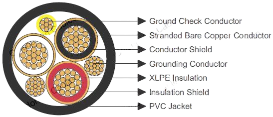
The insulation system represents a critical component of the cable's performance characteristics. A conducting layer conductor shield is applied directly over the copper conductor, providing a smooth, uniform interface between the conductor and the insulation layer. This shield eliminates air gaps and voltage stress concentrations that could lead to premature insulation failure.
Cross-linked polyethylene (XLPE) insulation offers superior electrical and thermal properties compared to traditional insulation materials. XLPE provides excellent dielectric strength, allowing the cable to maintain reliable performance at the 15kV operating voltage. The cross-linking process creates molecular bonds that enhance thermal stability, enabling continuous operation at conductor temperatures up to 90°C. This temperature rating allows higher current capacity compared to cables with lower temperature-rated insulation materials.
Over the XLPE insulation, an insulation shield consisting of a conducting layer and copper tape provides critical protective functions. The conducting layer creates a uniform electric field within the insulation, preventing surface tracking and corona discharge. The copper tape component serves multiple purposes: it provides a low-resistance path for charging currents, facilitates ground fault detection, and offers mechanical protection for the insulation layer.
Ground Check and Grounding Conductors
A distinguishing feature of the MP-GC cable is the inclusion of a ground check conductor with yellow polypropylene insulation. This conductor enables continuous monitoring of the grounding system integrity, a critical safety feature in mining environments where ground fault protection is essential for personnel safety. The distinctive yellow insulation allows easy identification during installation and maintenance procedures.
The tinned copper grounding conductor provides the primary ground fault return path. Tinning enhances corrosion resistance in the potentially harsh chemical environments encountered in mining operations, ensuring long-term grounding effectiveness. The grounding conductor size is proportioned to carry anticipated ground fault currents without excessive temperature rise.
Protective Jacket
The outer polyvinyl chloride (PVC) jacket in black provides comprehensive protection against mechanical damage, moisture infiltration, and chemical exposure. PVC offers excellent abrasion resistance, essential for cables that may be dragged across rock surfaces during installation or encounter moving equipment during operation. The black color provides UV resistance for open air installations while offering thermal advantages by radiating heat more effectively than lighter colors.
The jacket thickness is specified to provide adequate mechanical protection without creating excessive stiffness that would complicate installation. This balance between protection and flexibility represents a critical design consideration for mine power feeder cable applications.


Performance Characteristics and Operating Parameters
Temperature Ratings
The maximum conductor operating temperature of 90°C enables the cable to carry substantial current loads while maintaining adequate thermal margin for insulation longevity. This temperature rating is based on XLPE insulation characteristics and represents continuous operating conditions. The cable can withstand higher temperatures during overload conditions for limited durations, as specified by applicable standards.
Ampacity calculations assume a 40°C ambient air temperature, which represents typical conditions in many mining environments. However, in deep underground operations where rock temperatures may exceed 40°C, derating factors should be applied to ensure the conductor temperature does not exceed the 90°C maximum rating. Conversely, in cooler climates or ventilated areas, the cable may be capable of carrying currents exceeding published ratings.
Mechanical Properties
The minimum bending radius specification of 12 times the cable outer diameter protects the insulation system and conductors from damage during installation. Excessive bending creates stress concentrations in the insulation that can lead to cracking, void formation, or compression damage. The copper tape shield is particularly vulnerable to damage from tight bends, potentially creating breaks that compromise shielding effectiveness.
During installation, maintaining the minimum bending radius requires careful planning of cable routing, adequate clearances around corners, and appropriate pulling tensions. Training installation crews on these requirements prevents inadvertent cable damage that might not manifest as immediate failure but could reduce service life.
Ampacity Ratings and Conductor Selection
Available Conductor Sizes
The MP-GC three-conductor mine power feeder cable is available in conductor sizes from 2 AWG through 500 kcmil, providing options for applications ranging from small auxiliary circuits to main distribution feeders carrying hundreds of amperes. This size range accommodates the diverse power requirements encountered in mining operations, from lighting circuits and control systems to large motor loads and processing equipment.
Ampacity Considerations
Current-carrying capacity depends on multiple factors including conductor size, ambient temperature, installation method, and grouping with other cables. Published ampacity ratings typically assume single cables in free air at 40°C ambient temperature with 90°C conductor temperature. These ratings provide a conservative basis for system design, ensuring adequate thermal margin under normal operating conditions.
For direct burial installations, soil thermal resistivity significantly impacts ampacity. Dry soils with high thermal resistivity reduce heat dissipation, requiring derating compared to free air installations. Conversely, moist soils with good thermal conductivity may allow higher currents. Thermal analysis should consider worst-case soil conditions to prevent conductor overheating.
When multiple cables are installed in the same duct bank or cable tray, mutual heating effects reduce individual cable ampacity. Derating factors account for this thermal interaction, ensuring that the combined heat generation does not exceed the heat dissipation capacity of the installation environment.
Conductor Selection Guide
Selecting the appropriate conductor size requires analysis of the connected load, voltage drop limitations, fault current withstand capability, and economic considerations. For long feeder runs, voltage drop may become the limiting factor rather than ampacity, necessitating larger conductors than current capacity alone would require.
Short circuit calculations must verify that the conductor can withstand available fault currents for the time required for protective devices to clear the fault. The copper conductor's thermal mass and the insulation's short-time temperature capability determine the maximum permissible fault current duration.
Economic analysis should consider not only initial cable cost but also installation expenses and lifetime energy losses due to conductor resistance. Larger conductors have higher initial costs but lower resistance losses, potentially providing better lifecycle economics for heavily loaded feeders.


Cable Dimensions and Physical Properties
Dimensional Specifications
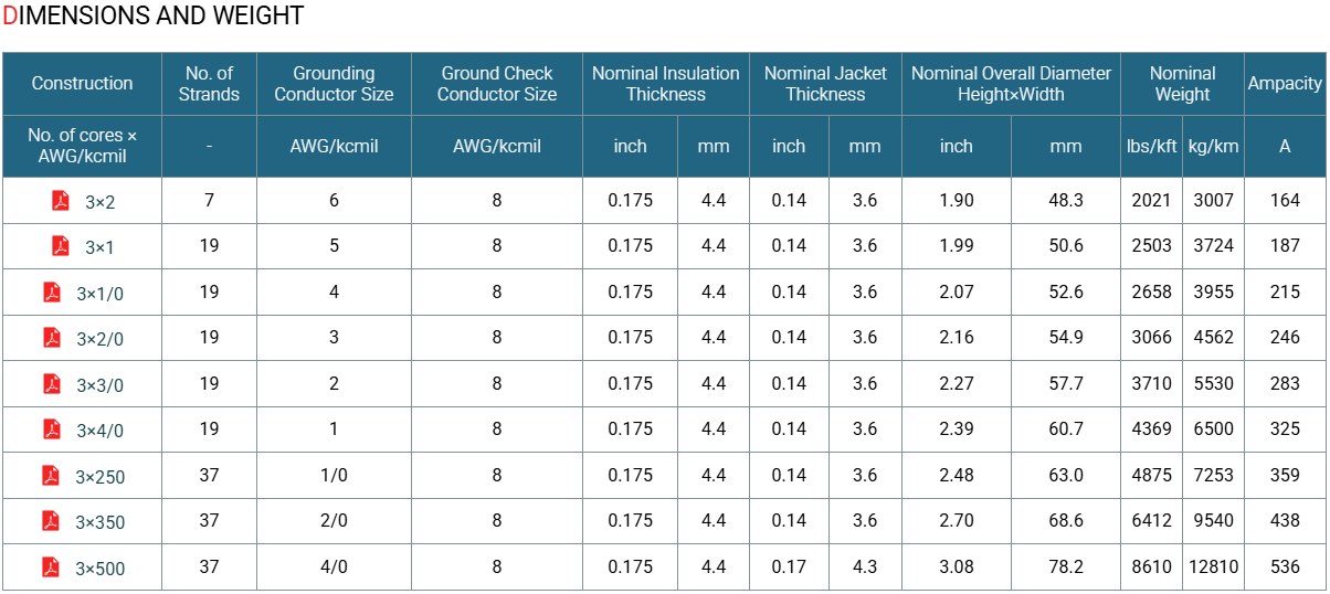
The overall cable diameter varies with conductor size, ranging from relatively compact dimensions for 2 AWG conductors to substantial diameters for 500 kcmil sizes. These dimensions impact conduit fill calculations, duct sizing, and trenching requirements. Engineers must account for cable diameter when designing installation pathways, ensuring adequate clearances for pulling operations and thermal expansion.
Insulation thickness remains consistent across conductor sizes, reflecting the voltage stress requirements at 15kV rather than mechanical considerations. This consistent insulation thickness ensures uniform electrical performance regardless of conductor size selection.
Jacket thickness provides mechanical protection proportional to the overall cable size. Larger cables with heavier conductors receive thicker jackets to withstand higher handling forces during installation and operation.
Weight Considerations
Cable weight, measured in pounds per thousand feet (lbs/kft) or kilograms per kilometer (kg/km), significantly impacts installation logistics. Heavier cables require more robust pulling equipment, additional support structures, and potentially larger installation crews. Weight specifications enable contractors to plan appropriate equipment and personnel for installation projects.
For direct burial installations, weight affects trenching depth requirements and backfill specifications. Heavier cables may require engineered backfill to prevent damage from soil loading, particularly in areas subject to vehicular traffic.
Transportation planning must consider cable weight limits for shipping containers and vehicles. Large projects may require multiple shipments or specialized transportation arrangements to deliver cable quantities economically and safely.


Conductor Options and Customization
Standard Configuration
The standard PVC jacket configuration provides excellent performance for the majority of mining applications, offering robust protection against mechanical damage, moisture, and moderate chemical exposure. This standard specification represents the optimal balance of performance, durability, and cost-effectiveness for general mine distribution systems.
Alternative Jacket Materials
For specialized applications, alternative jacket materials address specific environmental challenges. CSP (polycarbonate) jackets offer enhanced mechanical toughness and improved low-temperature flexibility, suitable for arctic mining operations or applications involving severe mechanical abuse. The superior impact resistance of polycarbonate makes it an excellent choice for areas where cable damage from rock falls or equipment impacts is a concern.
PCP jacket alternatives provide intermediate performance characteristics between standard PVC and premium materials, offering cost-effective solutions for applications requiring enhanced performance without the expense of top-tier jacket materials.
NBR (nitrile butadiene rubber) jackets excel in oil-resistant applications, protecting the cable in environments contaminated by hydraulic fluids, lubricants, or petroleum products. Mining operations using extensive hydraulic equipment or operating in oil-bearing geological formations benefit from NBR jacket resistance to hydrocarbon degradation.
TPU (thermoplastic polyurethane) jackets offer exceptional abrasion resistance and flexibility, ideal for applications involving frequent cable movement or exposure to sharp rock surfaces. The flexibility of TPU facilitates installation in confined spaces while maintaining excellent mechanical protection.
Custom Specifications
Many manufacturers can accommodate custom specifications upon request, including variations in conductor size, insulation thickness, jacket color, or marking requirements. Custom specifications enable mine operators to optimize cable performance for unique operational requirements or to integrate cables with existing color-coding systems for easier identification and maintenance.


Common Cable Issues and Solutions
Problem: Excessive Voltage Drop
Question: What causes excessive voltage drop in mine power distribution systems, and how can it be addressed?
Answer: Excessive voltage drop typically results from undersized conductors relative to load current and circuit length. The voltage drop formula (V = I × R × L) shows that drop increases with current, conductor resistance, and distance. Solutions include:
Upgrading to larger conductor sizes with lower resistance
Reducing circuit length by relocating distribution points
Operating at higher distribution voltages to reduce current for the same power level
Balancing loads across three phases to minimize neutral current
For existing installations, voltage drop can be mitigated by reducing load currents during peak demand periods or installing voltage regulators at critical loads.
Problem: Cable Overheating
Question: Why might mine power feeder cables overheat despite being rated for the connected load?
Answer: Cable overheating despite adequate ampacity ratings often stems from installation conditions that impair heat dissipation:
Multiple cables grouped together create mutual heating effects
Poor soil thermal conductivity in direct burial installations traps heat
Inadequate ventilation in duct systems prevents convective cooling
Ambient temperatures exceeding design assumptions (40°C standard)
Harmonic currents from variable frequency drives increase effective heating
Solutions include applying appropriate derating factors during design, improving installation thermal environments, installing cooling systems for confined spaces, and using harmonic filters to reduce non-sinusoidal current components.
Problem: Ground Fault Detection Issues
Question: How can mining operations ensure reliable ground fault detection with the MP-GC cable system?
Answer: The ground check conductor in the MP-GC cable enables continuous ground integrity monitoring. Proper implementation requires:
Connecting the ground check conductor to ground fault monitoring relays
Regular testing of ground continuity and resistance
Maintaining proper connections at cable terminations
Ensuring the copper tape shield remains intact throughout the cable length
Implementing ground fault protection schemes appropriate for 15kV systems
Ground faults in mining environments can result from insulation degradation, mechanical damage, or moisture infiltration. The redundant grounding system provided by the tinned copper grounding conductor and copper tape shield enhances safety by providing multiple fault current paths.
Problem: Cable Jacket Damage
Question: What causes jacket damage in mining cable installations, and how can it be prevented?
Answer: Jacket damage commonly occurs from:
Excessive pulling tension during installation
Sharp bend radius violations during installation or operation
Abrasion against rock surfaces or equipment
Chemical exposure exceeding PVC resistance capabilities
UV degradation in long-term open air installations
Mechanical impacts from equipment or rock falls
Prevention strategies include:
Using appropriate pulling lubricants and tension monitoring during installation
Installing cable protection such as cable trays, raceways, or burial depth adequate for soil loading
Selecting alternative jacket materials (NBR, TPU, CSP) for harsh environments
Implementing regular inspection programs to identify damage before insulation exposure
Providing physical barriers or guards in high-traffic areas


Installation Best Practices
Underground Installation Methods
Underground mine installations present unique challenges including confined spaces, moisture exposure, and dynamic ground conditions. Duct installation provides excellent cable protection while facilitating future cable replacement or additions. Ducts should be sized to allow easy cable pulling with adequate space for thermal expansion and future growth. The minimum bending radius must be maintained at all duct bends, requiring properly sized radius elbows or manufactured bends.
When installing in existing conduit systems, cable pulling calculations should account for friction, bend locations, and maximum sidewall pressure to prevent insulation damage. Pulling lubricants formulated for electrical cables reduce friction without degrading insulation or jacket materials.
Direct Burial Techniques
Direct burial installations require careful attention to trench preparation, cable laying methods, and backfill procedures. Trench bottoms should be smooth and free of rocks that could damage the cable jacket. A sand bedding layer provides uniform support and prevents point loading on the cable.
Cable should be laid with sufficient slack to accommodate soil settlement and thermal expansion without creating tensile stress. In areas subject to ground movement, additional slack allowances prevent cable stretching or insulation stress.
Backfill materials should be free of rocks, debris, or materials that could damage the cable. Engineered backfill provides consistent thermal conductivity for ampacity calculations and mechanical protection for the cable. Warning tape installed above the cable alerts future excavators to the cable presence, preventing inadvertent damage.
Safety Considerations
All installation work must be performed with appropriate safety precautions, including:
De-energizing and grounding connected circuits
Testing for absence of voltage before beginning work
Using personal protective equipment appropriate for electrical work
Following confined space entry procedures for underground installations
Implementing fall protection for elevated installations
Providing adequate lighting and ventilation in underground areas


Maintenance and Safety Monitoring
Inspection Procedures
Regular inspection programs should include visual examination of accessible cable sections, checking for jacket damage, abrasion, discoloration, or deformation. Thermographic surveys can identify hot spots indicating loose connections, unbalanced loads, or insulation deterioration. Partial discharge testing detects insulation degradation before complete failure occurs.
The ground check conductor enables continuous monitoring of grounding system integrity. Resistance measurements between the grounding conductor and ground check conductor verify that the grounding system remains effective. Sudden resistance changes indicate potential problems requiring investigation.
Environmental Considerations
The PVC jacket provides excellent resistance to moisture, moderate chemical exposure, and typical mining environment conditions. However, long-term exposure to certain chemicals may degrade jacket materials, requiring periodic inspection and potential replacement in aggressive environments. Alternative jacket materials should be considered for installations where PVC resistance is inadequate.
Conclusion
The Type MP-GC three-conductor mine power feeder cable with PVC jacket and 15kV rating represents a sophisticated solution for mining electrical distribution systems. Its combination of XLPE insulation, robust conductor construction, comprehensive shielding, integrated ground monitoring, and versatile installation capabilities makes it ideal for the demanding requirements of modern mining operations.
By understanding the technical specifications, proper installation methods, maintenance requirements, and potential challenges associated with this mining cable, operators can design and maintain reliable electrical distribution systems that enhance safety, operational efficiency, and long-term cost-effectiveness. The cable's compliance with ICEA, NEMA, ASTM, and CSA standards provides assurance of quality and performance, while the availability of custom specifications enables optimization for specific operational requirements.
Whether installed underground in wet conditions, directly buried in surface operations, or routed through conduit systems, the MP-GC three-conductor cable delivers dependable power distribution that mining operations demand. Its engineering reflects decades of mining industry experience, incorporating features that address real-world challenges while maintaining the flexibility to adapt to evolving operational needs.
How to Reach Us
Get in Touch
SiteMap
Product Catalogue
Festoon Cable
Shore Power Cable




Scan to add us on WeChat