

Type PLTC Cable: Complete Guide to Power-Limited Tray Cable for Industrial Control Systems
Comprehensive guide to Type PLTC (Power-Limited Tray Cable) for industrial control circuits. Learn NEC requirements, installation methods, applications, and construction standards. Ideal for substations, petrochemical facilities, and instrumentation systems.
hongjing.Wang@Feichun
12/25/20259 min read
Introduction
In modern industrial facilities, the reliability of control and instrumentation circuits is paramount to operational safety and efficiency. Type PLTC cable—Power-Limited Tray Cable—has emerged as the preferred wiring solution for low-voltage control systems across diverse industrial applications. Defined under NEC Article 725, PLTC cable represents a specialized category of tray cable engineered specifically for signal transmission, process control, and instrumentation circuits where power limitations ensure enhanced safety margins.
Unlike standard power distribution cables, PLTC cable operates at a maximum voltage rating of 300V, classifying it as a low-energy circuit solution. This voltage limitation, combined with rigorous mechanical and flame-resistance testing requirements, makes PLTC cable ideal for sensitive applications where signal integrity and system reliability are critical. From utility substations to petrochemical facilities, PLTC cable provides the robust performance demanded by harsh industrial environments while maintaining compliance with stringent electrical codes.
This comprehensive guide examines the technical specifications, installation methods, and real-world applications of PLTC cable, providing engineers, facility managers, and electrical contractors with the knowledge needed to select and implement optimal industrial control cable solutions.


What is Type PLTC Cable? Technical Definition
Type PLTC cable is a power-limited tray cable specifically designed for control circuit applications requiring enhanced mechanical protection and flame resistance. The designation "PLTC" directly references its dual characteristics: power-limited operation and suitability for installation in cable trays—one of the most common industrial cable management systems.
According to NEC Article 725 compliance standards, PLTC cable must satisfy several critical requirements that distinguish it from general-purpose tray cable. First, the 300-volt rating ensures that circuits remain within low-energy parameters, reducing arc flash hazards and simplifying installation requirements in occupied spaces. Second, PLTC cable must pass crush and impact resistance tests that verify its ability to withstand the mechanical stresses encountered in industrial tray installations, including accidental impacts and the weight of overlying cables.
The classification under NEC Article 725 as a Class 2 or Class 3 circuit cable provides specific advantages in terms of installation flexibility and code compliance. Unlike higher-voltage power cables that require extensive separation and conduit protection, PLTC cable can be routed alongside other control and signal cables with minimal restrictions, streamlining installation in congested cable trays typical of industrial facilities.
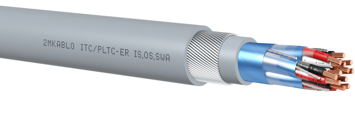
PLTC cable construction incorporates multiple protective layers—copper conductors, insulation, optional shielding, and a durable outer jacket—all engineered to deliver reliable signal transmission in environments subject to electromagnetic interference, temperature extremes, and chemical exposure.
Key Applications and Use Cases
Utility Substations
Utility substations represent the most prevalent application for PLTC cable. These facilities require extensive control and monitoring circuits for protective relays, SCADA systems, metering equipment, and remote terminal units. PLTC cable for utility substations provides the necessary flame resistance and mechanical durability while supporting the low-voltage requirements of digital communication protocols and instrumentation signals.
In substation environments, PLTC cable typically interconnects control panels, relay cabinets, and field devices distributed across the facility. The cable's approval for open tray installation simplifies routing through congested cable management systems while maintaining code compliance.
Industrial Process Control Systems
Manufacturing plants, chemical processing facilities, and industrial automation systems rely heavily on PLTC cable for instrumentation circuits. Process control applications demand reliable transmission of analog signals (4-20mA current loops) and digital communications between programmable logic controllers (PLCs), distributed control systems (DCS), sensors, and actuators.
Industrial instrumentation wiring using PLTC cable benefits from the availability of shielded configurations that protect against electromagnetic interference (EMI) and radio frequency interference (RFI) common in facilities with variable frequency drives, welding equipment, and other noise-generating sources.
Petrochemical and Refinery Environments
PLTC cable petrochemical applications require enhanced environmental resistance due to exposure to hydrocarbons, corrosive chemicals, and potentially explosive atmospheres. PLTC cable approved for Class I Division II hazardous locations provides compliant wiring solutions for control circuits in areas where flammable gases may be present under abnormal conditions.
The availability of CSPE (chlorosulfonated polyethylene) and CPE (chlorinated polyethylene) jacket materials offers superior oil and chemical resistance compared to standard PVC, extending cable service life in harsh refinery environments.
Mass Transit Control Systems
Mass transit control systems, including railway signal circuits, platform monitoring systems, and communication networks, utilize PLTC cable for reliable operation in both indoor and outdoor installations. The cable's flame resistance characteristics, specified by IEEE 1202 Vertical Tray Flame Test requirements, are particularly important in tunnels and enclosed stations where fire safety is paramount.
Additional Applications
Beyond these primary uses, PLTC cable serves effectively in:
Fire and burglar alarm systems requiring supervised circuit monitoring
Building automation and HVAC control systems in commercial facilities
Intercom and public address signaling systems
Point-of-sale systems and business machine power-limited circuits
Cable Construction and Materials
Conductor Configuration
PLTC cable construction begins with copper conductors available in both solid and stranded configurations. Stranded copper provides superior flexibility for installation through conduit and around obstacles, while solid conductors offer better performance in fixed installations where vibration is minimal.
Conductors are typically arranged in twisted pairs or triads, with the twisting pattern providing inherent noise rejection for signal transmission. This configuration proves especially valuable in industrial environments where long cable runs are susceptible to electromagnetic pickup from adjacent power cables and machinery.
Conductor sizing ranges from 22 AWG for low-current instrumentation circuits to 12 AWG for control applications requiring higher current capacity. Proper conductor size selection based on ampacity ratings and voltage drop calculations ensures reliable circuit operation.
Insulation Systems
The insulation layer provides electrical isolation and environmental protection for individual conductors. PVC insulation cable represents the most common choice, offering good dielectric strength, temperature ratings to 75°C or 90°C, and cost-effectiveness for general industrial applications.
EPR (ethylene propylene rubber) insulation serves as an alternative where enhanced flexibility, temperature performance, or chemical resistance is required. EPR-insulated conductors maintain superior flexibility at low temperatures compared to PVC, making them suitable for installations in unheated spaces or outdoor applications.
Shielding and Drain Wires
Shielded pairs triads provide critical EMI/RFI protection in electrically noisy environments. PLTC cable offers multiple shielding configurations:
Overall foil or braid shield covering all conductors
Individual pair or triad shields for maximum noise immunity
Combination shields with both overall and individual protection
Drain wire shielding accompanies foil shields to facilitate grounding connections. The drain wire, typically an uninsulated tinned copper conductor, runs in contact with the foil shield throughout the cable length, providing a low-impedance grounding path that enhances noise rejection.
Jacket Materials
The outer jacket serves as the cable's first line of defense against mechanical damage, chemical exposure, and environmental conditions. Material selection significantly impacts cable performance and longevity:
PVC jackets suit general industrial applications with moderate chemical exposure and temperatures within -20°C to 75°C operating ranges. Their flame-retardant properties meet standard fire safety requirements.
CPE (chlorinated polyethylene) jackets provide enhanced chemical resistance against acids, alkalis, and petroleum products while maintaining good abrasion resistance and flexibility.
CSPE (chlorosulfonated polyethylene) jackets, often marketed under the trade name Hypalon, offer superior oil resistance, UV stability for outdoor installations, and extended temperature ranges. CSPE jackets excel in petrochemical environments where hydrocarbon exposure is routine.
All jacket materials must exhibit flame-retardant properties verified through IEEE 1202 flame test protocols, which subject vertical cable samples to a 70,000 BTU/hr flame for specified durations.
Installation Methods and Code Requirements
Open Tray Installation
Open tray installation represents the primary method for routing PLTC cable in industrial facilities. NEC Article 725 requirements permit PLTC cable installation in cable trays without additional protection, provided the cable bears the appropriate markings and has passed required testing.
Cable tray systems must provide continuous rigid cable support with maximum spacing between supports determined by tray type and cable loading. Ladder trays, ventilated trough trays, and solid-bottom trays each offer different advantages regarding ventilation, cable support, and physical protection.
Direct Burial Installation
Direct burial PLTC cable installations require cables specifically rated and marked for underground use. The outer jacket must provide moisture resistance and protection against soil chemicals and physical damage from ground settling. Installation depth, bedding materials, and warning tape placement must comply with local electrical codes and utility coordination requirements.
Free-Air Installation with Rigid Cable Support
For applications where cable tray systems are impractical, PLTC cable may be installed in free air provided continuous rigid cable support is maintained. This installation method commonly appears in maintenance areas, equipment rooms, and spaces with minimal cable congestion. Support spacing must prevent excessive cable sag that could stress conductors or damage the outer jacket.
Concrete Encasement
PLTC cable maintains its performance characteristics when encased in concrete, making it suitable for installations in concrete floors, walls, or underground duct banks. This installation method provides maximum physical protection while maintaining the cable's electrical properties.
Standards, Testing, and Certifications
PLTC cable standards encompass multiple testing protocols that verify mechanical, electrical, and fire-resistance performance:
UL 1277 (Electrical Power and Control Tray Cable) establishes the primary requirements for tray cable construction, testing, and marking. This standard specifies crush resistance testing simulating cable tray loading conditions and impact testing replicating accidental strikes during installation or maintenance.
UL 83 (Thermoplastic Wire and Cable) and UL 44 (Thermoset-Insulated Wire and Cable) govern insulation system performance, including dielectric strength, insulation resistance, and temperature ratings.
IEEE 1202 flame test subjects vertical cable samples to a 70,000 BTU/hr propane flame, measuring flame spread, char length, and combustion products. PLTC cable certification requires meeting specific performance criteria that limit fire propagation in vertical cable runs.
CSA 22.3 cold bend and impact testing verifies cable performance under low-temperature conditions, ensuring the jacket and insulation maintain flexibility and mechanical integrity in cold climates or unheated spaces.
These PLTC cable certification requirements, administered by independent testing laboratories, provide specifiers with confidence that installed cables will perform reliably throughout their service life.
Common Problems and Troubleshooting Solutions
Problem 1: Signal Degradation in Long Cable Runs
Issue: Instrumentation signals become unstable or unreliable over distances exceeding 500 feet, particularly in 4-20mA analog loops.
Solution: Implement proper cable selection criteria including:
Use shielded cable with drain wire connections properly grounded at one end only to prevent ground loops
Select appropriate conductor size based on voltage drop calculations—typically 18 AWG minimum for runs exceeding 300 feet
Consider signal repeaters or isolators for distances approaching maximum loop resistance specifications
Verify shield integrity through continuity testing before energizing circuits
Problem 2: Jacket Cracking in Outdoor Installations
Issue: PVC jackets develop cracks after several years of UV exposure in outdoor cable tray installations, particularly in direct sunlight.
Solution: Specify CSPE jacket material for outdoor applications requiring UV resistance. For existing PVC-jacketed installations, implement protective measures:
Install cable tray covers to shield cables from direct sunlight
Route cables through covered walkways or building overhangs where possible
Schedule regular inspection procedures to identify degradation before moisture ingress damages conductors
Consider cable replacement using appropriate jacket material before widespread failure occurs
Problem 3: Electromagnetic Interference Affecting Control Signals
Issue: Digital communication circuits experience intermittent errors or analog signals show excessive noise when PLTC cable runs parallel to variable frequency drive (VFD) power cables.
Solution: Apply these installation best practices:
Maintain minimum separation of 12 inches between PLTC cable and VFD power cables in tray installations
Use individually shielded pairs for critical circuits rather than overall shield only
Route PLTC cable in separate trays or on opposite sides of ladder trays from power cables
Install line filters on VFDs to reduce conducted and radiated emissions
Ground shields properly using dedicated grounding conductors returned to a common ground point
Problem 4: Moisture Ingress in Underground Installations
Issue: Conductors show signs of corrosion or insulation resistance testing reveals degradation after several years in direct burial applications.
Solution: Ensure proper installation techniques for direct burial PLTC cable:
Verify cable is specifically rated for direct burial with moisture-resistant jacket
Install cables in sand bedding to promote drainage and prevent sharp rock contact
Maintain adequate burial depth (typically 24 inches minimum) with warning tape placed 12 inches above cable
Use waterproof splice kits and junction boxes for underground connections
Consider routing through concrete-encased conduits in areas prone to groundwater accumulation
PLTC Cable Selection Guide
Selecting appropriate PLTC cable for specific applications requires evaluating multiple technical and environmental factors:
Voltage Drop Considerations: Calculate maximum allowable voltage drop based on circuit requirements, typically 3-5% for control circuits. Use wire gauge selection charts accounting for cable length, current draw, and conductor material resistivity.
Environmental Assessment: Match jacket material to anticipated chemical exposure, temperature extremes, and UV exposure levels. Document environmental conditions to support material selection decisions.
Shielding Requirements: Specify shielded configurations for instrumentation circuits, analog signals, and digital communications susceptible to electromagnetic interference. Unshielded cable suffices for discrete digital inputs/outputs and alarm circuits in electrically quiet environments.
Pair Count Determination: Consolidate multiple circuits in multi-pair cables where possible to reduce installation labor and cable tray congestion. Balance consolidation against troubleshooting complexity and the risk of multiple circuit failures from single cable damage.
Conclusion
Type PLTC cable stands as the industry standard for industrial control cable applications requiring reliable performance in demanding environments. Its combination of power-limited safety characteristics, mechanical durability, and flame resistance addresses the critical requirements of modern industrial facilities, from utility substations to petrochemical plants.
Understanding PLTC cable specifications, proper installation methods, and application-specific requirements enables engineers and facility managers to implement robust control system infrastructure that delivers long-term reliability. Whether designing new facilities or upgrading existing installations, selecting appropriate PLTC cable configurations matched to environmental conditions and electrical requirements ensures optimal system performance while maintaining full NEC Article 725 requirements compliance.
As industrial automation continues advancing toward more sophisticated control architectures and higher communication speeds, PLTC cable technology evolves to meet emerging requirements while maintaining the fundamental characteristics that have established it as the preferred solution for power-limited circuits in industrial applications.
How to Reach Us
Get in Touch
SiteMap
Product Catalogue
Festoon Cable
Shore Power Cable




Scan to add us on WeChat