
What Are the AWG Sizes, Cross Sections, and Resistance Values in American Strand Construction?
Explore the fundamentals of American strand construction, including detailed AWG sizes, conductor cross sections, and resistance values. Learn how these electrical cable specifications affect cable performance in power, control, and industrial applications.
hongjing.Wang@Feichun
7/18/20259 min read
Introduction
In the complex world of electrical engineering and cable manufacturing, precision is paramount. The success of any electrical system—from industrial power distribution to sophisticated control networks—depends fundamentally on accurate cable specifications. At the heart of these specifications lies the American strand construction system, a standardized approach that has become the backbone of electrical conductor sizing across North America and beyond.
American strand construction encompasses a comprehensive framework that defines how conductors are sized, manufactured, and specified for various applications. This system, built around the American Wire Gauge (AWG) standard, provides engineers and designers with the critical data needed to select appropriate conductors for specific electrical requirements. Understanding AWG standards, cross-sectional areas, and resistance values is not merely academic—it directly impacts system performance, safety, and efficiency.
The importance of accurate cable specifications cannot be overstated. Incorrect conductor sizing can lead to excessive voltage drops, overheating, energy losses, and potential safety hazards. Conversely, proper understanding of American strand construction enables engineers to optimize electrical systems for maximum performance while maintaining cost-effectiveness and reliability.
What Is AWG and How Does It Define Conductor Size?
The American Wire Gauge (AWG) system represents one of the most widely used standardized methods for defining conductor sizes in electrical applications. This logarithmic scale provides a systematic approach to categorizing wire diameters, with each AWG number corresponding to specific dimensional and electrical characteristics.
The fundamental principle underlying AWG sizing is its inverse relationship with conductor diameter. As the AWG number increases, the actual wire diameter decreases proportionally. This counterintuitive relationship often confuses newcomers to the field, but it follows a logical mathematical progression. For example, 10 AWG wire has a diameter of 2.59 mm, while 20 AWG wire measures only 0.812 mm in diameter—demonstrating how higher AWG numbers indicate progressively thinner conductors.
This inverse relationship extends beyond simple diameter measurements to encompass cross-sectional area and current-carrying capacity. A 10 AWG conductor with its 5.26 mm² cross-section can handle significantly more current than a 20 AWG conductor with its 0.519 mm² cross-section. This correlation between AWG number, physical dimensions, and electrical capacity forms the foundation for proper conductor selection in electrical design.
For larger conductor sizes, the AWG system transitions to MCM (thousand circular mils) units. This transition occurs because expressing very large conductors in AWG terms becomes unwieldy—the largest standard AWG size is 4/0 (also written as 0000), beyond which MCM units provide a more practical measurement system. MCM conductor sizing follows a different numerical progression, with common sizes including 250 MCM, 500 MCM, 750 MCM, and 1000 MCM.
Understanding AWG cable size charts and AWG vs MCM conductor sizing becomes essential for engineers working with diverse electrical systems. The transition between these measurement systems represents a critical knowledge point for anyone involved in cable specification or electrical design.
Understanding Cross Section (mm²) and Its Role
The conductor cross-sectional area, measured in square millimeters (mm²), represents perhaps the most critical specification in cable design. This measurement directly determines the conductor's current-carrying capacity, resistance characteristics, and overall electrical performance. While AWG and MCM provide standardized sizing references, the actual cross-sectional area governs the fundamental electrical properties of the conductor.
Cross-sectional area influences current-carrying capacity through basic electrical principles. Larger cross-sectional areas provide more pathways for electron flow, reducing resistance and enabling higher current handling capabilities. This relationship explains why power transmission systems utilize conductors with hundreds of square millimeters of cross-sectional area, while control circuits might require only a few square millimeters.
The conversion between AWG/MCM and mm² requires precise calculations, as even small variations can significantly impact electrical performance. For instance, 4/0 AWG corresponds to 107.2 mm², while 2/0 AWG equals 67.4 mm². These exact values differ from commonly used approximations, and engineers must understand when to use precise figures versus rounded values in their calculations.
Commercial cable manufacturers sometimes use approximations for convenience, but engineering calculations demand exact values. The difference between using 107 mm² versus the precise 107.2 mm² might seem negligible, but in large-scale installations or critical applications, these small variations can accumulate to create significant performance differences.
Conductor cross section calculations also factor into cable size conversion processes. Engineers frequently need to convert between different measurement systems—from AWG to mm², from MCM to mm², and sometimes to other international standards. Understanding these conversions enables proper cable selection regardless of the specification format used by manufacturers or project requirements.


Conductor Resistance: Why It Matters
Conductor resistance, measured in ohms per kilometer (Ω/km), represents a fundamental electrical property that directly affects system performance, energy efficiency, and voltage regulation. This parameter quantifies the opposition that a conductor presents to current flow over a standardized distance, providing engineers with essential data for calculating voltage drops and power losses.
The relationship between conductor size and resistance follows predictable patterns. Larger conductors exhibit lower resistance values, while smaller conductors present higher resistance. This inverse relationship is clearly demonstrated in the technical data: 1000 MCM conductors show resistance values of 0.036 Ω/km, while 30 AWG conductors exhibit resistance values of 350.0 Ω/km—nearly 10,000 times higher.
These resistance values have profound implications for electrical system design. High resistance leads to voltage drops, where the voltage available at the load end of a circuit is lower than the voltage at the source. In power distribution systems, excessive voltage drops can cause motors to operate inefficiently, lights to dim, and sensitive electronic equipment to malfunction. Energy losses due to resistance also translate directly into increased operating costs and reduced system efficiency.
Real-world applications demonstrate the importance of understanding cable resistance per km. Consider a 10 AWG conductor with 3.64 Ω/km resistance carrying 20 amperes over a 100-meter distance. The voltage drop would be approximately 7.28 volts (20A × 3.64 Ω/km × 0.1 km), which could be significant in a 120-volt circuit. Conversely, using 4/0 AWG conductor with 0.18 Ω/km resistance would reduce the voltage drop to only 0.36 volts under the same conditions.
Low-resistance cables become essential in applications where voltage regulation is critical or where long conductor runs are necessary. Power transmission systems, industrial motor circuits, and sensitive instrumentation applications all benefit from conductors with minimal resistance characteristics.
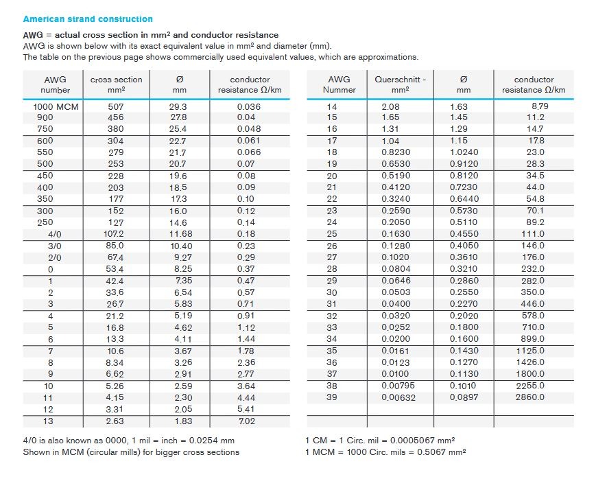
AWG & MCM Reference Table
Understanding the relationship between AWG sizes, cross-sectional areas, and resistance values requires access to accurate reference data. The following comprehensive table provides essential specifications for common American strand construction sizes:
Large Conductor Sizes (MCM)
1000 MCM: 507 mm² cross-section, 29.3 mm diameter, 0.036 Ω/km resistance
900 MCM: 456 mm² cross-section, 27.8 mm diameter, 0.04 Ω/km resistance
750 MCM: 380 mm² cross-section, 25.4 mm diameter, 0.048 Ω/km resistance
600 MCM: 304 mm² cross-section, 22.7 mm diameter, 0.061 Ω/km resistance
Standard AWG Sizes
4/0 AWG: 107.2 mm² cross-section, 11.68 mm diameter, 0.18 Ω/km resistance
2/0 AWG: 67.4 mm² cross-section, 9.27 mm diameter, 0.29 Ω/km resistance
10 AWG: 5.26 mm² cross-section, 2.59 mm diameter, 3.64 Ω/km resistance
20 AWG: 0.519 mm² cross-section, 0.812 mm diameter, 34.5 Ω/km resistance
30 AWG: 0.0503 mm² cross-section, 0.255 mm diameter, 350.0 Ω/km resistance
This data reveals clear patterns in conductor characteristics. As conductor size increases (lower AWG numbers or higher MCM values), cross-sectional area increases proportionally, while resistance decreases dramatically. These relationships provide the foundation for proper conductor selection in electrical design applications.
Common Applications of American Strand Construction
American strand construction finds applications across diverse industries and electrical systems, each with specific requirements for conductor sizing and performance characteristics. Understanding these applications helps engineers select appropriate conductors for their specific needs.
Power Transmission and Distribution Systems Large MCM conductors form the backbone of electrical power transmission networks. These systems require conductors capable of carrying thousands of amperes over long distances with minimal losses. The 1000 MCM and 750 MCM sizes commonly appear in utility transmission lines, where their low resistance characteristics (0.036 Ω/km and 0.048 Ω/km respectively) minimize energy losses during power transmission.
Industrial Machinery Wiring Manufacturing facilities rely heavily on American strand construction for motor feeds, control circuits, and power distribution. Industrial cable applications typically utilize 4/0 AWG through 12 AWG conductors, depending on the specific application. Motor feeder circuits might use 2/0 AWG or 4/0 AWG conductors, while control circuits often employ 14 AWG or 16 AWG conductors.
Automotive and Aerospace Cabling The automotive industry extensively uses American strand construction for vehicle electrical systems. Battery cables typically employ 4/0 AWG or 2/0 AWG conductors to handle high starter motor currents, while lighting and accessory circuits use smaller AWG sizes. Aerospace applications demand precise conductor specifications due to weight constraints and reliability requirements.
Instrumentation and Control Systems Control cable design often requires smaller AWG sizes for signal transmission and low-power applications. These systems typically use 18 AWG through 24 AWG conductors, where the higher resistance values are acceptable due to the low current requirements. However, signal integrity and electromagnetic interference considerations become more important than pure current-carrying capacity.

Engineering Tips: Choosing the Right AWG Size
Selecting the appropriate AWG size requires careful consideration of multiple factors that affect electrical performance, safety, and cost-effectiveness. Engineers must balance various requirements to achieve optimal system performance while maintaining economic viability.
Load Requirements and Current Capacity The primary consideration in AWG selection is the current-carrying capacity required by the load. However, this involves more than simply matching conductor ampacity to load current. Engineers must account for ambient temperature, conductor bundling, and installation methods, all of which affect the conductor's ability to dissipate heat safely.
Distance and Voltage Drop Calculations Long conductor runs require careful analysis of voltage drop effects. The relationship between conductor resistance, current, and distance determines the voltage drop: VD = I × R × L. Engineers must ensure that voltage drop remains within acceptable limits (typically 3-5% for most applications) while balancing conductor cost and performance.
Heat Dissipation and Thermal Management How to choose the right AWG cable involves understanding thermal characteristics. Smaller conductors have higher resistance, generating more heat per unit current. This heat must be dissipated safely to prevent insulation damage and maintain conductor integrity. Proper conductor sizing ensures that thermal limits are not exceeded under normal operating conditions.
Flexibility and Mechanical Requirements Some applications require flexible conductors that can withstand repeated bending or vibration. Larger conductors tend to be less flexible, which might necessitate using multiple smaller conductors in parallel rather than a single large conductor. This approach can provide the required current capacity while maintaining mechanical flexibility.
Commercial vs. Exact Values Cable sizing for electrical loads requires understanding when to use exact values versus commercial approximations. Critical applications demand precise calculations using exact cross-sectional areas and resistance values, while less critical applications might accommodate standard commercial approximations.
Q&A
What is the relationship between AWG and wire diameter? AWG numbers have an inverse relationship with wire diameter—higher AWG numbers indicate thinner wires. This relationship follows a logarithmic scale where each decrease of 3 AWG numbers doubles the cross-sectional area and decreases resistance by approximately half.
Why is resistance in cables measured in ohms per kilometer? Resistance per kilometer provides a standardized measurement that allows engineers to calculate voltage drops and power losses over any distance. This unit enables direct calculation of resistance for specific cable lengths and facilitates comparison between different conductor types and sizes.
How does cross-sectional area affect current-carrying capacity? Cross-sectional area directly determines current-carrying capacity through its relationship with conductor resistance and heat dissipation. Larger cross-sectional areas provide more pathways for current flow, reducing resistance and enabling better heat dissipation, which allows for higher current capacity.
What applications require low-resistance American strand cables? Power transmission systems, large motor feeders, welding applications, and long-distance electrical distribution systems all require low-resistance cables. These applications benefit from reduced voltage drops, improved efficiency, and lower operating costs achieved through minimal conductor resistance.
Conclusion
American strand construction represents a fundamental aspect of electrical engineering that directly impacts system performance, safety, and efficiency. The comprehensive understanding of AWG sizing, cross-sectional areas, and resistance values enables engineers to make informed decisions that optimize electrical systems for their intended applications.
The inverse relationship between AWG numbers and conductor size, the transition to MCM units for large conductors, and the critical importance of accurate resistance values all contribute to the complexity of proper conductor selection. However, mastering these concepts provides engineers with the tools necessary to design reliable, efficient electrical systems.
The applications of American strand construction span from massive power transmission systems using 1000 MCM conductors to delicate instrumentation circuits employing 24 AWG conductors. Each application presents unique challenges and requirements, but the underlying principles remain consistent.
Following electrical cable standards and utilizing comprehensive AWG sizing guides ensures that conductor selection meets both technical requirements and safety standards. The precision demanded in cable design best practices reflects the critical nature of electrical systems in modern society.
As technology continues to advance and electrical systems become more sophisticated, the importance of accurate conductor specifications only increases. Engineers who understand American strand construction principles are better equipped to design systems that meet today's performance requirements while providing the reliability and efficiency that future applications will demand.
How to Reach Us
Get in Touch
SiteMap
Product Catalogue
Festoon Cable
Shore Power Cable


Scan to add us on WeChat