
What Caused This Port Crane Cable Breakdown?
Discover the most common causes of port crane cable failures, including abrasion, torsion, thermal overload, improper fleet angle, bending radius violations and poor installation practices. Learn how to prevent costly downtime in STS, RTG and automated crane systems.
hongjing.Wang@Feichun
6/8/202637 min read
Introduction
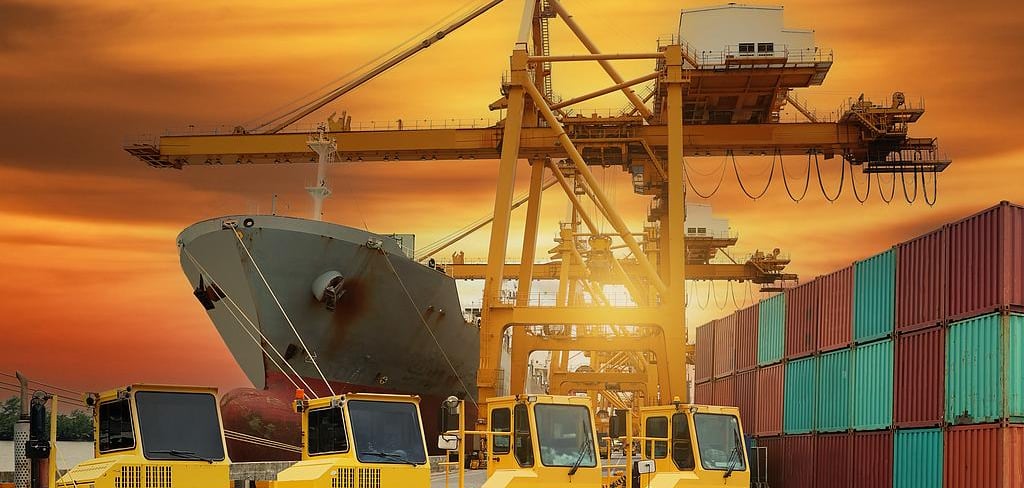
It's a Tuesday morning at a busy container terminal. A vessel is alongside, the schedule is tight, and the ship-to-shore cranes are working hard to clear the boxes. Then one of them stops. Not a controlled pause — a full shutdown. The operator reports a fault, the crane won't move, and within minutes the carefully choreographed flow of containers across the quay begins to back up. Trucks queue. Boxes accumulate. The vessel's departure time, fixed days ago, suddenly looks shaky.
The maintenance crew arrives and works through the diagnostics, and the culprit emerges: the crane's reeling cable has failed. Somewhere along its length, or down inside the reel, the cable that feeds power to the moving crane has given up. The crane is dead until it's repaired or replaced, and every hour it stays down costs money and disrupts the whole terminal.
Here's the thing that experienced maintenance people understand and newcomers often don't: this failure didn't happen on Tuesday morning. The cable didn't suddenly decide to break. What failed that morning was the final, visible symptom of damage that had been developing for months, sometimes years. Cable failures rarely happen without warning. They're the end point of a slow, progressive process — mechanical wear grinding away a little more each cycle, thermal stress hardening the insulation over countless hot afternoons, a bending radius violation fatiguing the conductors one flex at a time, or environmental attack eating into the jacket season after season. By the time the cable actually breaks, the real cause is usually well in the past.
That's what makes root cause analysis so important, and it's the purpose of this article. When a crane cable fails, the visible damage tells you what broke, but rarely why it broke. Replace the cable without understanding the cause, and you've simply reset the clock on the same failure — the new cable will travel the same path to the same end. Understand the root cause, and you can fix the underlying problem, extend the life of every cable that follows, and stop the breakdown from recurring. This article walks through the most common root causes of port crane cable failures, explains how each one works and how to recognise it, and sets out practical strategies to prevent costly downtime in ship-to-shore, rubber-tyred gantry and automated crane systems.
Why Crane Cable Failures Are So Costly
Before getting into causes, it's worth being clear about why this matters so much, because the cost of a crane cable failure extends far beyond the price of the cable itself. The cable might be a few thousand dollars, or tens of thousands for a long medium-voltage run. The consequences of its failure are an order of magnitude larger.
Equipment downtime is the first and most obvious cost. A crane that's down isn't earning its keep, and on a terminal where cranes are the productive heart of the operation, idle crane hours translate directly into lost throughput. Then there are vessel delays. Container ships run to tight schedules, and a ship that can't be worked fast enough because a crane is out of action may miss its departure window, incurring penalties and knock-on disruption that ripples down the vessel's entire route. The terminal may face demurrage claims, and its reputation for reliable, fast turnaround — a key competitive factor — takes a hit.
Emergency maintenance costs pile on top. A planned cable replacement during scheduled downtime is a manageable, budgeted job. An emergency replacement, with the crane already stopped and the pressure on, means rush-ordering cable if none is in stock, mobilising crews at short notice, possibly paying premium rates and working around the clock to get the crane back. The same job costs far more when it's an emergency than when it's planned. Beyond the immediate failure, a terminal running cables towards failure rather than replacing them proactively also suffers reduced crane productivity in the lead-up, as intermittent faults and derating creep in before the final breakdown.
And then there's safety. A failing power cable on a large crane isn't just an operational problem; it's a potential hazard. Damaged insulation can create electrical risks, and a cable that fails catastrophically under tension can be dangerous to people nearby. The safety dimension alone justifies treating cable reliability as a serious matter rather than an afterthought.
Put all of this together and the picture is clear: modern container terminals depend heavily on reliable reeling cable systems. The cable is a small, unglamorous component, but its failure stops the whole show. That's precisely why understanding and preventing cable failures repays the effort many times over.
It's worth putting the economics in perspective with a simple comparison. Consider the two paths a cable nearing the end of its life can take. On the first path, the operator runs a planned inspection program, notices the cable is deteriorating, schedules a replacement during a window when the crane isn't needed, has the replacement cable on hand, and swaps it out in a controlled, unhurried job. The cost is the cable, a few hours of planned labour, and zero lost productivity because the work happens when the crane would have been idle anyway. On the second path, the same cable is left to run until it fails mid-shift. Now the crane stops unexpectedly, the terminal scrambles, a replacement cable may have to be sourced urgently at premium cost, crews are mobilised at short notice and possibly at overtime rates, the work happens under pressure with a vessel waiting, and every hour of the unplanned outage carries lost throughput and possible vessel-delay penalties. The cable itself costs the same on both paths. Everything around it — the timing, the labour, the lost productivity, the knock-on disruption — can differ by an order of magnitude. This contrast is the entire financial argument for understanding failure causes and acting on them proactively: the cable is cheap, but the manner of its failure is what costs the money, and that manner is largely within the operator's control.
There's also a compounding effect worth noting. A terminal that lets cables run to failure doesn't just suffer the occasional dramatic breakdown; it lives with chronic unreliability. Intermittent faults in the lead-up to failure cause stoppages and reduce crane availability. Emergency jobs disrupt planned maintenance schedules and pull crews off other work. And the unpredictability makes it hard to plan vessel operations with confidence. Conversely, a terminal that understands and manages its cable failure modes runs more predictably across the board, which is valuable in ways that go beyond the direct cost of any single failure.
Understanding the Operating Environment of Port Crane Cables
To understand why these cables fail, you first have to appreciate the punishing conditions they operate in. A port crane cable lives one of the hardest lives of any cable anywhere. It's not a cable bolted to a wall in a clean, climate-controlled building; it's a cable that moves, flexes, carries heavy loads and battles the elements continuously. Four aspects of that environment stand out.
Continuous Flexing and Reeling
A reeling cable is bent and straightened on every single travel cycle of the crane. As the crane moves, the cable winds onto the reel, bending around the drum, then pays off again, straightening out. Multiply that by the number of times a crane travels in a shift, then by the shifts in a day, the days in a year, and the years of intended service, and the numbers become staggering. Over its service life, a crane cable may experience millions of bending cycles. Each individual flex is gentle enough, but it's the relentless repetition that does the damage. Like a paperclip bent back and forth until it snaps, a cable subjected to millions of flexing cycles will eventually fatigue — unless it's specifically engineered for the duty and operated within its limits. Continuous flexing is the defining stress of reeling cable life, and many failure modes trace back to it.
What makes flexing fatigue particularly demanding is that it attacks the cable at the microscopic level, inside the conductors, where it can't be seen. Each conductor in a flexible cable is made up of many fine strands, deliberately stranded finely so the cable can bend without the individual strands being over-stressed. Every flex works those strands slightly, and over millions of cycles, microscopic damage accumulates in the metal until strands begin to break. As strands break, the remaining strands carry more current and more mechanical load, so they fatigue faster, and the failure accelerates towards the end. This is why a cable can seem fine for most of its life and then fail relatively quickly once the fatigue process reaches its later stages. It also explains why the quality of the conductor construction matters so much: a cable with finely stranded, well-designed conductors and appropriate reinforcement survives far more flexing cycles than one built to a lower standard, even though both might look similar from the outside.
High Travel Speeds
Cranes are not slow. Modern crane travel speeds can exceed 120 metres per minute, and in some highly automated terminals, travel speeds approach 300 metres per minute. At those speeds, the reel has to wind and unwind cable rapidly, and the cable has to flex and move fast. Higher speed means more cycles in less time, accelerating fatigue, and it also means greater dynamic forces every time the crane starts and stops. The trend towards faster, more automated cranes raises the bar on what the cable and the reeling system have to withstand, and a cable that coped fine at lower speeds may struggle when the operation speeds up.
Dynamic Tensile Loads
A crane cable isn't subjected to a steady, constant tension. It experiences dynamic loads — forces that change as the crane accelerates, decelerates and responds to sudden operational changes. Every time the crane lurches into motion or brakes to a halt, the cable feels it. These dynamic tensile forces can be significant, and they're particularly demanding because they're variable and sometimes sudden. A cable might handle a steady pull comfortably yet suffer under repeated shock loading from harsh acceleration and braking. The reeling system's tension control is meant to manage these forces, but where it falls short, the cable pays the price.
The cable's own weight adds to this, especially on long-travel systems and in any application where the cable hangs or is supported only at intervals. When a crane is at the far end of its travel and a long length of cable is paid out, that cable has to support its own weight, and the tension at the reel end can be considerable. In vertical or near-vertical reeling, such as some spreader applications, the cable effectively hangs from its connection, and the weight tension is borne continuously. A cable not designed with adequate tensile strength — ideally with a dedicated strength member to carry the load rather than letting the conductors bear it — will see its conductors stretched and fatigued by the constant pull. This is one reason higher-end reeling cables incorporate aramid or other high-tensile reinforcement: it carries the tensile load that would otherwise fall on the conductors, protecting them from a stress they're not meant to bear. Where dynamic and weight-related tension is high, matching the cable's tensile capability to the duty is essential, and getting it wrong leads to a slow stretching and fatiguing that ends in conductor failure.
Harsh Marine Conditions
On top of all the mechanical stress, the port environment itself is brutal. The cable is exposed to salt spray and salt-laden air, which corrode and degrade both the cable and its terminations. There's ultraviolet radiation from constant sun exposure, which breaks down jacket materials over time. There's humidity, which combined with temperature changes can drive moisture towards the cable's interior. There are high temperatures, especially in the Australian summer, which stress the insulation and accelerate ageing. And there's wind-blown dust and grit — coal dust, ore fines, general port grime — which works into the winding and acts as an abrasive. Each of these factors degrades the cable, and together they accelerate the ageing process considerably. A cable that might last comfortably in a sheltered factory can age rapidly in the exposed, salty, hot, dusty environment of a working port.
When you combine continuous high-cycle flexing, high speeds, dynamic loads and a hostile environment, you have an operating regime that demands a purpose-built cable and careful system design. It's also an operating regime that, when anything is even slightly wrong, finds the weakness and exploits it relentlessly. That's the context in which all the failure modes below take place.
It's helpful to hold this context in mind throughout the rest of the article, because it explains a recurring theme: port crane cables operate with very little margin for error. A cable in a benign application can tolerate a degree of imperfection — a slightly tight bend, a bit of contamination, a modestly elevated temperature — and still last its expected life, because none of those stresses is severe and they don't compound. A port crane cable enjoys no such forgiveness. It's already working near the edge of what's reasonable to ask of a cable, so any additional stress — a fleet angle that's a degree too steep, a drum a size too small, a jacket not quite up to the UV and salt, a current load a little too high on a hot day — pushes it over the edge and dramatically shortens its life. This is why the failure modes that follow are so consequential, and why the prevention measures are worth the discipline they require. In a demanding application with no margin to spare, the details that might be forgiven elsewhere become the difference between a cable that lasts and one that fails.
Case Study: A Port Crane Cable Breakdown Investigation
Let's ground the discussion in a realistic scenario, the kind that plays out at terminals around the world.
A ship-to-shore crane had been giving intermittent trouble for a couple of weeks. Nothing dramatic at first — an occasional fault that cleared itself, a momentary loss of signal, a brief unexplained stop that the operator put down to a glitch. The faults grew more frequent. Then, mid-shift, the crane shut down completely and wouldn't restart.
The maintenance team went to the reeling cable. Their initial inspection found several things. The cable's outer jacket was damaged in places, worn and scuffed. There was localised twisting along one section, the cable showing a slight corkscrew where it should have run straight. And when they investigated further, they found broken conductors inside — the actual electrical failure that had finally stopped the crane.
So what caused the failure? It's tempting to point at the broken conductors and call it solved. But the broken conductors are where the story ended, not where it began. The visible damage — the worn jacket, the twisting, the broken conductors — is the final symptom, the accumulation of an underlying problem that had been at work for a long time. The real investigation asks: why was the jacket worn in that spot? Why was the cable twisting? What drove the conductors to fatigue and break? The answers lie in the root causes that follow, and a proper analysis works backwards from the symptoms to find which of them was really responsible. In most real failures, it's a combination — one primary cause, often compounded by others. The discipline is to look past the obvious final damage and ask what set it in motion.
Why Failure Modes Rarely Act Alone
Before working through the individual causes, it helps to recognise that they seldom operate in isolation, and that this interconnection is often what makes a failure investigation tricky. The eight root causes covered in this article — abrasion, bending radius violation, fleet angle problems, torsion, thermal overload, crushing, environmental degradation and installation or maintenance failures — are not separate boxes. They feed into one another. A poor fleet angle causes uneven winding, which causes both crushing at the crossover points and abrasion as cable rubs against cable. Environmental degradation weakens a jacket, which then abrades more easily, and once the jacket is breached, salt and moisture reach the conductors. An installation twist creates torsion, which distorts the cable's geometry and concentrates flexing stress in the wrong places. Thermal overload hardens insulation, which then cracks under continued flexing.
This interconnection has two practical implications. First, when investigating a failure, finding one cause doesn't mean the job is done — it's worth asking what other factors contributed and whether the primary cause itself had an underlying driver. A crushed inner layer might be the visible damage, but the real culprit could be the poor fleet angle that caused the uneven winding that concentrated the crushing. Second, prevention is cumulative: fixing the reel geometry doesn't just prevent crushing, it also reduces abrasion and twisting at the drum. Addressing one root cause often improves several failure modes at once, which is part of why getting the fundamentals right — the reel, the installation, the environmental protection — delivers such disproportionate benefit. With that interconnection in mind, the individual causes are easier to understand and to act on.
Failure Cause #1 – Excessive Abrasion and Mechanical Wear
Abrasion is one of the most common cable failure mechanisms in port cranes, and one of the most straightforward to understand: the cable rubs against something, over and over, until its protective layers wear away.
Typical Symptoms
Abrasion damage announces itself visually. You'll see a worn outer sheath, where the jacket has been ground down and thinned, often along a particular section that contacts whatever is causing the wear. In more advanced cases, the wear breaks through the jacket entirely and exposes the reinforcement or screening layers beneath — a clear sign the cable is well on its way to failure. Sometimes you'll find flattened cable sections, where pressure combined with rubbing has deformed the cable's normally round profile. The pattern of wear is often a clue to the cause: a consistent worn patch in the same place points to the cable repeatedly contacting a fixed object or running through a poorly designed guide.
Root Causes
Abrasion doesn't happen by itself; something is rubbing the cable. Improper support systems are a frequent culprit — if the cable isn't guided and supported correctly along its path, it can drag against structures it shouldn't touch. Cable rubbing against fixed structures — the crane framework, the festoon track, edges and corners — wears it down wherever the contact occurs. Poor reel alignment can cause the cable to chafe against the reel flanges or guides as it winds. And contaminated cable pathways, where dust, grit and debris accumulate, turn every movement into a sanding action, the abrasive particles accelerating the wear dramatically. In a dusty port environment, this last factor is especially significant.
How It Progresses
The danger of abrasion is that it's progressive and, for a long time, invisible in its consequences. The jacket exists to protect what's inside — the reinforcement, the insulation, the conductors. As abrasion gradually removes the protective layers, the cable keeps working, apparently fine, right up until the protection is breached. Once the jacket is worn through, moisture, salt and contaminants can reach the inner layers and ultimately the conductors. From there, insulation degrades, corrosion sets in, and electrical failure follows. The cable that fails from abrasion often looked "a bit worn" for months before anyone acted, because the wear seemed cosmetic until suddenly it wasn't.
Preventive Measures
Preventing abrasion is largely about routing and vigilance. Proper cable routing ensures the cable runs a clean path without contacting structures it shouldn't, with adequate clearance and support throughout its travel. Improved guide systems — well-designed rollers, sheaves and guides that handle the cable smoothly — keep it moving without chafing. Keeping pathways clean reduces the abrasive grit that accelerates wear. And regular inspections catch abrasion early, while it's still confined to the jacket and before it reaches the point of failure. A worn patch spotted and addressed early is a minor maintenance note; the same patch ignored becomes a breakdown. The visible nature of abrasion is actually an advantage to the diligent — it gives clear warning, if someone is looking.
It's also worth treating any localised abrasion as a question rather than just a finding. A worn patch in one consistent spot is telling you that the cable contacts something at that point in its travel, and the fix is to find and address that contact, not merely to replace the cable. If you replace the cable but leave the cause in place — the misaligned guide, the protruding edge, the worn roller — the new cable will wear in exactly the same spot and fail the same way. This is the abrasion version of the broader principle running through this whole article: the visible damage is a symptom, and lasting prevention means tracing it to its source. A few minutes spent identifying what the cable is rubbing against, and correcting it, is worth far more than the cable replacement itself. In dusty bulk-handling environments, where wind-blown grit is unavoidable, the emphasis shifts towards keeping guides and pathways as clean as practical and choosing cables with the toughest abrasion-resistant jackets, since the abrasive environment itself can't be eliminated.
[Suggested images: close-up photographs showing jacket wear progressing to exposed conductors.]
Failure Cause #2 – Exceeding the Minimum Bending Radius
Every cable has a minimum bending radius — the tightest curve it can be bent to without damage. For reeling cables, which bend on every cycle, respecting this radius is absolutely critical, and violating it is a common and serious cause of failure.
What Happens Inside the Cable
When a cable is bent more tightly than its minimum radius, the damage occurs inside, out of sight, which is part of what makes this failure mode so insidious. The conductors, forced into too tight a curve repeatedly, suffer fatigue — the metal strands flex beyond their comfortable range and, over many cycles, begin to fracture. The insulation, compressed on the inside of the bend and stretched on the outside, cracks under the repeated strain. Any shielding or screening layers can be damaged and distorted. None of this is visible from outside until the cumulative internal damage finally manifests as an electrical fault or a visible deformation. A cable being over-bent looks perfectly normal right up until it fails.
The reason a tighter bend is so much more damaging than a gentle one comes down to how strain scales with bend radius. The tighter the curve, the more the outer part of the cable has to stretch and the inner part has to compress relative to the neutral axis running through the centre. Halve the bend radius and you roughly double the strain on the conductors and insulation at the extremes. Because fatigue damage accumulates faster as strain increases, the relationship between bend tightness and cable life is steep — a modest reduction in bend radius can translate into a large reduction in service life. This is precisely why manufacturers specify a minimum bending radius with such care, and why exceeding it even somewhat can shorten life dramatically rather than marginally. It also explains why the first layer on the drum, wound at the tightest radius of any layer, is the worst case and why the barrel diameter is the critical dimension: the cable experiences its harshest bending right there, on every cycle, for its whole life.
Common Causes
The usual cause is a reel or sheave that's simply too small for the cable. An undersized reel forces the first layer of cable around too tight a curve on every wind. Incorrect pulley or sheave diameters elsewhere in the cable's path impose tight bends at those points. And improper installation can route the cable around tight corners or through tight spaces that violate the bending radius. Often these problems are introduced when a cable is replaced with a different size, or when a reeling system is repurposed for a cable it wasn't designed for, without anyone checking that the bending radius is still respected.
Industry Guidance
Cable manufacturers specify a minimum bending radius for each cable, usually expressed as a multiple of the cable's outer diameter, and for reeling applications this figure is typically more generous than for a fixed installation, because a cable bent repeatedly needs gentler treatment than one bent once and left. The relevant IEC standards provide the framework for these recommendations. The practical rule is simple: the reel barrel diameter and every sheave the cable runs over must be large enough to keep the cable within its specified reeling bending radius. When in doubt, follow the manufacturer's figure for the specific cable, and lean towards the conservative side.
How It Plays Out
Picture a terminal that replaced a worn cable with a slightly larger-diameter type to gain a bit more current capacity, fitting it to the existing reel without rechecking the geometry. The larger cable now bends around the same drum at a tighter effective ratio than it should. For a few months everything seems fine. Then the cable starts showing trouble — intermittent faults as conductors begin to fatigue and fracture, eventually a hard failure. The cable that should have lasted years failed in a fraction of that time, and the cause traces straight back to a bending radius that was too tight for the cable, on a drum that was never resized to suit it.
[Suggested diagrams: proper versus improper bending conditions, showing conductor strain in each case.]
Failure Cause #3 – Incorrect Fleet Angle
Fleet angle is one of the most overlooked causes of crane cable damage, partly because it's a more subtle geometric concept than abrasion or over-bending. But get it wrong and it reliably destroys cables.
What Is Fleet Angle?
The fleet angle is the angle between the cable as it approaches the reel and a line perpendicular to the reel's axis — in plain terms, how far off "straight on" the cable is when it lands on the drum. If the cable feeds onto the reel perfectly square, the fleet angle is zero. As the winding point moves across the width of the drum, or as the cable's guide point sits off to one side, the angle opens up. The cable needs to lay down neatly across each layer of the drum, and it can only do that if it arrives at a manageable angle. Arrive at too steep an angle, and the cable can't sit properly.
Warning Signs
A poor fleet angle shows up in the way the cable winds. You'll see uneven winding, with the cable bunching in some places and gapping in others rather than laying in neat, even layers. You'll see cable pile-up, where the winding builds unevenly and the cable heaps up instead of distributing across the drum. And you'll see crossovers between layers, where the cable rides up and over itself instead of sitting alongside the previous turn. Any maintenance person watching a reel wind can spot these signs if they know to look — untidy, uneven winding is a red flag that the geometry is wrong.
Failure Mechanisms
The damage from a bad fleet angle comes through several mechanisms that often act together. Where the cable crosses over itself or piles up, the crossover points create raised spots that get crushed under the layers wound on top — localised crushing that deforms and damages the cable. The uneven winding causes abrasion as cable rubs against cable and against the flanges in ways it shouldn't. And a steep fleet angle can impose twisting forces on the cable as it's dragged sideways onto the drum, contributing to torsional damage. The combination of crushing, abrasion and twisting, concentrated wherever the winding misbehaves, steadily destroys the cable in those zones.
Industry Recommendations
The widely accepted guidance is that fleet angles should generally remain between roughly 0.5 degrees and 1.5 degrees. Within this range the cable lays down cleanly and winds neatly. Push beyond it — particularly past about 2 degrees — and the winding problems and the damage that follows become increasingly likely. These limits reflect physical reality: the cable simply cannot lay neatly when it's arriving at too steep a sideways angle. Keeping the fleet angle in range is a matter of getting the geometry right — the distance between the guide and the reel, the position of the guide, and in some cases a level-wind mechanism that moves the feed point in time with the winding.
Real Port Experience
Operators and maintenance teams who have lived with poorly configured reels report exactly this pattern: messy, uneven spooling that they learn to recognise, followed by premature cable failures concentrated in the zones where the winding was worst. The frustrating part is that the cable itself is often perfectly good — it's the reel geometry letting it down. Correcting the fleet angle, whether by repositioning the guide or fitting a proper level-wind, frequently transforms cable life on a system that had been chewing through cables.
What makes fleet angle so commonly overlooked is that it's a property of the system geometry rather than the cable, so when cables keep failing, the natural instinct is to blame the cable or its installation rather than the fixed relationship between the guide and the reel. A terminal might replace cable after cable, each time fitting a fresh length, each time seeing it fail in the same way after a similar interval, without ever questioning why. The pattern — repeated failures in the same zones, on the same reel, regardless of which cable is fitted — is itself the diagnostic clue. When the same reel destroys every cable put on it in the same manner, the problem is almost certainly the reel, and fleet angle should be near the top of the suspect list. Checking the fleet angle is a simple measurement that can end a long-running, expensive cycle of repeated failures, which is why it deserves more attention than it typically gets. The distance from the last guide or sheave to the reel, and the lateral position of that guide relative to the drum width, are the levers that set the angle, and adjusting them — or adding a level-wind device that moves the feed point in step with the winding — is often a one-off fix that pays back permanently.
Failure Cause #4 – Cable Twisting and Torsional Stress
Torsional loading — twisting along the cable's axis — is particularly dangerous for flexible reeling cables, because these cables are built to flex and bend, not necessarily to twist. A cable that's forced to rotate about its own axis suffers internal damage that a bending-tolerant design isn't meant to absorb.
Typical Symptoms
Twisting damage has a distinctive look. The classic sign is a corkscrew appearance, where the cable, instead of running straight or coiling neatly, takes on a helical, spiralled form along its length. You may see a twisted sheath, the outer jacket showing the rotational distortion. And inside, twisting causes internal conductor damage — the conductors and their lay are distorted by the rotation, leading to fatigue and eventual fracture. The corkscrewing is often visible well before the cable fails outright, giving a clear warning sign for those who recognise it.
Common Causes
Twisting usually originates from how the cable is installed and configured rather than from normal operation. Improper installation is a leading cause — if a cable is installed with a twist built in, perhaps by being pulled off a delivery drum incorrectly, that twist remains and works against the cable for its whole life. Incorrect anchoring, where the cable's fixed end isn't secured in a way that prevents rotation, allows torsional forces to accumulate. And misaligned reel systems can impose twisting forces as the cable winds. Some applications, such as certain spreader and vertical reeling configurations, are inherently more prone to torsion and demand cables specifically designed to resist it.
Why It Matters and What Operators See
The reason torsion is so damaging is that flexible cables have a particular internal construction — conductors and elements laid up in a specific geometry — that's optimised for bending. Twisting disrupts that geometry, working the elements against their intended lay and concentrating stress in ways the design didn't anticipate. Crane operators and maintenance teams who report twisting-related failures often describe a cable that developed a corkscrew over time and then began failing internally, with the twisting having been present, and worsening, long before the final breakdown. The lesson they draw is consistent: torsion must be designed out — through correct installation, proper anchoring that prevents rotation, aligned reel systems, and torsion-resistant cable where the application demands it.
[Suggested images: photographs showing torsion damage and corkscrewing.]
Failure Cause #5 – Thermal Overload and Overheating
As terminals grow busier and crane capacities increase, thermal damage has become a growing issue. A cable carries current, current generates heat, and if that heat can't escape or if there's simply too much of it, the cable cooks itself from the inside.
Sources of Heat Build-Up
Several factors drive heat build-up. Overcurrent — drawing more current through the cable than it's rated for — generates excess heat directly, and a cable consistently run near or beyond its capacity runs hot. Poor ventilation traps the heat that is generated; a cable that can't shed its heat to the surrounding air runs hotter than one that can. High ambient temperatures, the everyday reality of an Australian summer, reduce the cable's ability to dissipate heat and add to the thermal load. And multi-layer winding on the reel is a particular culprit: cable wound in many layers buries the inner layers, which can't get rid of their heat because they're surrounded by other cable. The inner layers of a tightly, deeply wound reel can run significantly hotter than a cable in free air, and that's exactly where thermal damage tends to concentrate.
Typical Damage Patterns
Thermal damage leaves recognisable marks. The insulation hardens, losing the flexibility it needs to survive continued flexing — and a hardened insulation on a cable that still has to bend is a cable heading for cracking and failure. The sheath materials crack as they're degraded by heat and lose their resilience. And you'll often see discolouration, the materials darkening or changing colour where they've been overheated. These signs, particularly when found on the inner layers that ran hottest, point clearly to thermal stress as the cause.
The Australian Dimension
Australia's climate adds a real edge to this failure mode. In the height of summer, ambient temperatures at a port can be punishing, and a cable already working hard carries that heat load on top of its electrical load. A continuously operating crane system on a hot summer day, with cable wound in multiple layers on the reel, can push the inner layers to temperatures that accelerate ageing markedly. What might be a manageable thermal load in a temperate climate becomes a genuine stress in an Australian summer, and cables specified or operated without accounting for the local temperature extremes can age faster than expected. This is a case where the operating environment directly shapes how the cable should be sized and managed.
Prevention Strategies
Preventing thermal failure starts with proper cable sizing — choosing a cable with adequate current capacity for the actual load, with margin for the conditions. Current derating is the formal recognition that a cable's safe capacity falls as ambient temperature rises and as ventilation worsens, so a cable used in hot conditions or wound in many layers must be rated more conservatively than its free-air figure suggests. Temperature monitoring, where feasible, gives early warning of cables running hotter than they should, allowing intervention before damage accumulates. And attention to the reel itself — avoiding excessive winding layers that trap heat — helps the cable shed its heat. Thermal failure is largely preventable through sensible sizing and operation, but it requires accounting honestly for the real conditions rather than the ideal ones.
Failure Cause #6 – Crushing Damage Inside the Reel
Some failures happen out in the open where they can be seen; crushing damage inside the reel is one that often stays hidden until it's severe. The cable is buried in the winding, and the damage occurs where no one is looking.
Common Causes
Crushing inside the reel comes from a few related causes. Excessive winding layers are a primary one — every layer of cable presses down on the layers beneath it, and the more layers there are, the greater the pressure on the inner cable. Stack the winding too high and the bottom layers are crushed under the accumulated weight and tension of everything above. Improper tension control contributes: if the cable is wound under inconsistent tension, loose lower layers get disturbed and crushed when tight outer layers pull down into them. And uneven spooling — often itself a consequence of poor fleet angle — creates high spots and crossovers that concentrate crushing pressure in particular places.
Typical Damage
The result is flattened cable sections, where the round cable has been pressed into an oval or flat profile by the crushing force. Inside, there's internal conductor deformation, the conductors squeezed out of their proper arrangement. And there's insulation compression, the insulation squashed and its electrical integrity compromised. Because this damage is on the inner layers, hidden within the winding, it can progress a long way before it's discovered — often only when the cable is fully unwound for inspection or when it finally fails electrically.
Why Drum Capacity Matters
This failure mode connects directly to reel design, and specifically to drum capacity. The relationship between drum diameter, the number of winding layers, the cable's weight and the resulting crushing pressure is at the heart of it. A drum sized to require many layers of a heavy cable generates high crushing pressure on the lower layers. A drum with a larger barrel and wider traverse can store the same length of cable in fewer layers, dramatically reducing the pressure on any individual layer. This is why drum capacity isn't simply about fitting enough cable on the reel — it's about doing so without crushing the cable in the process. A well-designed drum balances capacity against layer count, keeping the winding shallow enough that the inner layers aren't crushed. When crushing damage shows up, the investigation should look hard at whether the drum was ever properly sized for the cable, the layers and the weight involved. Overfilling a reel to gain extra travel distance is a false economy that the inner layers pay for.
The physics of why deep winding crushes cable is worth spelling out, because it makes the prevention obvious. Each layer of cable on the drum is wound under tension, and that tension translates into an inward radial pressure pressing down on everything beneath it. The pressure on any given layer is roughly the sum of the contributions from all the layers above it, so the deeper a layer sits in the winding, the more pressure it bears. The innermost layer, at the bottom of the stack, carries the accumulated pressure of every layer above — and on a deeply wound drum, that can be enough to flatten and deform the cable. Add a heavy cable, which winds under higher tension to control it, and the pressures climb further. This is why the number of layers, not just the total length, is the critical variable: doubling the layers more than doubles the pressure on the bottom cable. The practical conclusion is that, where capacity allows a choice, a wider or larger-diameter drum running fewer layers is far kinder to the cable than a narrow, small drum running many layers, even when both hold the same length. When a reel is found to be crushing its cable, the answer is rarely to wind it tighter or differently; it's usually that the drum is asking too many layers of the cable, and the geometry itself needs to change.
Failure Cause #7 – Environmental Degradation
The marine port environment, discussed earlier as part of the operating context, is itself a direct cause of cable failure over time. Environmental degradation works slowly but relentlessly, and on a long enough timeline it will find any cable not properly protected against it.
UV Exposure
Constant sunlight bombards the cable with ultraviolet radiation, which breaks down the polymer chains in jacket materials. Over months and years, an inadequately protected jacket becomes brittle and develops surface cracking. Once the jacket cracks, its protective function is compromised, and the path is opened for moisture and contaminants to reach the cable's interior. UV-resistant jacket materials are essential for port cables precisely because the sun never lets up.
Saltwater Contamination
Salt is corrosive, and a port is saturated with it — in spray, in the air, in the films that settle on every surface. Salt contamination attacks metallic components, corroding conductors, shields and especially terminations where the cable connects to equipment. Salt also draws moisture, and salt-laden moisture finding its way into a cable is a recipe for corrosion and electrical degradation. The corrosion risk from the marine environment is a constant pressure on cable life.
Humidity and Condensation
High humidity, combined with the temperature swings between hot days and cooler nights, drives condensation. Moisture can work its way into a cable through any breach in the jacket, through poorly sealed terminations, or by the simple physics of warm humid air cooling and condensing inside cable components. Moisture ingress affects the insulation system, reducing its electrical integrity and, over time, leading to faults. A cable that's allowed to take in moisture, whether through damage or poor termination, is a cable on a path to failure.
Chemical Exposure
Ports are industrial places, and cables encounter a range of chemicals — fuel, hydraulic oil, lubricants and various industrial contaminants. These substances can attack jacket and insulation materials not formulated to resist them, softening, swelling or degrading the cable. Oil resistance in particular is a common requirement for port cables, given how much hydraulic and lubricating oil is present around heavy machinery. A cable exposed to chemicals it can't tolerate degrades in the contaminated zones, creating localised weak points.
Environmental degradation rarely acts alone — it usually combines with the mechanical stresses, so that a jacket weakened by UV is then more easily abraded, or a cable with a breached jacket then takes in salt and moisture. This compounding is why proper environmental specification matters so much: the cable has to resist the environment in order to withstand everything else the operation throws at it.
[Suggested images: photographs showing environmental ageing and surface cracking.]
Failure Cause #8 – Poor Installation and Maintenance Practices
It's a hard truth that many cable failures originate not during operation but during installation, before the cable has even carried a meaningful load. And many more are caused or accelerated by gaps in maintenance. These are human-factor failures, and they're among the most preventable.
Common Installation Errors
Installation errors plant the seeds of later failure. A twisted installation — pulling the cable off its delivery drum incorrectly, or installing it with a built-in twist — leaves torsional stress in the cable from day one, leading to the corkscrewing and torsion damage discussed earlier. Insufficient tension during initial spooling leaves the lower layers loose, so they get disturbed and crushed once the cable is in service and wound under working tension. Incorrect anchoring, where the cable ends aren't secured properly, allows movement and rotation that fatigue the cable and its terminations. These errors are invisible at handover — the crane works, the cable looks fine — but they've already shortened the cable's life before it started.
Maintenance Gaps
Even a perfectly installed cable will fail early if it's neglected. Missed inspections mean the early warning signs — the abrasion patch, the developing corkscrew, the uneven winding — go unnoticed until they've become serious. Failure to monitor wear means there's no record of how the cable is ageing and no basis for deciding when to act. And delayed replacement — running a cable past the point where inspection shows it should be retired, in the hope of squeezing out a bit more life — gambles a planned, cheap replacement against an unplanned, expensive breakdown. Maintenance gaps turn manageable, predictable cable ageing into sudden, costly failure.
Recommended Inspection Program
A sound inspection program is the antidote, and it needn't be complex. Regular visual inspections of the cable and the winding catch the visible warning signs — abrasion, jacket cracking, corkscrewing, uneven spooling — while they're still correctable. Diameter measurements at set points track whether the cable is being crushed or deformed over time, a measurable indicator of internal trouble. Tension verification confirms the reeling system is maintaining the correct tension, since drifting tension underlies several failure modes. And condition monitoring, where the equipment supports it, can track electrical and thermal parameters to flag developing problems before they're visible at all. The aim of the program is simple: find problems early, while they're cheap to fix, rather than discovering them when the crane stops. A modest, consistent inspection regime pays for itself many times over in avoided breakdowns.
How to Diagnose a Crane Cable Failure
When a failure does occur, a structured diagnostic process helps trace the visible damage back to its root cause, rather than just replacing the cable and repeating the mistake. The following sequence offers a practical approach, and it works best when treated as a genuine investigation rather than a box-ticking exercise. The goal at every step is not merely to catalogue the damage but to ask what it implies about the cause, building towards a conclusion that identifies what really needs to change.
Begin by inspecting the outer sheath. The condition and pattern of jacket damage is the first major clue — note where it's worn, cracked, flattened, discoloured or breached, and how the damage is distributed along the cable. Different causes leave different signatures in the jacket.
Next, check for abrasion patterns specifically. Is there a consistent worn patch in one location, suggesting contact with a fixed structure or a bad guide? Is the wear general, suggesting environmental and contamination factors? The location and shape of abrasion point towards its source.
Then look for twisting and corkscrewing. Run the eye along the cable for any helical distortion or rotational twisting of the sheath. Finding corkscrewing redirects the investigation towards installation, anchoring and reel alignment as torsion sources.
Inspect the winding behaviour on the reel. Watch how the cable spools — does it lay neatly and evenly, or does it bunch, pile up and cross over? Untidy winding implicates fleet angle and reel geometry, and points to where crushing and abrasion damage will concentrate.
Verify the fleet angle and the bending radius. Measure or assess whether the fleet angle is within the acceptable range and whether the reel barrel and any sheaves respect the cable's minimum reeling bending radius. Violations here are root causes that will keep destroying cables until corrected.
Finally, review the operating history and load cycles. How hard has the crane been worked, at what speeds, carrying what electrical load, in what conditions? Has anything changed — a cable substitution, a speed increase, a hotter season? The operating history often reveals the context that turned a latent weakness into a failure, and it's essential for distinguishing a one-off from a recurring problem.
Worked through methodically, this sequence usually points to the primary root cause and any contributing factors, which is exactly what's needed to fix the underlying problem rather than just the symptom.
One discipline is worth adding to the process: keep a record. Documenting each failure — what the damage looked like, where it was located, what the winding and geometry showed, what the operating history revealed, and what conclusion was reached — builds a body of evidence over time that no single investigation can provide. If the records show the same failure mode recurring on the same crane, that's a powerful signal of an unaddressed system problem rather than bad luck with cables. If they show cables consistently reaching their expected life, that's confirmation the system is sound. Patterns across multiple failures are often more informative than any single failure, and they can only be seen if the failures are recorded and compared. A terminal that treats each cable failure as an isolated nuisance learns nothing; one that treats its failures as data steadily improves its reliability. The modest effort of documenting failures turns reactive cable replacement into a learning process that drives down breakdowns over time.
Repair or Replace? Making the Call
When an inspection turns up damage, or a cable has failed, operators face a practical decision: repair the cable or replace it. There's no universal answer, but a few principles help make the call sensibly rather than by gut feel or by whichever option seems cheapest in the moment.
Localised, accessible damage to the jacket — a worn or cut section that hasn't reached the conductors — can sometimes be repaired, and a competent repair to a sound cable can restore service and extend life economically. Many cable suppliers and specialist teams offer on-site repair and re-termination services precisely because a well-executed repair on an otherwise healthy cable is genuinely worthwhile. The key qualifier is "otherwise healthy": a repair makes sense when the damage is local and the rest of the cable is in good condition.
The calculus changes when the damage reflects a systemic problem or when the cable has reached the later stages of its fatigue life. If conductors have begun to fatigue and fracture from over-bending or flexing, a jacket repair does nothing for the underlying conductor damage, and the cable will fail again soon regardless. If the cable has been crushed, twisted along its length, or thermally degraded, the damage is distributed and internal, and repair is rarely the right answer. And critically, if the damage was caused by a system problem — a bad fleet angle, an undersized drum, a contact point causing abrasion — then repairing or even replacing the cable without fixing that system problem simply restarts the failure cycle. In those cases the priority is to correct the root cause first, and replace the cable second.
A useful way to frame the decision is to ask three questions. Is the damage local and accessible, or distributed and internal? Is the rest of the cable sound, or near the end of its fatigue life? And has the root cause been identified and addressed, so that a repaired or replaced cable won't simply fail the same way? Repair makes sense when the damage is local, the cable is otherwise sound, and the cause is understood and fixed. Replacement, combined with correcting the underlying problem, is the answer when the damage is systemic, the cable is worn out, or the cause would defeat any repair. Either way, the decision should follow from the root cause analysis, not precede it — which is yet another reason understanding the cause matters before reaching for either the repair kit or the replacement cable.
Cable technology has advanced considerably, and modern reeling cables are engineered specifically to resist the failure modes described above. Understanding what these cables offer helps in specifying the right product and in appreciating why a properly chosen modern cable outlasts a cheaper or older design.
Reinforced conductors are a key advance. By using finely stranded conductors and incorporating strength members — in higher-end cables, aramid or similar high-tensile reinforcement — modern cables achieve improved flexibility and fatigue resistance, surviving more flexing cycles before the conductors fatigue. The reinforcement also helps carry tensile loads that would otherwise stress the conductors directly, which matters greatly in long vertical or high-tension reeling applications.
Torsion-resistant designs address the twisting failure mode head-on. For high-speed crane applications and configurations prone to torsion, cables are built with internal constructions that resist rotational stress, holding their geometry under twisting forces that would corkscrew a standard cable. Where the application imposes torsion, a torsion-resistant design is not a luxury but a necessity.
High-performance sheath materials make a substantial difference to abrasion and environmental resistance. Polyurethane (PUR) and specialised rubber compounds are widely used for port reeling cable jackets because they combine flexibility with excellent resistance to abrasion, UV, oil and the marine environment. The jacket is the cable's first line of defence, and a superior compound extends life across several failure modes at once.
Hybrid power and fibre optic designs support the automated crane systems increasingly common in modern terminals, integrating optical fibres for data alongside power conductors in a single reeling cable. These designs carefully protect the more delicate fibres within a construction that can still survive the reeling duty, enabling the power-and-data needs of remote-operated and automated equipment.
A number of established cable ranges are well known in port crane applications, and they illustrate these technologies in practice. Prysmian's PROTOLON range covers medium-voltage reeling cables for mobile equipment with high energy demands, while its CORDAFLEX range serves low-voltage reeling applications with an emphasis on flexibility and resistance to torsion and abrasion. LAPP's ÖLFLEX CRANE family is another widely used line of crane and reeling cables. These and similar high-performance products from major manufacturers represent the engineered end of the market — cables designed from the ground up for the punishing reeling duty, as opposed to general-purpose cable pressed into a role it wasn't built for. Choosing a cable purpose-built for reeling service, matched correctly to the application and the reel, is one of the most effective things an operator can do to prevent premature failure.
Crane Cable Failure Prevention Checklist
Pulling the threads together, the prevention of crane cable failures comes down to verifying a set of key points across design, installation, operation and maintenance. Run through these regularly and many of the failure modes above are headed off before they start.
Verify the minimum bending radius — confirm the reel barrel and every sheave respect the cable's specified reeling bending radius, so conductors aren't fatigued by over-bending. Check the fleet angle — keep it within the roughly 0.5 to 1.5 degree range so the cable winds neatly and avoids crushing, abrasion and twisting at the drum. Confirm the drum capacity is appropriate — ensure the reel stores the required length without excessive winding layers that crush the inner cable. Maintain proper cable tension — verify the reeling system holds consistent, correct tension across the full travel, neither loose nor snatching. Assure installation quality — install without built-in twist, with correct anchoring that prevents rotation, and with proper initial tensioning. Provide environmental protection — specify UV, salt, oil and abrasion-resistant cable suited to the marine port environment, and protect terminations against moisture and salt. Set an appropriate inspection frequency — inspect regularly enough to catch abrasion, cracking, corkscrewing and uneven winding while they're still correctable. And manage current loading — size the cable for the real load and conditions, derate for heat and multi-layer winding, and avoid running the cable beyond its thermal capacity.
Each item on this list maps directly to one or more of the root causes covered above. Together they form a practical defence against the great majority of crane cable failures.
Conclusion
The crane that shut down on Tuesday morning didn't suffer a random misfortune. Its cable failed because of something specific — abrasion that had worn through the jacket, conductors fatigued by a bending radius that was too tight, a fleet angle that crushed the cable at the drum, torsion built in at installation, thermal stress from overloading or deep winding on a hot day, crushing in an overfilled reel, environmental attack on an under-protected jacket, or maintenance gaps that let an early warning go unheeded. Usually it's a primary cause compounded by one or two others, but it's never truly random.
That's the central message of root cause analysis: crane cable breakdowns are not accidents that happen to operators, but consequences that follow from causes. The visible damage at the point of failure is the last chapter of a story that began months or years earlier, and the value of investigation lies in reading that story backwards to find where it really started. Replace the cable without understanding the cause and the story simply repeats. Find and fix the root cause, and you break the cycle.
For port operators, the payoff from this understanding is substantial. Knowing the root causes allows them to design reeling systems correctly, install cables properly, operate them within their limits, protect them against the environment, and inspect them in time to act on the warning signs. The result is longer cable service life, fewer breakdowns, less downtime, and more reliable cranes — which is to say, a terminal that keeps moving boxes instead of accumulating them on the quay. Crane cable failures are largely preventable. The first step is understanding what causes them, and the second is acting on that understanding consistently.
Expert Summary
Having worked through the full set of failure modes, here are the points worth carrying away:
Failures are progressive, not sudden. The breakdown you see today is the end of a process that's been running for months or years. The single most valuable habit an operator can build is regular inspection that catches the early warning signs — abrasion, jacket cracking, corkscrewing, uneven winding — while they're still cheap to fix. By the time the cable stops the crane, the cheap window has long closed.
Most root causes trace back to the reel and the geometry. Bending radius, fleet angle and drum capacity together account for a large share of failures, and all three are set by how the reeling system is designed and configured. A correctly sized drum with the right barrel diameter, a fleet angle kept within about 0.5 to 1.5 degrees, and a winding that isn't stacked into too many layers will prevent over-bending, crushing and much abrasion and twisting in one stroke. Get the reel right and you've solved most of the problem.
The environment is a co-conspirator in nearly every failure. UV, salt, moisture, heat and chemicals rarely kill a cable on their own, but they weaken it so that mechanical stresses finish the job. In the Australian climate, summer heat and the marine setting make environmental specification — UV, salt, oil and abrasion-resistant jackets — non-negotiable rather than optional.
Many failures are born at installation. Built-in twist, loose initial tensioning and poor anchoring plant problems that surface much later as torsion damage, crushing and fatigue. Careful installation, free of twist and properly tensioned and anchored, prevents a whole category of failures before the cable ever carries a load.
Diagnose backwards from the symptom to the cause. A worn jacket, a corkscrew or a broken conductor is where the failure ended, not where it began. Work methodically from the visible damage through the winding behaviour, the fleet angle, the bending radius and the operating history to find the true cause — then fix that, not just the cable.
Specify the right cable, and treat it as engineered infrastructure. Purpose-built reeling cables with reinforced conductors, torsion-resistant construction, high-performance PUR or rubber jackets, and hybrid power-and-data designs where needed are built to resist exactly these failure modes. Matched correctly to the application and the reel, and operated within their limits, they vastly outlast general-purpose cable pressed into reeling service. The cheapest cable is rarely the most economical once a single avoidable breakdown is counted.
The crane cable is a small component carrying an outsized responsibility. Understand why it fails, design and install it correctly, protect it from the environment, and inspect it in time — and the Tuesday-morning shutdown becomes the rare exception rather than the recurring nightmare.
How to Reach Us
Get in Touch
SiteMap
Product Catalogue
Festoon Cable
Shore Power Cable




Scan to add us on WeChat