What Is a VFD Cable and Is It Suitable for Port Cable Applications?
Discover the design and selection of VFD cable shielding and explore their suitability for port power cable systems. Covering shielding types, EMI control, grounding methods, and environmental considerations.
hongjing.Wang@Feichun
7/14/2025
Introduction: Defining VFD Cables and Their Importance
Variable Frequency Drive (VFD) cables represent a specialized category of power transmission cables designed to handle the unique challenges posed by variable frequency drive systems. These cables are engineered with advanced shielding technologies to manage electromagnetic interference (EMI) and ensure reliable power transmission in electrically noisy environments. The fundamental purpose of VFD cables lies in their ability to maintain signal integrity while minimizing electromagnetic disturbances that could disrupt sensitive equipment operations.
The importance of proper cable shielding design in VFD applications cannot be overstated. Unlike conventional power cables, VFD cables must contend with rapidly switching electrical signals that generate significant electromagnetic fields. These fields can interfere with nearby electronic equipment, communication systems, and other sensitive devices. In port environments, where multiple electrical systems operate in close proximity, the stakes for effective EMI control are particularly high.
Port power cable applications present unique operational demands that require careful consideration of cable design and performance characteristics. The marine environment introduces additional complexity through exposure to salt spray, temperature extremes, mechanical stress from cargo handling equipment, and the presence of numerous electromagnetic sources. These conditions necessitate cables that can deliver reliable, interference-free operation while withstanding harsh environmental conditions over extended periods.
The question of whether VFD cables are suitable for port power applications involves examining their design features, shielding effectiveness, environmental resistance, and compliance with relevant standards. Understanding these factors is crucial for engineers, port operators, and electrical contractors who must make informed decisions about cable selection for critical infrastructure projects.
Purpose of Shielding in VFD Cables and Its Importance in Port Environments
The primary purpose of shielding in VFD cables is to provide electromagnetic interference (EMI) control, which serves dual functions: preventing the cable from emitting electromagnetic energy that could interfere with other equipment, and protecting the cable's internal signals from external electromagnetic disturbances. This bidirectional protection is essential for maintaining system reliability and preventing operational disruptions.
VFD systems generate electromagnetic emissions through their switching operations, which create rapid changes in current and voltage. These switching events produce electromagnetic fields across a broad frequency spectrum, ranging from low-frequency harmonics to high-frequency transients. Without proper shielding, these emissions can couple into nearby conductors, causing interference in control systems, communication equipment, and other sensitive electronic devices.
Port environments present particularly challenging electromagnetic conditions due to the concentration of electrical equipment, including cranes, conveyors, lighting systems, navigation equipment, and communication infrastructure. The proximity of these systems creates a complex electromagnetic environment where multiple sources of interference can interact, potentially causing cumulative effects that exceed the tolerance levels of sensitive equipment.
The marine atmosphere introduces additional complications for EMI control. Salt spray increases the conductivity of surfaces, potentially creating new paths for electromagnetic coupling. Temperature variations can affect the electrical properties of shielding materials, while mechanical stress from wind, waves, and equipment vibration can compromise shield integrity over time.
Effective shielding in port VFD cable applications must address these challenges through careful material selection, proper grounding techniques, and robust mechanical design. The shielding system must maintain its effectiveness throughout the cable's operational life, despite exposure to corrosive conditions, mechanical stress, and temperature cycling.
Common Types of VFD Cable Shields and Their Advantages and Disadvantages
Foil Shield
Foil shielding consists of a thin aluminum or copper foil wrapped around the cable conductors, providing nearly 100% coverage of the protected conductors. This construction method offers excellent protection against high-frequency EMI, making it particularly effective for applications where switching frequencies extend into the higher frequency ranges.
When examining foil shield pros and cons, the advantages include superior coverage characteristics and effectiveness against high-frequency interference. The continuous metallic barrier provides consistent protection around the entire circumference of the cable, minimizing gaps that could allow electromagnetic energy to penetrate or escape. Additionally, foil shields are generally lighter and more cost-effective than alternative shielding methods.
However, the foil shield pros and cons analysis reveals notable limitations that must be considered in port applications. The thin foil material is mechanically weaker than other shielding options, making it susceptible to damage during installation or operation. The material can tear or develop holes if subjected to excessive bending, twisting, or mechanical stress. This vulnerability is particularly concerning in port environments where cables may be subject to vibration, thermal cycling, and physical impact from equipment operations.
Furthermore, foil shields are not suitable for applications requiring cable flexibility or movement. The rigid nature of the foil can lead to fatigue failure in dynamic applications, compromising the shield's integrity and reducing its effectiveness over time.
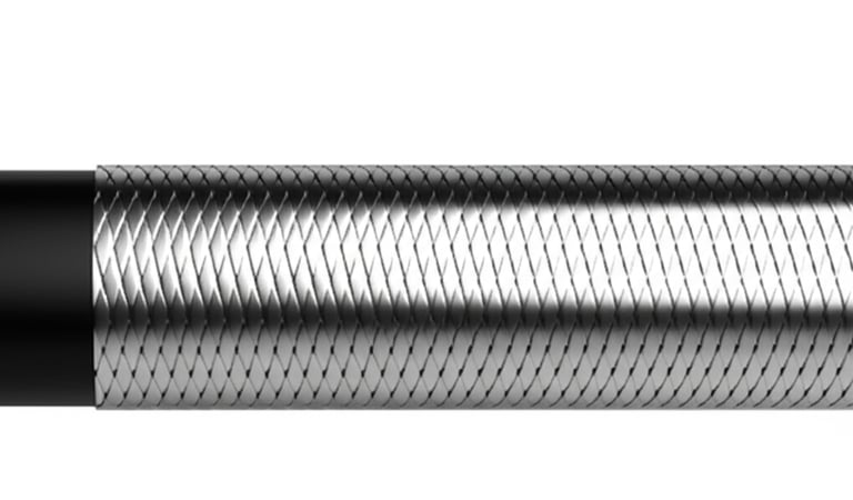
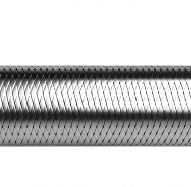
Braid Shield
Braid shielding consists of interwoven copper wires forming a mesh structure around the cable conductors. This construction provides excellent mechanical robustness and flexibility while maintaining effective EMI protection, particularly against low-frequency interference.
The advantages of braid shield applications include mechanical strength and flexibility, making them well-suited for applications where cables may be subject to movement or mechanical stress. The woven copper construction can withstand repeated bending, twisting, and vibration without losing its protective properties. This durability is particularly valuable in braid shield applications within port environments where cables may be exposed to equipment vibration, thermal expansion and contraction, and occasional physical contact.
Braid shields also provide good low-frequency EMI protection, which is important for controlling harmonics and other low-frequency disturbances common in power systems. The multiple current paths created by the interwoven conductors help distribute electromagnetic currents and reduce the shield's impedance at lower frequencies.
The primary disadvantages of braid shielding include incomplete coverage and higher cost. Typical braid shields provide coverage ranging from 70% to 90%, leaving small gaps that can allow some electromagnetic energy to penetrate or escape. While this coverage is adequate for many applications, it may not be sufficient for environments with extremely high EMI requirements.
Additionally, braid shields are heavier and more expensive than foil alternatives due to the greater amount of conductor material required. The manufacturing process is also more complex, contributing to higher costs.
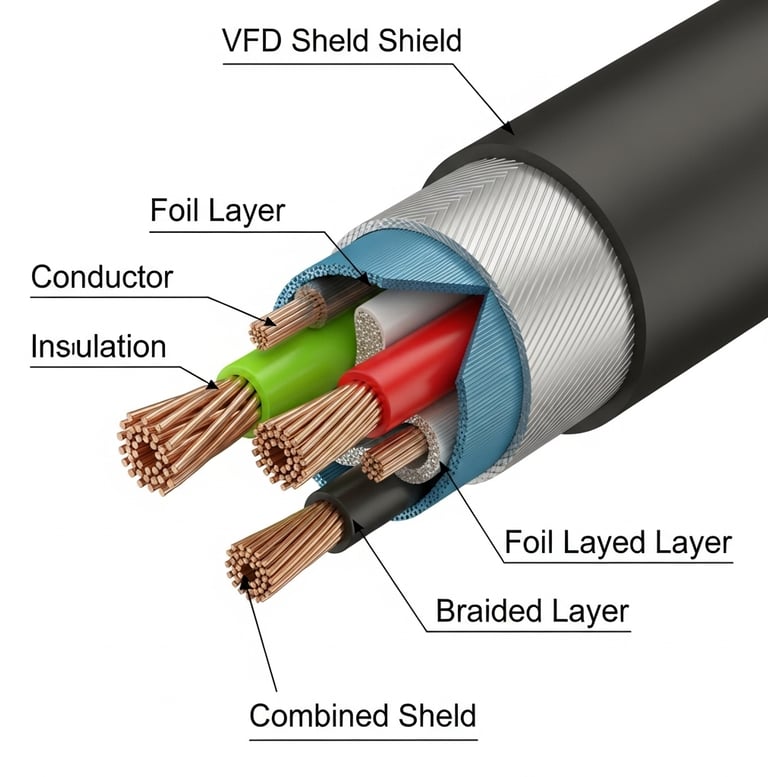
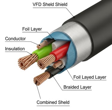
Combined Shield (Foil + Braid)
Combined shielding systems incorporate both foil and braid elements to provide comprehensive EMI protection across both low and high frequencies. This approach leverages the strengths of each shielding method while mitigating their individual limitations.
The foil component provides excellent high-frequency protection and nearly 100% coverage, while the braid component contributes mechanical strength, flexibility, and enhanced low-frequency performance. This combination results in superior overall EMI protection compared to either shielding method used alone.
Combined shields are particularly well-suited for VFD applications requiring comprehensive EMI shielding, especially in demanding environments like ports where multiple frequency ranges must be controlled simultaneously. The dual-layer construction provides redundancy, ensuring that if one shield component is compromised, the other continues to provide protection.
The primary disadvantages of combined shielding include increased cost, weight, and cable diameter. The additional materials and manufacturing complexity result in higher costs compared to single-shield alternatives. The larger cable diameter may also create installation challenges in applications with limited space.
Suitability for Port Cable Installations
When evaluating shield types for port cable installations, several factors must be considered. The harsh marine environment favors mechanically robust solutions that can withstand corrosion, mechanical stress, and temperature extremes. Combined shields offer the best overall performance for these challenging conditions, providing comprehensive EMI protection with enhanced mechanical durability.
For fixed installations with minimal mechanical stress, foil shields may be adequate and cost-effective. However, the marine environment's corrosive nature and potential for mechanical disturbance generally favor more robust solutions.
Braid shields alone may be suitable for applications where high-frequency EMI is not a primary concern, but the broad frequency spectrum of modern port electrical systems typically requires more comprehensive protection.
Environmental Factors Influencing the Selection of Shielding Materials for VFD Cables
Material Conductivity and Durability Comparison
The selection of shielding materials for port VFD cable applications requires careful consideration of electrical conductivity, mechanical properties, and environmental resistance. The three primary materials used in cable shielding are copper, aluminum, and coated materials, each offering distinct advantages and limitations.
Copper represents the gold standard for cable shielding due to its excellent electrical conductivity, second only to silver among commonly available metals. This high conductivity translates to superior EMI protection across a broad frequency range, making copper shields highly effective for VFD applications. Copper also offers good mechanical properties, including flexibility and resistance to fatigue failure, which are important for cables that may be subject to movement or vibration.
However, copper's susceptibility to corrosion in marine environments presents significant challenges for port applications. Salt spray and high humidity can lead to copper oxidation, which increases resistance and reduces shielding effectiveness over time. This degradation can compromise the cable's EMI protection and potentially lead to system failures.
Aluminum shielding offers advantages in weight reduction and cost-effectiveness compared to copper alternatives. The lower density of aluminum results in lighter cables, which can be beneficial for overhead installations or applications where weight is a critical factor. Additionally, aluminum is generally less expensive than copper, making it attractive for large-scale installations.
The primary disadvantage of aluminum shielding is its lower electrical conductivity compared to copper, which can result in reduced EMI protection effectiveness. Aluminum is also more susceptible to corrosion in certain environments, and its oxide layer, while providing some protection, can increase contact resistance and degrade electrical performance.
Coated materials, particularly copper with tin or silver coatings, offer enhanced corrosion resistance while maintaining the electrical advantages of copper. Tin-coated copper provides excellent protection against marine corrosion while preserving the underlying copper's conductivity. Silver-coated copper offers even better electrical performance but at significantly higher cost.
Port Environmental Factors
Port environments present unique challenges that significantly influence shielding material selection. Salt spray represents one of the most significant threats to cable performance, as it can accelerate corrosion processes and create conductive paths that can compromise shielding effectiveness. The high chloride content in marine atmospheres is particularly aggressive toward most metals, requiring careful material selection and protective measures.
Temperature extremes in port environments can affect shielding material properties and performance. Thermal cycling between hot daytime temperatures and cooler nighttime conditions can cause expansion and contraction stresses that may lead to shield degradation over time. Additionally, extreme temperatures can affect the electrical properties of shielding materials, potentially altering their EMI protection characteristics.
Mechanical stress from cargo handling equipment, wind loads, and structural movement represents another significant environmental factor. Cables in port environments may be subject to vibration, impact, and tensile loads that can damage inadequately designed shields. The shielding system must be robust enough to maintain its integrity under these conditions while providing consistent EMI protection.
UV radiation exposure is another consideration for cables installed in outdoor port environments. While shielding materials are typically protected by outer cable jackets, any exposure to UV radiation can cause degradation of both the shielding materials and the cable's protective systems.
Grounding Techniques for VFD Cable Shields and Their Impact on Port Cable Systems
Understanding VFD cable shield grounding methods is crucial for effective EMI control in port applications. The choice between different grounding strategies for port cables significantly impacts system performance and interference control.
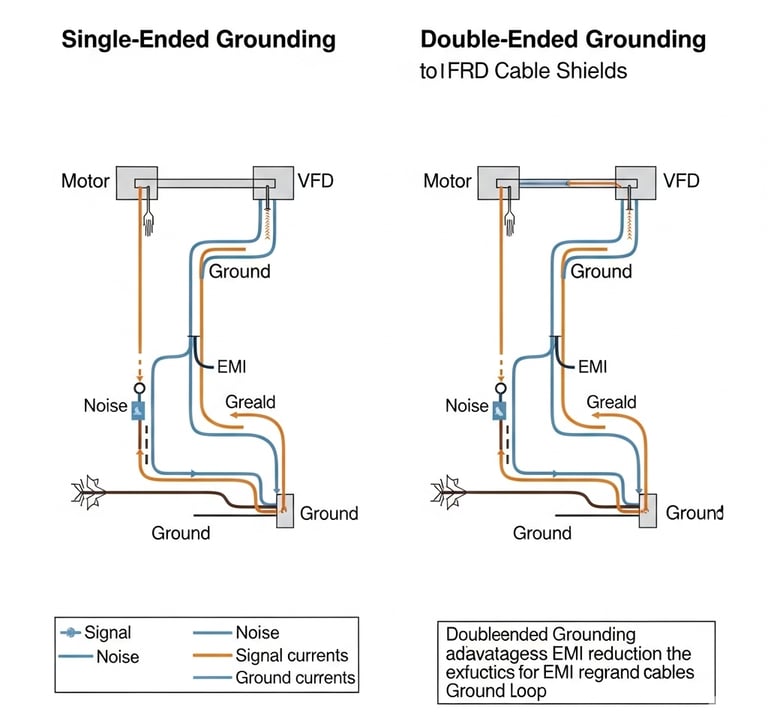
Single-Ended Grounding
Single-ended grounding involves connecting the cable shield to ground at one end only, typically at the source end of the cable. This VFD cable shield grounding method offers several advantages, particularly in terms of preventing ground loops and controlling low-frequency EMI.
When comparing single-ended vs. double-ended grounding, the primary benefit of single-ended grounding is the prevention of ground loops, which can occur when the shield is connected to ground at multiple points with different electrical potentials. Ground loops can create circulating currents that generate magnetic fields and contribute to EMI problems. By grounding the shield at only one end, these circulating currents are eliminated, reducing the potential for low-frequency interference.
Single-ended grounding is particularly effective for controlling low-frequency EMI, including power frequency harmonics and other low-frequency disturbances common in VFD systems. The grounding connection provides a low-impedance path for these currents, directing them away from sensitive equipment and reducing their impact on system performance.
However, in the single-ended vs. double-ended grounding comparison, single-ended grounding has limitations in high-frequency applications. At higher frequencies, the shield's impedance increases, reducing its effectiveness in controlling high-frequency EMI. This limitation can be significant in port environments where multiple high-frequency sources may be present.
Double-Ended Grounding
Double-ended grounding connects the cable shield to ground at both ends, providing superior high-frequency EMI protection compared to single-ended grounding. This VFD cable shield grounding method is particularly effective for controlling high-frequency disturbances generated by VFD switching operations.
The primary advantage of double-ended grounding is its superior high-frequency performance. By providing ground connections at both ends of the cable, the shield's effective impedance is reduced at higher frequencies, improving its ability to control high-frequency EMI. This enhanced performance is particularly valuable in port environments where multiple high-frequency sources may create complex electromagnetic conditions.
Double-ended grounding also provides redundancy in the grounding system. If one ground connection is compromised, the other continues to provide EMI protection, enhancing system reliability.
The main disadvantage of double-ended grounding is the risk of ground loops, which can cause low-frequency interference problems. When the shield is grounded at both ends, differences in ground potential can create circulating currents that generate magnetic fields and contribute to EMI. This risk is particularly significant in large port installations where ground potential differences may be substantial.
Grounding Strategies for Port Cables
For port VFD cable applications, the selection of appropriate grounding strategies for port cables depends on several factors, including cable length, frequency spectrum of concern, and ground system design. In general, double-ended grounding is recommended for high-frequency EMI environments typical of ports, provided that proper ground system design is implemented to minimize ground loop risks.
For longer cables where high-frequency EMI is a primary concern, double-ended grounding with impedance bonding may be appropriate. This approach uses impedance elements to provide high-frequency grounding while blocking low-frequency circulating currents.
Proper ground system design is crucial for effective shield grounding in port applications. This includes maintaining low ground resistance, minimizing ground potential differences, and providing adequate ground fault protection. Regular inspection and maintenance of ground connections are also essential to ensure continued effectiveness.
The Relationship Between Cable Length, Frequency, and EMI Impact in Port Cable Design
Understanding the VFD cable length impact on EMI is crucial for effective long-distance port cable design. The relationship between cable length and EMI impact is fundamentally governed by the cable's electrical characteristics, particularly its capacitance and inductance.
Cable Capacitance and Inductance Considerations
As cable length increases, both capacitance and inductance increase proportionally, leading to more complex electromagnetic behavior and potentially greater EMI challenges. These cable capacitance and inductance considerations become critical factors in long-distance port cable design.
The VFD cable length impact on EMI is particularly evident in how cable capacitance affects the high-frequency response of the cable, creating impedance changes that can lead to signal reflections and standing wave patterns. These effects become more pronounced at higher frequencies and longer cable lengths, potentially causing increased EMI emissions and reduced signal quality.
The capacitance per unit length of a cable is determined by the geometry of the conductors and the dielectric properties of the insulation material. These cable capacitance and inductance considerations are expressed through the formula:
C = (2 × π × ε) / ln(D/d)
Where ε is the dielectric constant of the insulation, D is the distance between conductor centers, and d is the diameter of the conductor. This relationship shows that capacitance increases with better dielectric materials and closer conductor spacing.
Cable inductance affects the low-frequency response and influences the cable's characteristic impedance. Higher inductance can lead to increased voltage drops and phase shifts, which can affect VFD performance and potentially increase EMI emissions. The inductance per unit length is given by:
L = (μ / 2 × π) × ln(D/d)
Where μ is the magnetic permeability of the medium. This formula shows that inductance increases with greater conductor separation and higher permeability materials.
Harmonic Distortion and EMI Amplification
The VFD cable length impact on EMI is further demonstrated through how longer cables can amplify harmonic distortion and EMI through resonance effects and impedance mismatches. The distributed capacitance and inductance of long cables can create resonant frequencies where small input signals are amplified, potentially causing significant EMI problems.
These resonance effects are particularly problematic in VFD systems, where the switching frequencies and their harmonics can coincide with cable resonant frequencies. When this occurs, the cable effectively becomes an antenna, radiating electromagnetic energy and potentially interfering with nearby equipment.
Design Strategies for Long-Distance Port Cable Design
To mitigate the EMI effects of long cables in port applications, several long-distance port cable design strategies can be employed. Proper cable routing and installation techniques can minimize EMI problems while maintaining system performance.
One effective approach is to use intermediate grounding points along long cable runs. This technique helps control the build-up of electromagnetic energy and reduces the effective electrical length of the cable. However, care must be taken to avoid creating ground loops that could cause additional problems.
Another strategy involves the use of filters and impedance matching devices at strategic points along the cable run. These devices can help control reflections and reduce the amplitude of resonant effects, improving overall system performance.
Cable bundling and segregation techniques can also be effective in reducing EMI in long cable runs. By grouping cables with similar characteristics and separating them from sensitive circuits, the potential for interference can be reduced.
In port applications, where cable runs may be particularly long due to the large scale of the facilities, careful planning of cable routes and installation methods is essential. This includes considering the proximity of sensitive equipment, the presence of other electromagnetic sources, and the need for maintenance access.
Challenges and Solutions for Applying VFD Cables in Port Environments
Port VFD Cable Application Challenges
Port environments present unique port VFD cable application challenges that extend beyond typical industrial settings. The corrosive marine atmosphere, with its high salt content and humidity, creates an aggressive environment that can rapidly degrade cable components and compromise performance. This corrosion affects not only the cable's outer jacket but can also penetrate to the shielding layers, reducing their effectiveness and potentially leading to system failures.
These port VFD cable application challenges are compounded by temperature extremes that can be particularly problematic for cable systems. The combination of direct sunlight, radiant heat from large metal structures, and the thermal mass of the ocean creates significant temperature variations that can stress cable components. These temperature cycles can cause expansion and contraction of cable materials, leading to mechanical stress and potential failure of critical components.
Mechanical wear from cargo handling equipment, vehicle traffic, and structural movement represents another significant challenge. Cables in port environments may be subject to impact loads, vibration, and abrasion that can damage protective jackets and compromise shielding integrity. The large scale of port operations means that cable systems may be subject to these stresses over extended periods, requiring robust designs to maintain performance.
The high EMI port environment creates additional challenges for VFD cable applications. The concentration of electrical equipment, including cranes, conveyors, lighting systems, and communication equipment, creates a complex electromagnetic environment where multiple sources of interference can interact. This electromagnetic complexity requires careful consideration of shielding design and installation practices to ensure effective EMI control.
High EMI Port Environment Solutions
To address the port VFD cable application challenges, several high EMI port environment solutions can be implemented. The use of combined shielding systems (foil plus braid) provides comprehensive EMI protection while offering the mechanical robustness needed for port environments. This approach leverages the strengths of both shielding methods to provide superior performance in demanding conditions.
Port cable shielding optimization involves the selection of corrosion-resistant materials that are essential for port cable applications. The use of tin-coated or silver-coated copper shielding provides enhanced resistance to marine corrosion while maintaining excellent electrical properties. Additionally, the selection of appropriate jacket materials that can withstand UV radiation, salt spray, and temperature extremes is crucial for long-term performance.
These high EMI port environment solutions also include proper installation techniques that are critical for maintaining cable performance in port environments. This includes the use of appropriate cable supports, protection from physical damage, and proper sealing of cable entries to prevent moisture ingress. Regular inspection and maintenance programs are also essential components of port cable shielding optimization to identify and address potential problems before they lead to system failures.
Environmental protection measures, such as the use of cable conduits, protective covers, and proper drainage systems, can help extend cable life and maintain performance in challenging port conditions. These measures should be designed to accommodate the specific environmental conditions present at each port location.
Relevant Standards and Compliance Requirements Guiding Port VFD Cable Design
VFD Cable Standards Framework
The design and application of VFD cables in port environments must comply with various VFD cable standards that address different aspects of cable performance and safety. These standards provide the technical foundation for ensuring that cables meet the requirements for port cable EMC compliance, electrical performance, and safety in demanding applications.
Understanding VFD cable standards is crucial for proper cable selection and installation. IEC 62153-4-3 addresses shielding effectiveness testing and requirements for communication and control cables. This standard defines test methods for measuring how effectively a cable shield prevents electromagnetic interference from penetrating into or escaping from the cable. The standard specifies measurement procedures and performance criteria that are essential for evaluating VFD cable suitability for port applications.
Shielding effectiveness is measured in decibels (dB) and represents the ratio of the electromagnetic field strength without shielding to the field strength with shielding. The formula for shielding effectiveness is:
SE = 20 × log10(E_unshielded / E_shielded)
Where E_unshielded is the electric field without shielding and E_shielded is the electric field with shielding. Higher values indicate better shielding performance, with combined shields typically achieving values exceeding 60 dB.
IEC 62153-4-4 focuses on transfer impedance testing, which measures the efficiency of a shield in containing or blocking electromagnetic currents. Transfer impedance is defined as the ratio of the voltage induced across the shield to the current flowing through the shield:
Zt = V_shield / I_current
Lower transfer impedance values indicate better shielding performance, particularly at high frequencies where VFD switching can create significant electromagnetic disturbances.
IEC 60287 covers the thermal and electrical performance of power cables, including aspects relevant to VFD applications. This standard addresses current-carrying capacity, voltage ratings, and thermal performance under various operating conditions. Compliance with this standard ensures that cables can safely carry the required currents while maintaining their electrical properties under normal and fault conditions.
Port Cable EMC Compliance Requirements
Port cable EMC compliance is particularly important for port VFD cable applications due to the complex electromagnetic environment and the need to prevent interference with sensitive equipment. EMC compliance ensures that cables neither cause nor are susceptible to electromagnetic interference that could disrupt port operations.
The EMC requirements for port applications typically include both emission and immunity standards. Emission standards limit the amount of electromagnetic energy that cables can radiate, while immunity standards ensure that cables can operate properly in the presence of electromagnetic disturbances from other sources.
IEC and UL certification for cables may also apply to port VFD cable installations, particularly in North American markets. UL standards address safety aspects including fire resistance, mechanical properties, and electrical performance under fault conditions. Compliance with IEC and UL certification for cables requirements is often necessary for insurance purposes and may be required by local codes and regulations.
Importance of VFD Cable Standards Compliance
Compliance with VFD cable standards is essential for several reasons beyond basic technical performance. Safety considerations are paramount in port environments where cable failures could lead to equipment damage, operational disruptions, or personnel injury. Standards compliance provides assurance that cables have been tested and proven to meet minimum safety requirements.
Insurance requirements often mandate compliance with specific VFD cable standards, and failure to meet these requirements can void coverage or result in higher premiums. Given the high value of port equipment and the potential costs of operational disruptions, maintaining insurance coverage is crucial for port operators.
Port cable EMC compliance may also be required by local authorities, particularly for cables used in critical infrastructure applications. Port facilities are often subject to stringent safety and environmental regulations that require the use of compliant equipment and materials.
From a practical standpoint, standards compliance provides a common basis for evaluating and comparing different cable options. It also ensures that cables from different manufacturers will have similar performance characteristics and can be used interchangeably when necessary.
Conclusion: Are VFD Cables Suitable for Port Power Cable Applications?
Based on the comprehensive analysis of VFD cable design, performance characteristics, and environmental considerations, VFD cables can indeed be suitable for port power cable applications when properly designed and selected for the specific challenges of the marine environment. The key to successful implementation lies in understanding the unique requirements of port environments and selecting appropriate cable designs that address these challenges.
The critical factors for successful VFD cable application in ports include the selection of appropriate shielding types, typically combined shields that provide comprehensive EMI protection across both low and high frequencies. The harsh marine environment requires corrosion-resistant materials, such as tin-coated copper shielding, and robust mechanical designs that can withstand the physical stresses common in port operations.
Proper grounding techniques are essential for effective EMI control in port applications. While the choice between single-ended and double-ended grounding depends on specific application requirements, double-ended grounding is generally recommended for the high-frequency EMI environments typical of ports, provided that proper ground system design is implemented to minimize ground loop risks.
The relationship between cable length, frequency, and EMI impact must be carefully considered in port cable design. The large scale of port facilities often requires long cable runs that can amplify EMI effects through resonance and impedance mismatches. Proper design strategies, including intermediate grounding points and impedance matching, can help mitigate these effects.
Compliance with relevant international standards is crucial for ensuring safety, reliability, and insurability of port VFD cable installations. Standards such as IEC 62153-4-3, IEC 62153-4-4, and IEC 60287 provide the technical foundation for evaluating cable performance and ensuring that installations meet minimum requirements for electromagnetic compatibility and electrical performance.
Practical Recommendations for Port VFD Cable Selection and Design
For port operators and engineers considering VFD cable applications, several practical recommendations can help ensure successful implementation:
Prioritize combined shielding systems that provide comprehensive EMI protection while offering the mechanical robustness needed for port environments.
Select corrosion-resistant materials including tin-coated or silver-coated copper shielding and appropriate jacket materials that can withstand marine conditions.
Implement proper grounding strategies with emphasis on maintaining low ground resistance and minimizing ground potential differences throughout the port facility.
Consider cable routing and installation techniques that minimize exposure to physical damage while maintaining EMI control effectiveness.
Establish regular inspection and maintenance programs to monitor cable condition and address potential problems before they lead to system failures.
Ensure compliance with relevant standards including IEC and UL requirements for electromagnetic compatibility and safety.
Work with experienced suppliers who understand the unique requirements of port applications and can provide technical support throughout the installation and operational phases.
When properly designed, selected, and installed, VFD cables can provide reliable, interference-free operation in port power cable applications. The key is to approach each installation with a thorough understanding of the environmental challenges and technical requirements, ensuring that the selected cable system is optimized for the specific conditions and operational requirements of the port facility.
The investment in properly designed VFD cable systems pays dividends in terms of reduced maintenance costs, improved operational reliability, and enhanced safety for port operations. As port facilities continue to modernize and expand, the importance of reliable cable systems that can operate effectively in challenging environments will only continue to grow.
How to Reach Us
Get in Touch
SiteMap
Product Catalogue
Festoon Cable
Shore Power Cable


Scan to add us on WeChat