📞+86 153 7530 2641 📧 hongjing.Wang@feichuncables.com

What is the Fleet Angle During Cable Unwind for Mobile Applications? Understanding Fleet Angle in Reeling Cable Systems
Discover the importance of managing fleet angle during cable unwind for mobile applications. Learn how to calculate the fleet angle, understand its impact on cable wear, and explore preventive measures to ensure smooth cable management in dynamic environments.
hongjing.Wang@Feichun
7/30/202512 min read
Introduction
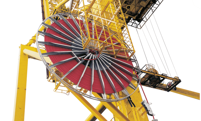
In the demanding world of mobile machinery operations, cable management systems face unique challenges that stationary installations rarely encounter. Whether dealing with crane hoisting cables, spreader basket lifting systems, or robotic arm power feeds, the fleet angle during cable unwind represents one of the most critical parameters determining operational success and equipment longevity.
Fleet angle management becomes particularly crucial in mobile applications where dynamic forces, varying load conditions, and constant repositioning create complex stress patterns on cable systems. Mobile cranes, for instance, must maintain optimal cable spooling while operating under changing boom angles, wind loads, and ground conditions. Similarly, automated guided vehicles (AGVs) with trailing cable systems require precise fleet angle control to prevent cable damage during rapid directional changes.
The significance of proper fleet angle management extends beyond mere equipment protection. In mobile applications, cable failure can result in catastrophic accidents, costly downtime, and regulatory compliance issues. Modern mobile machinery increasingly relies on sophisticated electrical and hydraulic systems that demand uninterrupted cable integrity. Understanding and implementing proper fleet angle principles ensures reliable operation while maximizing the return on investment in expensive mobile equipment.
This comprehensive analysis explores the fundamental principles of fleet angle in mobile cable systems, providing practical insights for engineers, technicians, and operators working with dynamic cable management challenges. From basic calculations to advanced preventive strategies, this guide addresses the critical aspects of maintaining optimal cable performance in mobile environments.
What is Fleet Angle?
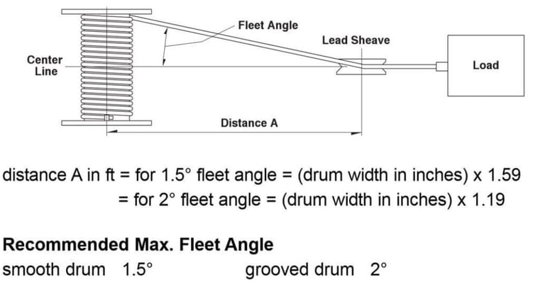
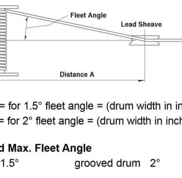
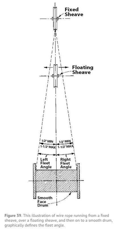
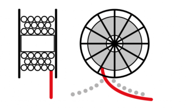
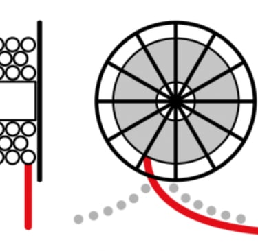
Fleet angle represents the angular relationship between a cable's departure path from its storage reel and the perpendicular centerline of that reel. This seemingly simple geometric relationship plays a fundamental role in determining how smoothly cables wind and unwind during operation, directly impacting equipment reliability and cable service life.
In technical terms, fleet angle is measured as the included angle between two distinct reference lines: the perpendicular line extending from the drum's axis through the center of the fixed sheave or guide point, and the line connecting the drum's flange edge to the cable's exit point at the guide mechanism. This measurement varies continuously as the cable unwinds, creating different stress patterns across the cable's cross-section.
The physics behind fleet angle influence on cable behavior involves several interconnected factors. As the fleet angle increases, the cable experiences lateral forces that can cause uneven spooling, where successive cable layers fail to lay uniformly against previous wraps. This uneven distribution creates high-stress concentration points that accelerate cable wear and can lead to premature failure.
Wire rope and cable construction significantly affects fleet angle sensitivity. Multi-strand cables with flexible outer jackets generally tolerate moderate fleet angle variations better than rigid single-conductor cables. However, even flexible cables experience reduced service life when subjected to excessive fleet angles over extended operating periods.
The relationship between fleet angle and cable tension also deserves consideration. Higher cable tensions tend to amplify the negative effects of improper fleet angles, while lighter loads may mask fleet angle problems until they become severe. This characteristic makes fleet angle management particularly challenging in variable-load mobile applications where tension levels fluctuate continuously.
Understanding fleet angle behavior requires recognizing that cable storage drums and reels create essentially helical winding patterns. The fleet angle determines the pitch of this helix, with optimal angles producing uniform, stable cable layers that minimize internal stress and external wear points.
Recommended Fleet Angle Range for Mobile Applications
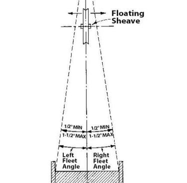
Establishing appropriate fleet angle parameters for mobile applications requires balancing multiple operational factors while adhering to established engineering standards. The universally accepted optimal fleet angle range of 0.5° to 1.5° provides the foundation for reliable cable management across diverse mobile equipment types.
This narrow operational window reflects decades of field experience and laboratory testing across various cable types and operating conditions. Within this range, cables experience minimal lateral stress while maintaining adequate cross-drum travel to ensure even spooling. The lower bound of 0.5° prevents cable pile-up scenarios where insufficient lateral movement causes successive wraps to stack vertically rather than spreading across the drum width.
Excessive fleet angles exceeding 1.5° create multiple operational problems that can quickly escalate into equipment failures. Uneven spooling represents the most immediate concern, where cables fail to distribute evenly across the drum width, creating thick and thin sections that generate unbalanced loads and vibrations. These imbalances propagate through the entire cable system, affecting guide mechanisms, tensioning devices, and drive systems.
Cable wear acceleration occurs when excessive fleet angles force cables to bend repeatedly through sharp angles during winding and unwinding cycles. This repetitive flexing concentrates stress at specific points along the cable length, leading to fatigue failures that often occur without warning. In mobile applications where cables experience thousands of cycles daily, this accelerated wear can reduce cable life by 50% or more.
Misalignment, tangling, and overlapping issues frequently develop when fleet angles exceed recommended limits. Mobile equipment operating in challenging environments cannot afford the downtime associated with cable jams or tangled systems. These problems often require manual intervention, exposing personnel to safety risks while disrupting operational schedules.
Insufficient fleet angles below 0.5° present different but equally problematic challenges. Cable pile-up occurs when insufficient lateral movement causes new cable wraps to stack directly on previous layers, creating unstable cable formations that can suddenly shift or collapse. This instability generates shock loads that stress the entire cable system and can damage drum flanges or guide mechanisms.
Tension distribution problems also arise from inadequate fleet angles. When cables pile up in narrow sections of the drum, localized high-tension areas develop while other drum sections remain underutilized. This uneven loading pattern reduces effective cable capacity and can overstress drum mounting systems.
Mobile applications face additional fleet angle challenges due to dynamic operating conditions. Equipment motion, vibration, and varying load conditions can cause fleet angles to fluctuate beyond static design calculations. Successful mobile cable systems incorporate design margins and active management systems to maintain optimal fleet angles despite these dynamic influences.
Formula for Calculating Fleet Angle
Accurate fleet angle calculation provides the foundation for designing effective mobile cable systems and troubleshooting existing installations. The fundamental formula for determining fleet angle utilizes basic trigonometric relationships:
θ = arctan(W / D)
Where the variables represent:
θ = Fleet angle in degrees or radians
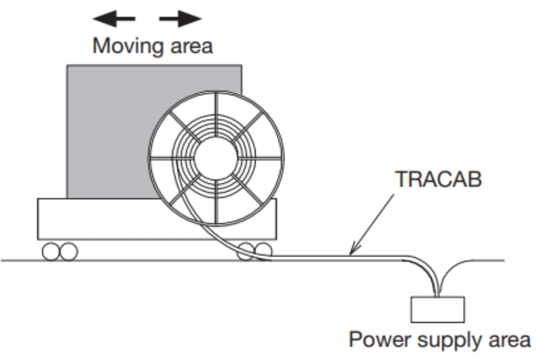
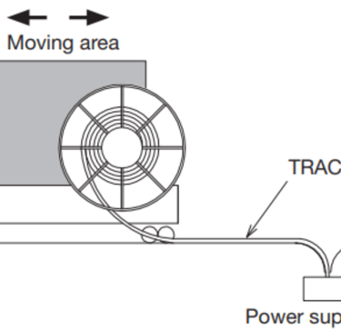
W = Horizontal distance from the reel flange to the cable guiding point
D = Distance from the cable reel centerline to the guiding point
This calculation assumes a two-dimensional analysis where the cable travels in a single plane from the drum to the guide point. For mobile applications, this simplified approach provides adequate accuracy for most design purposes, though complex three-dimensional cable paths may require more sophisticated analysis.
Practical application of this formula requires careful measurement of the geometric parameters. The horizontal distance (W) represents the maximum lateral displacement the cable experiences as it travels across the full width of the storage drum. This measurement changes continuously as the cable unwinds, with maximum values occurring when the cable exits from the drum's extreme edges.
The guiding distance (D) represents the straight-line distance from the drum's centerline to the first cable guide point, whether that's a fixed sheave, roller assembly, or other directional control device. This measurement remains relatively constant in most installations, though mobile equipment may experience variations due to boom extensions, articulated joints, or other geometric changes.
Dynamic considerations in mobile applications require understanding how these parameters change during operation. Mobile cranes experience significant geometry changes as booms extend and retract, requiring fleet angle calculations across the full range of operating positions. Similarly, robotic systems with multiple degrees of freedom must maintain acceptable fleet angles throughout their entire operational envelope.
Multiple-layer calculations become necessary when dealing with large cable capacities common in mobile applications. As cable builds up on the drum, the effective drum diameter increases, altering the geometric relationships and fleet angles. Advanced calculations must account for cable layer buildup to ensure fleet angles remain within acceptable limits throughout the entire cable capacity.
Safety factors should be incorporated into fleet angle calculations for mobile applications. The dynamic nature of mobile equipment operation, combined with potential measurement uncertainties and component wear, justifies designing for fleet angles well within the optimal range rather than at the boundary limits.
Engineers frequently use graphical methods or computer-aided design tools to visualize fleet angle variations across the full range of cable travel. These tools help identify potential problem areas and optimize component positioning to maintain ideal fleet angles throughout the operating cycle.
Factors Affecting Fleet Angle
Understanding the multiple variables that influence fleet angle behavior enables engineers and operators to optimize mobile cable systems for maximum reliability and performance. These factors interact in complex ways, requiring systematic analysis to achieve optimal results.
Reel width represents the primary geometric factor influencing fleet angle characteristics. Wider reels naturally produce smaller fleet angles for any given guiding distance, as the cable travels a longer path across the drum face before reaching the maximum angular displacement. This relationship makes reel width selection critical in space-constrained mobile applications where guiding distances are limited by equipment geometry.
However, wider reels also present challenges in mobile applications. Increased reel width requires more installation space, adds weight to mobile platforms, and may conflict with other system components. The optimal reel width balances fleet angle requirements against these practical constraints, often requiring custom reel designs for specific mobile applications.
Guiding distance provides the most adjustable parameter for fleet angle optimization in existing installations. Increasing the distance between the cable reel and the first guide point directly reduces fleet angles, often providing the most cost-effective solution for fleet angle problems. Mobile equipment designers frequently incorporate adjustable guide systems that allow field optimization of guiding distances.
Space limitations in mobile applications often constrain guiding distance options. Compact mobile platforms may not accommodate ideal guiding distances, requiring alternative approaches such as multiple guide points, specialized reel designs, or enhanced cable flexibility specifications.
Cable flexibility characteristics significantly impact fleet angle tolerance. Highly flexible cables with multiple small conductors or fiber optic elements generally accommodate larger fleet angles better than rigid single-conductor cables or stiff hydraulic lines. However, flexibility comes at the cost of durability, current-carrying capacity, or pressure ratings, requiring careful balance between fleet angle tolerance and functional requirements.
Advanced cable designs specifically engineered for mobile applications often incorporate enhanced flexibility features while maintaining necessary electrical or hydraulic performance. These specialized cables may justify their higher initial cost through extended service life and reduced maintenance requirements in challenging fleet angle environments.
Environmental factors unique to mobile applications also influence fleet angle behavior. Temperature variations affect cable flexibility and reel dimensions, potentially altering fleet angle characteristics throughout operating cycles. Vibration and shock loads can cause temporary fleet angle excursions beyond calculated values, requiring robust system designs that accommodate these dynamic conditions.
Cable tension levels interact with fleet angle effects in complex ways. Higher tensions tend to amplify fleet angle problems by increasing the forces acting on cable bends and guide points. Mobile applications with variable load conditions must consider fleet angle behavior across the full range of expected tensions, not just nominal operating values.
Impact of Fleet Angle in Mobile Applications
Mobile applications present unique challenges for fleet angle management due to their dynamic operating environments, variable load conditions, and space constraints. Understanding these impacts enables better system design and more effective maintenance strategies.
Dynamic motion effects represent the most significant difference between mobile and stationary cable applications. Mobile cranes, for example, experience boom rotation, extension, and lifting motions that continuously alter the geometric relationships affecting fleet angle. These changes can cause fleet angles to vary significantly during normal operation, requiring systems designed to accommodate this variability.
The acceleration and deceleration forces common in mobile equipment create additional stresses on cable systems already challenged by fleet angle considerations. Quick starts and stops can cause cable surge effects that temporarily increase effective fleet angles beyond calculated static values. Mobile system designs must account for these dynamic load factors to prevent cable damage.
Vibration and shock loading in mobile environments compound fleet angle-related stress patterns. Road travel, engine vibration, and operational impacts create high-frequency stress cycles that accelerate cable fatigue, particularly in areas where fleet angle creates stress concentrations. This combination often reduces cable life significantly compared to equivalent stationary installations.
Guide pulleys and roller systems become critical components in mobile fleet angle management. These devices help maintain controlled cable paths despite equipment motion and geometric changes. However, mobile applications often subject guide systems to higher loads and more demanding environmental conditions than stationary installations, requiring robust design and frequent maintenance.
Advanced mobile systems increasingly incorporate active cable management technologies such as motorized guide systems, tension monitoring, and automatic fleet angle compensation. These systems can maintain optimal cable positioning despite changing operating conditions, though they add complexity and potential failure points that require careful evaluation.
Multi-axis cable systems common in robotic applications create three-dimensional fleet angle challenges that exceed simple two-dimensional calculations. These systems require sophisticated analysis and often incorporate specialized cable designs optimized for complex bending patterns and multiple simultaneous motions.
The safety implications of fleet angle problems in mobile applications often exceed those in stationary systems. Cable failures in mobile cranes or aerial work platforms can result in catastrophic accidents with severe injury potential. This safety-critical nature demands conservative design approaches and rigorous maintenance protocols.
Operational efficiency impacts from poor fleet angle management include increased maintenance costs, reduced cable life, and unexpected downtime. Mobile equipment typically operates under tight scheduling constraints where unplanned maintenance creates significant economic penalties. Proper fleet angle management helps ensure reliable operation and predictable maintenance schedules.
Preventive Measures for Managing Fleet Angle
Implementing effective preventive measures for fleet angle management requires a comprehensive approach encompassing design optimization, component selection, installation practices, and ongoing maintenance protocols. Mobile applications demand particularly robust preventive strategies due to their challenging operating environments.
Cable guide system installation represents the most fundamental preventive measure for fleet angle control. Properly designed guide systems maintain consistent cable paths despite equipment motion and load variations. Fixed guide sheaves provide reliable directional control but require careful positioning to ensure optimal fleet angles throughout the cable's travel range.
Adjustable guide systems offer flexibility for field optimization and adaptation to changing operational requirements. These systems allow technicians to fine-tune fleet angles based on actual operating conditions rather than theoretical calculations. However, adjustable systems require regular inspection and readjustment to maintain optimal performance.
Multi-point guiding strategies can be particularly effective in mobile applications where single guide points cannot accommodate the full range of required cable movements. Sequential guide points allow gradual directional changes that maintain acceptable fleet angles while accommodating complex cable paths. This approach requires careful coordination between guide points to prevent cable binding or excessive tension buildup.
Proper alignment procedures between reels and guiding mechanisms form the foundation of effective fleet angle management. Initial installation alignment must account for equipment tolerances, thermal expansion, and settling effects that can alter geometric relationships over time. Mobile equipment mounting systems must maintain this alignment despite vibration, shock loading, and operational stresses.
Alignment verification should be performed using precision measurement tools rather than visual estimation. Laser alignment systems, dial indicators, and electronic measurement devices provide the accuracy necessary for optimal fleet angle performance. Documentation of alignment procedures and measurements enables consistent maintenance practices and troubleshooting support.
Regular inspection and maintenance protocols must address both cable condition and system geometry. Visual inspection of cable spooling patterns can reveal fleet angle problems before they cause cable damage. Uneven wear patterns, loose spooling, or cable overlap indicate fleet angle issues requiring immediate attention.
Systematic measurement of key system dimensions helps identify gradual changes that could affect fleet angle performance. Component wear, mounting system looseness, or thermal effects can slowly alter system geometry, requiring periodic readjustment to maintain optimal performance.
Advanced monitoring systems increasingly incorporated in sophisticated mobile equipment provide continuous fleet angle monitoring and alert capabilities. Load cells, position sensors, and cable tension monitoring can detect fleet angle-related problems in real-time, enabling proactive maintenance and preventing catastrophic failures.
Preventive replacement strategies for cables operating in challenging fleet angle environments can significantly improve overall system reliability. Rather than waiting for cable failure, planned replacement based on operating hours, cycle counts, or condition assessments prevents unexpected downtime and potential safety incidents.
Training programs for operators and maintenance personnel ensure that fleet angle considerations are properly understood and implemented throughout the equipment lifecycle. Proper operation techniques, early problem identification, and correct maintenance procedures all contribute to effective fleet angle management in mobile applications.
Conclusion
Fleet angle management in mobile cable applications represents a critical intersection of mechanical engineering, materials science, and operational excellence. The narrow optimal range of 0.5° to 1.5° reflects the precise balance required between cable performance, system reliability, and practical design constraints inherent in mobile equipment applications.
The fundamental importance of maintaining proper fleet angles extends beyond simple cable longevity to encompass safety, operational efficiency, and economic performance. Mobile applications face unique challenges including dynamic loading, environmental exposure, and space constraints that demand sophisticated approaches to fleet angle management. Understanding these challenges and implementing appropriate preventive measures ensures reliable operation while maximizing return on investment in mobile cable systems.
Modern mobile equipment increasingly relies on complex cable systems for power transmission, control signals, and hydraulic functions. As these systems become more sophisticated and critical to operational success, proper fleet angle management becomes even more important. The integration of advanced monitoring systems, precision manufacturing techniques, and enhanced cable designs continues to improve fleet angle management capabilities in mobile applications.
The ongoing evolution of mobile equipment technology, including autonomous systems, electric powertrains, and advanced automation, will continue to challenge traditional approaches to fleet angle management. However, the fundamental principles outlined in this analysis will remain relevant, providing the foundation for addressing future challenges in mobile cable system design and operation.
Success in managing fleet angles for mobile applications requires commitment to proper design practices, quality installation procedures, and ongoing maintenance excellence. Organizations that prioritize these elements will achieve superior equipment reliability, enhanced safety performance, and improved operational efficiency in their mobile cable applications.
How to Reach Us
Get in Touch
SiteMap
Product Catalogue
Reeling Cable
Festoon Cable
Shore Power Cable


Scan to add us on WeChat