📞+86 153 7530 2641 📧 hongjing.Wang@feichuncables.com

What Is the Maximum Allowable Sidewall Pressure in Cable Bending, and How Is It Calculated?
Discover how to calculate the maximum allowable sidewall pressure in cable bending for port crane cables and industrial flexible cables. Learn key equations, cable configurations, and safety limits to ensure reliable installation and compliance with engineering standards.
hongjing.Wang@Feichun
7/23/202510 min read
Introduction
Cable bending is a critical consideration in electrical installations, particularly in demanding environments such as port facilities and industrial operations where cables must navigate complex routing paths. When cables are pulled through conduits or bent around corners during installation, they experience mechanical stresses that can significantly impact their performance and longevity. Among the most important of these stresses is sidewall pressure, a force that acts perpendicular to the cable's longitudinal axis during bending operations.
The significance of sidewall pressure becomes particularly pronounced in port crane cable installations and industrial flexible cable applications, where cables frequently encounter tight bends and must maintain reliable operation under continuous mechanical stress. Understanding and calculating the maximum allowable sidewall pressure is essential for ensuring cable integrity, preventing premature failure, and maintaining system reliability throughout the cable's operational life.
Proper calculation and adherence to sidewall pressure limits during cable routing is not merely a best practice but a fundamental requirement for safe and reliable electrical installations. Exceeding these limits can result in insulation damage, conductor deformation, and ultimately system failure, making this knowledge crucial for electrical engineers, installers, and maintenance personnel working with high-performance cable systems.
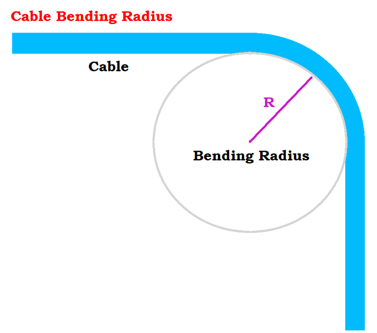
What Is Sidewall Pressure in Cable Bending?
Sidewall pressure, denoted as Pₛ in engineering calculations, represents the mechanical force exerted on a cable's outer jacket when the cable is bent around a curve or pulled through a conduit bend. This pressure is defined technically as the tension out of a bend expressed in newtons (or pounds) divided by the radius of the bend expressed in millimeters (or feet). The resulting measurement is expressed in units of newtons per meter (N/m) or pounds per foot (lb/ft) of radius.
The fundamental relationship governing sidewall pressure involves three critical parameters: cable tension during installation, the radius of the bend through which the cable passes, and a weight correction factor that accounts for the cable's own weight and its interaction with other cables in multi-cable installations. These factors combine to create a force that acts radially outward against the conduit wall or bend radius, potentially causing mechanical stress that can compromise the cable's structural integrity.
Cable tension, the primary driver of sidewall pressure, originates from the pulling force applied during installation. This tension varies throughout the cable run, typically reaching maximum values at the point where the cable exits a bend. The bend radius, conversely, acts as a mechanical advantage or disadvantage depending on its size – smaller radii concentrate forces more intensely, while larger radii distribute the same forces over a greater area, reducing the pressure per unit length.
The weight correction factor becomes particularly important in multi-cable installations where cables interact with each other and with the conduit walls in complex ways. This factor accounts for the additional forces created by cable weight distribution and the geometric constraints imposed by specific cable arrangements within the conduit or cable tray system.
Sidewall Pressure Calculation Methods
The calculation of sidewall pressure varies significantly depending on the cable configuration and the number of cables present in the installation. Four primary configurations are recognized in engineering practice, each requiring a specific calculation approach to accurately determine the maximum sidewall pressure experienced by the most critically loaded cable.
Single Cable in Conduit
For a single cable installation, the sidewall pressure calculation follows the most straightforward relationship:
P = T₀ / r (Equation J.5)
In this configuration, the cable experiences uniform pressure distribution around its circumference as it bends, with the maximum pressure occurring at the point of highest tension. This scenario is common in dedicated cable runs where only one cable traverses a particular conduit section.
Three Cables in Cradle Configuration
When three cables are installed in a cradle configuration, where one cable rests on top of two others, the center cable experiences the highest sidewall pressure due to its position and the additional support forces from the cables beneath it:
P = (3c - 2)T₀ / 3r (Equation J.6)
This configuration is frequently encountered in power distribution systems where three-phase power cables are grouped together. The center cable, being pressed hardest against the conduit wall, becomes the critical element for sidewall pressure calculations.
Three Cables in Triangular Configuration
In triangular arrangements where three cables are positioned with two cables at the bottom and one at the top, the sidewall pressure is distributed between the two bottom cables:
P = cT₀ / 2r (Equation J.7)
This configuration offers better load distribution compared to the cradle arrangement, as the pressure is shared between two cables rather than concentrated in a single cable.
Four Cables in Diamond Configuration
For four-cable diamond configurations, where cables are arranged in a diamond pattern within the conduit, the bottom cable experiences the greatest crushing force:
P = (3c - 2)T₀ / 3r (Equation J.8)
This arrangement is common in larger industrial installations where multiple power or control circuits must be routed together through the same conduit system.
In all these equations, the variables represent: P as the sidewall pressure in newtons per millimeter or pounds per foot of radius; T₀ as the tension out of the bend in newtons or pounds; c as the weight correction factor; and r as the inside radius of the bend in millimeters or feet.
The weight correction factor c varies based on cable characteristics and installation conditions, requiring careful consideration of cable weight, flexibility, and interaction with other system components.
What Is the Maximum Allowable Sidewall Pressure?
Industry standards establish specific maximum allowable sidewall pressure limits based on cable type, size, and construction characteristics. These limits are designed to prevent mechanical damage that could compromise cable performance or safety during installation and subsequent operation.
Standard Limits for Power Cables
For multiconductor power cables and single-conductor power cables of 6 AWG and larger, the maximum allowable sidewall pressure is established at 7300 N/m (500 lb/ft) of radius. This higher limit reflects the robust construction typical of larger power cables, which incorporate heavier insulation systems and more substantial jacket materials capable of withstanding greater mechanical stress.
Limits for Control and Smaller Power Cables
Control cables and single-conductor power cables of 8 AWG and smaller have a reduced maximum allowable sidewall pressure of 4380 N/m (300 lb/ft) of radius. This lower limit acknowledges the more delicate construction of these cables, which often feature thinner insulation and lighter jacket materials that require additional protection during installation.
Special Considerations for Instrumentation Cables
Instrumentation cables, due to their critical role in process control and monitoring systems, require individual manufacturer consultation to determine appropriate sidewall pressure limits. These cables often incorporate sensitive conductors and specialized insulation systems that may have unique mechanical limitations not covered by standard industry guidelines.
Manufacturer Verification Requirements
All sidewall pressure calculations and limits remain subject to verification by the cable manufacturer, who possesses detailed knowledge of the specific cable construction and materials. This requirement ensures that installation practices align with the manufacturer's design intentions and warranty conditions, providing additional assurance of long-term cable reliability.

Why Exceeding the Sidewall Pressure Limit Is Dangerous
Exceeding maximum allowable sidewall pressure limits poses significant risks to cable integrity and system reliability. The mechanical forces involved in cable bending create stress concentrations that can cause immediate damage during installation or contribute to long-term degradation that manifests as premature failure during operation.
Immediate Mechanical Damage
When sidewall pressure exceeds design limits, cables may experience crushing of the outer jacket, deformation of internal conductors, or compression of insulation materials. These forms of damage can create immediate performance issues, including increased electrical resistance, reduced current-carrying capacity, and compromised insulation integrity that may lead to ground faults or short circuits.
Long-Term Reliability Issues
Even when excessive sidewall pressure does not cause immediate visible damage, it can create stress concentrations that accelerate cable aging and increase the likelihood of future failures. Compressed insulation materials may develop micro-cracks that allow moisture ingress, while deformed conductors may create hot spots that further accelerate degradation.
Critical Impact in High-Movement Environments
In port crane cable applications and other high-movement industrial environments, cables subjected to excessive sidewall pressure during installation become particularly vulnerable to flexing fatigue. The initial mechanical damage or stress concentration serves as a failure initiation point that propagates under repeated bending cycles, potentially leading to catastrophic failure during critical operations.
Real-World Failure Scenarios
Cable failures resulting from excessive sidewall pressure often manifest as intermittent faults that are difficult to diagnose and locate. In crane applications, such failures can result in operational shutdowns, safety hazards, and expensive emergency repairs. The confined spaces and complex routing typical of crane installations make cable replacement particularly challenging and costly.
Practical Guidelines for Engineers and Installers
Successful management of sidewall pressure requires a combination of proper planning, accurate measurement, and appropriate equipment selection. Engineers and installers must consider multiple factors throughout the design and installation process to ensure compliance with sidewall pressure limits.
On-Site Measurement Techniques
Accurate measurement of cable tension during installation requires proper instrumentation, typically involving dynamometers or tension meters integrated into the cable pulling system. Bend radius measurements must account for the actual path followed by the cable, not just the nominal conduit radius, as cables may not follow the exact conduit centerline during pulling operations.
Cable Pulling Software and Calculators
Modern cable pulling software provides sophisticated tools for calculating sidewall pressure under various installation scenarios. These programs can model complex cable runs with multiple bends, varying tensions, and different cable configurations, allowing engineers to optimize routing paths and pulling techniques before beginning installation work.
Cable Selection and Routing Optimization
Proper cable selection involves balancing electrical requirements with mechanical installation constraints. Engineers should consider cable flexibility, jacket hardness, and weight when selecting cables for installations involving tight bends or complex routing. Alternative routing paths that provide larger bend radii may justify additional conduit costs by enabling the use of more economical cable types.
Manufacturer Consultation and Design Planning
Early consultation with cable manufacturers during the design phase provides valuable insights into cable-specific limitations and recommended installation practices. Manufacturers can provide detailed mechanical properties, suggest optimal pulling techniques, and verify that proposed installation methods align with cable design specifications.
Installation Best Practices
Successful cable installation requires coordination between design calculations and field execution. Installers should verify that actual bend radii match design assumptions, monitor pulling tensions throughout the installation process, and immediately address any conditions that might result in excessive sidewall pressure. Proper use of cable pulling lubricants, intermediate pulling points, and appropriate pulling equipment can significantly reduce the risk of exceeding sidewall pressure limits.

Conclusion
Understanding and respecting maximum allowable sidewall pressure limits represents a fundamental requirement for successful cable installations in port crane applications and industrial flexible cable systems. The calculation methods outlined in this article provide the technical foundation for ensuring that cable installations meet both immediate performance requirements and long-term reliability expectations.
The varying calculation approaches for different cable configurations underscore the importance of accurate system analysis during the design phase. Whether dealing with single cable installations or complex multi-cable arrangements, proper application of the appropriate calculation method ensures that the most critically loaded cable remains within safe operating limits.
Engineers and installers working with port crane cables and industrial flexible power cables must combine theoretical knowledge with practical field verification to achieve optimal results. The consequences of exceeding sidewall pressure limits extend beyond immediate installation concerns to encompass long-term system reliability and operational safety.
By integrating proper calculation methods, appropriate cable selection, and careful installation practices, electrical professionals can ensure that their cable systems provide reliable service throughout their intended operational life. The investment in proper sidewall pressure analysis and management pays dividends through reduced maintenance requirements, improved system reliability, and enhanced operational safety in demanding industrial environments.
Frequently Asked Questions About Cable Bending Sidewall Pressure
Q1: What is sidewall pressure in cable bending?
A: Sidewall pressure is the radial force exerted on a cable's outer jacket as it bends around a curved path during installation or operation. It represents the mechanical stress that acts perpendicular to the cable's longitudinal axis, calculated by dividing the cable tension by the bend radius. This force is measured in newtons per meter (N/m) or pounds per foot (lb/ft) of radius and is a critical factor in preventing cable crushing or damage during installation, particularly in demanding applications such as port crane systems and industrial flexible cable installations where cables must navigate tight bends and complex routing paths.
Q2: How do you calculate sidewall pressure for different cable configurations?
A: Sidewall pressure calculations vary significantly based on cable configuration within the conduit or cable tray system. For single cable installations, the formula is P = T₀/r. Three-cable cradle configurations use P = (3c-2)T₀/3r, where the center cable experiences maximum pressure. Three-cable triangular arrangements follow P = cT₀/2r, distributing pressure between the two bottom cables. Four-cable diamond configurations also use P = (3c-2)T₀/3r, with the bottom cable experiencing the greatest crushing force. Each configuration affects how mechanical forces are distributed across the cables, determining which cable faces the highest risk of damage and requiring specific attention during installation planning.
Q3: What is the maximum allowable sidewall pressure for power cables?
A: Maximum allowable sidewall pressure limits are established based on cable type and conductor size. For multiconductor power cables and single-conductor cables 6 AWG and larger, the industry standard maximum is 7300 N/m (500 lb/ft) of radius, reflecting their robust construction with heavier insulation systems. Control cables and single-conductor power cables 8 AWG and smaller have a reduced limit of 4380 N/m (300 lb/ft) of radius due to their more delicate construction. For instrumentation cables, manufacturer consultation is required to determine appropriate limits. All values must be verified with the cable manufacturer to ensure compliance with specific design specifications and warranty requirements.
Q4: Why is it important to stay within the allowable sidewall pressure limit?
A: Exceeding maximum sidewall pressure limits poses serious risks to cable integrity and system reliability. Excessive pressure can cause immediate mechanical damage including cable jacket crushing, conductor deformation, and insulation compression, leading to increased electrical resistance and compromised current-carrying capacity. In high-movement environments such as port cranes, automated hoists, and cable reeling systems, initial damage from excessive sidewall pressure creates stress concentration points that accelerate flexing fatigue and can result in catastrophic failure during critical operations. Maintaining pressure limits ensures operational safety, regulatory compliance, extended cable service life, and prevents costly emergency repairs in confined or difficult-to-access installations.
Q5: How can engineers reduce sidewall pressure during cable installation?
A: Engineers can implement several strategies to minimize sidewall pressure and ensure safe cable installation. Increasing bend radius through larger conduit bends or alternative routing paths effectively reduces pressure according to the inverse relationship in calculation formulas. Minimizing pulling tension through the use of intermediate pulling points, proper cable pulling lubricants, and optimized pulling techniques directly reduces the primary force component. Installing cable rollers, guides, and support systems at critical bends helps distribute forces more evenly. Selecting cables with higher crush resistance and more robust jacket construction provides additional safety margins. Advanced cable pulling software enables engineers to model complex installations, predict sidewall pressure under various scenarios, and optimize routing paths during the design phase before beginning actual installation work.
How to Reach Us
Get in Touch
SiteMap
Product Catalogue
Reeling Cable
Festoon Cable
Shore Power Cable


Scan to add us on WeChat