Why Do Continuous-Flex Cables Fail in Port Environments? Causes, Warning Signs, and How to Prevent Them
Explore the root causes, visible symptoms, and practical prevention of continuous-flex cable failures in demanding environments like port cranes and ship-to-shore systems. Learn how to protect your cables from insulation damage, torsional stress, jacket abrasion, and more.
hongjing.Wang@Feichun
7/21/202510 min read
Introduction
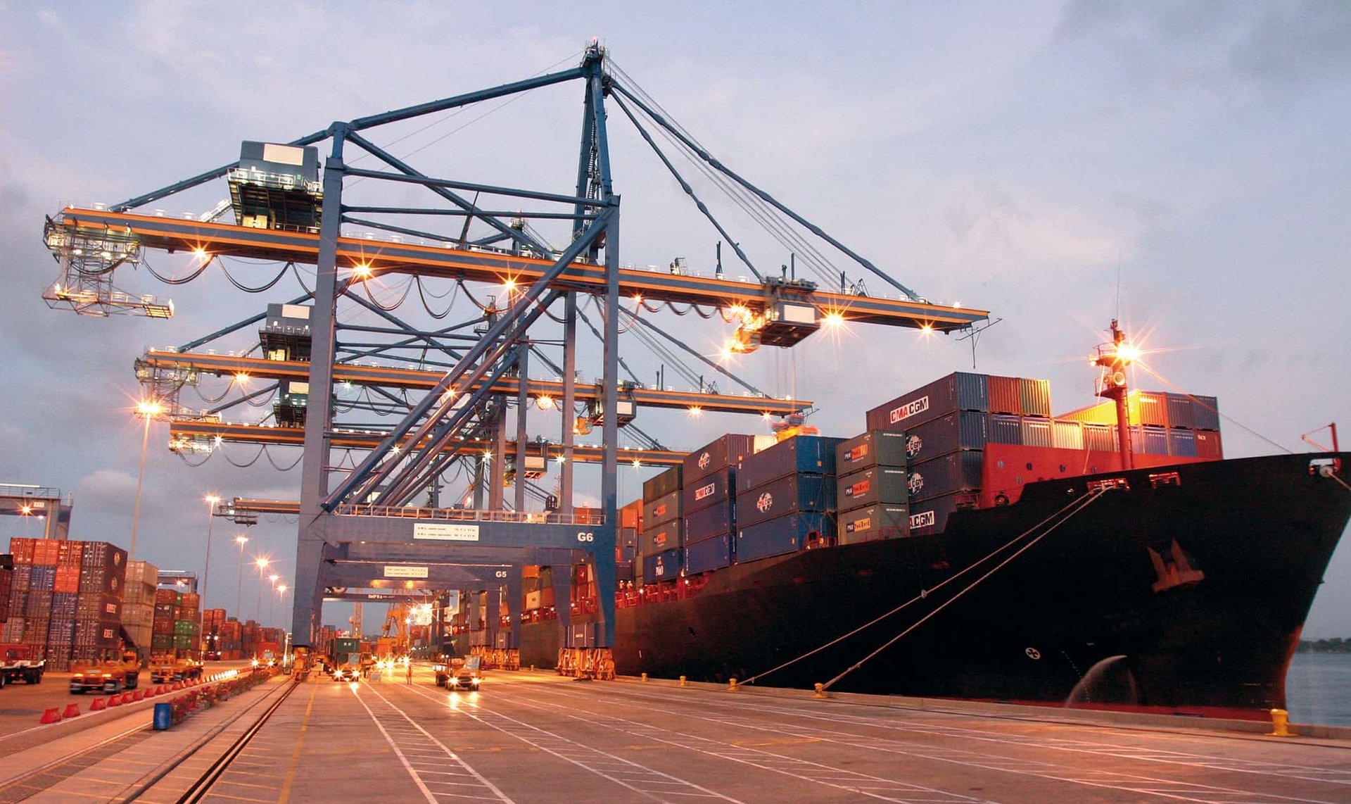
In the demanding world of port operations, continuous-flex cables serve as the lifeline for critical dynamic applications including robotic container handling arms, ship-to-shore (STS) cranes, rubber-tired gantry (RTG) cranes, and automated conveyor systems. These specialized cables must endure millions of flex cycles while maintaining reliable electrical performance in some of the harshest industrial environments on Earth.
Port environments present unique challenges that push cable systems beyond their typical operating parameters. The combination of harsh weather conditions ranging from scorching sun to freezing storms, constant exposure to corrosive salt spray, contamination from hydraulic oils and diesel fumes, and the relentless mechanical movement of heavy machinery creates a perfect storm for cable failure prevention challenges.
Understanding why flexible cables fail in ship-to-shore applications requires examining multiple failure modes that can occur individually or in combination. From electrical continuity loss that can halt crane operations to jacket abrasion that exposes conductors to environmental damage, each failure mechanism has distinct symptoms, underlying causes, and proven prevention strategies. This comprehensive analysis explores the six primary failure modes affecting cable design for high-flex port operations, along with environment-specific stressors that accelerate degradation.
1. Electrical Continuity Loss
Symptoms
The most immediate indication of conductor failure is intermittent or complete signal loss during crane operation. Operators may notice sporadic control responses, flickering lights in control panels, or complete loss of motor function. In sophisticated port automation systems, continuity loss often triggers fault codes and emergency stops, potentially bringing entire terminal operations to a halt.
Causes
Electrical continuity failure in continuous-flex cable systems stems from three primary mechanisms. Improper pitch length configuration during cable construction creates uneven stress distribution across conductor bundles, leading to premature fatigue in individual strands. When the pitch is too tight, conductors experience excessive compression during bending cycles. Conversely, loose pitch configurations allow conductors to migrate and tangle, creating stress concentrations.
Excessive tensile load represents another critical failure mechanism, particularly in long-travel festoon systems common in quay crane applications. When mechanical support systems fail or are inadequately designed, the cable's own weight combined with dynamic loads transfers destructive forces directly to the copper conductors. This situation is exacerbated in port environments where cables may span distances exceeding 100 meters between support points.
Poor conductor design compounds these issues. Solid conductors or those with inadequate strand count cannot accommodate the repeated flexing demands of port applications. The conductor's internal structure must be optimized for flexibility while maintaining current-carrying capacity and mechanical strength.
Port Environment Insights
Cranes with long-travel festoon systems frequently experience conductor overstretching due to inadequate mechanical support design. The challenge intensifies when these systems operate in high-wind conditions common in port environments, where cable sway increases dynamic loading. Additionally, the salt-laden atmosphere accelerates corrosion of exposed conductor strands, weakening their mechanical integrity.
Prevention Strategies
Implementing optimized pitch configurations specific to the application's flex requirements forms the foundation of continuity preservation. Cable manufacturers must calculate pitch length based on bend radius, cycle count, and mechanical loading conditions. Utilizing ultra-flexible conductors constructed from fine-strand copper with appropriate plating ensures maximum flexibility while resisting fatigue.
Proper tension relief systems distribute mechanical loads away from conductors and onto structural support elements. In festoon applications, this includes correctly spaced trolley systems and cable management hardware designed for the specific cable weight and environmental conditions.
2. Insulation Breakdown
Symptoms
Insulation failure manifests through short circuits between conductors or from conductors to ground, triggering protective relays and causing system faults. Advanced monitoring systems may detect decreasing insulation resistance values before catastrophic failure occurs. Visual inspection may reveal cracking, hardening, or discoloration of insulation materials.
Causes
The repetitive mechanical stress of continuous flexing gradually fatigues insulation materials through cyclic deformation. Each bend cycle creates microscopic stress concentrations that accumulate over time, eventually leading to crack initiation and propagation. The situation worsens when cables operate beyond their specified bend radius, concentrating stress in smaller areas.
Internal friction between conductors and insulation compounds the problem. As cables flex, relative movement between components generates heat and abrasion, gradually wearing away insulation thickness. Sharp conductor strands can perforate weakened insulation, creating direct pathways for electrical faults.
Environmental factors unique to port operations accelerate insulation degradation. Ultraviolet radiation from intense sunlight breaks down polymer chains in insulation materials, while temperature cycling from daily heating and cooling creates thermal stress. Chemical exposure from hydraulic fluids, lubricants, and cleaning agents can cause insulation swelling or chemical degradation.
Port Environment Insights
Quay cranes operating with high cycle counts – often exceeding 500,000 cycles annually – accelerate insulation fatigue beyond normal industrial applications. The combination of mechanical stress and environmental exposure creates particularly challenging conditions. Salt deposits can form conductive pathways across insulation surfaces, reducing breakdown voltage and increasing leakage currents.
Prevention Strategies
Selecting high-grade elastomer insulation materials specifically formulated for continuous-flex applications provides superior fatigue resistance compared to standard PVC or PE insulations. These materials maintain flexibility across wide temperature ranges while resisting environmental degradation.
Maintaining correct bend radius throughout the cable installation prevents stress concentration and extends insulation life. Cable support systems must be designed to enforce minimum bend radius requirements even under extreme loading conditions. Implementing comprehensive strain relief at cable terminations distributes mechanical stress over larger areas, reducing localization that leads to insulation failure.
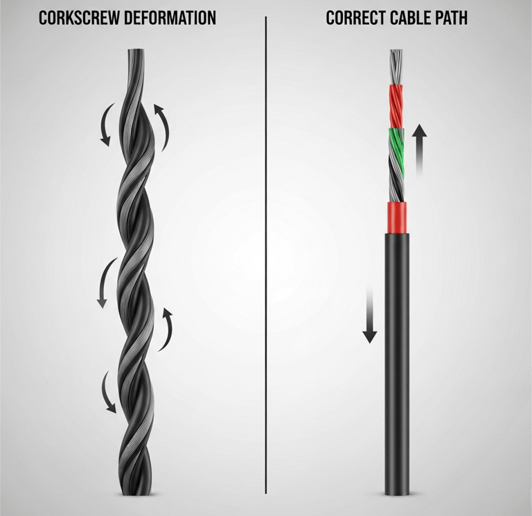

3. Corkscrew Deformation
Symptoms
Corkscrew or "pigtail" deformation appears as helical twisting of the cable along its length, resembling a stretched spring. This deformation often occurs gradually, making early detection challenging. Once established, the twisted configuration becomes permanent and continues to worsen with each flex cycle, eventually leading to conductor breakage or insulation failure.
Causes
Torsional imbalance within the cable construction creates the fundamental conditions for corkscrew deformation. When individual conductor layers or elements have different pitch directions or lengths, flexing motion generates unbalanced torsional forces that accumulate over time. These forces eventually overcome the cable's structural integrity, causing the characteristic helical deformation.
Improper pitch configuration during manufacturing represents a critical factor. Cables constructed with layered rather than bundled configurations are particularly susceptible, as each layer can develop independent torsional forces. Non-optimized pitch relationships between different cable elements create mechanical instability that manifests as progressive twisting.
Port Environment Insights
Motorized reeling systems commonly used in port applications for power and control cable management frequently experience corkscrew deformation. The combination of spooling action and cable tension creates conditions where even minor torsional imbalances can develop into severe deformation. This problem is particularly pronounced in applications where cables must accommodate both linear motion and rotational movement.
Prevention Strategies
Implementing bundled construction techniques eliminates the layer-to-layer torsional imbalances that cause corkscrew deformation. In bundled designs, all conductors are twisted together in a single operation, creating inherent torsional balance. This construction method distributes mechanical forces more evenly throughout the cable cross-section.
Conducting comprehensive torsional testing before installation identifies cables with inherent imbalances that could lead to deformation. These tests simulate operational conditions and can predict long-term behavior under specific application requirements. Cables that fail torsional testing should be rejected before installation to prevent costly field failures.
4. Outer Jacket Abrasion
Symptoms
Visible wear patterns on the cable jacket surface provide the earliest indication of abrasion problems. Initial signs include surface scuffing, color changes, and gradual thinning of the jacket material. Advanced abrasion exposes internal shielding layers or even conductors, creating immediate safety hazards and compromising cable performance.
Causes
Contact with harsh surfaces during normal operation generates the mechanical forces that cause jacket abrasion. Port environments present numerous abrasive surfaces including steel deck plates, concrete surfaces, cable guide rails, and structural steel components. Low-resistance jacket materials cannot withstand repeated contact with these surfaces.
Inadequate wall thickness developed during the extrusion process creates jackets that wear through prematurely. Manufacturing variations can result in thin spots that become failure initiation points. Additionally, some jacket materials become harder and more brittle with age, increasing their susceptibility to abrasion damage.
Port Environment Insights
The practice of dragging cables over steel deck surfaces or allowing them to contact crane rails during operation creates severe abrasion conditions. Port maintenance practices that involve moving cables across rough surfaces during equipment servicing compound the problem. The presence of abrasive particles like sand and salt crystals in the port environment acts like sandpaper on cable surfaces.
Prevention Strategies
Utilizing polyurethane (PUR) jacket materials provides superior abrasion resistance compared to conventional PVC or rubber jackets. PUR materials maintain their properties across wide temperature ranges while offering excellent resistance to oils, chemicals, and mechanical wear. These materials can withstand the harsh conditions typical of port environments while maintaining flexibility.
Ensuring adequate wall thickness through controlled extrusion processes provides the material volume necessary to withstand long-term abrasion. Implementing cable trays, guides, and protective conduits eliminates direct contact between cables and abrasive surfaces. These protection systems should be designed with smooth surfaces and adequate clearances to prevent pinch points or sharp edges that could damage the jacket.
5. Jacket Swelling and Cracking
Symptoms
Jacket swelling appears as visible enlargement of the cable diameter, often accompanied by surface irregularities or bubbling. The swollen jacket may feel soft or spongy compared to unaffected areas. Cracking manifests as visible fissures in the jacket surface that can propagate along the cable length, potentially exposing internal components to environmental contamination.
Causes
Chemical attack from incompatible fluids represents the primary cause of jacket swelling. Hydraulic oils, lubricants, cleaning solvents, and fuel spills can penetrate certain jacket materials, causing them to absorb the fluid and swell. Different polymer materials have varying chemical compatibility, making material selection critical for specific environments.
Temperature extremes create thermal stress that leads to cracking. Rapid temperature changes cause differential expansion and contraction between jacket and internal components, generating stress concentrations. Port environments subject cables to temperature ranges from below freezing during winter nights to over 60°C (140°F) in direct sunlight, creating challenging thermal cycling conditions.
Port Environment Insights
Exposure to hydraulic oil leaks from crane machinery and spills from container handling equipment creates persistent chemical attack conditions. The marine environment adds salt spray exposure, which can accelerate chemical degradation processes. Additionally, cleaning agents used for port maintenance may contain solvents that attack certain jacket materials.
Prevention Strategies
Selecting oil-resistant materials such as thermoplastic polyurethane (TPU) or specialized elastomers provides protection against chemical attack. These materials are formulated to resist swelling and degradation when exposed to oils, fuels, and hydraulic fluids commonly encountered in port environments.
Choosing jackets rated for wide temperature ranges ensures performance across the thermal cycling conditions typical of outdoor port installations. Materials should maintain flexibility at low temperatures while resisting degradation at high temperatures. Regular inspection programs can identify early signs of swelling or cracking before they compromise cable integrity.
6. EMC/Shielding Failures
Symptoms
Electromagnetic interference (EMI) problems manifest as unstable motor performance, erratic control signals, or communication failures in automated systems. Variable frequency drive (VFD) systems may exhibit irregular operation, while sensitive control circuits may experience false triggering or signal corruption. EMI testing often reveals elevated emissions levels exceeding regulatory limits.
Causes
Continuous flexing gradually breaks shield wires through fatigue mechanisms similar to conductor failure. Braided shields are particularly vulnerable, as individual wire strands fatigue and break, reducing overall shielding effectiveness. The problem compounds as broken shield elements can create new sources of electromagnetic emissions.
Poor grounding practices exacerbate shielding problems by failing to provide effective current return paths. Inadequate shield termination techniques or corroded grounding connections compromise the entire shielding system. Additionally, mechanical stress concentrations at cable terminations often cause shield failures at these critical points.
Port Environment Insights
VFD cables in ship-to-shore crane applications are particularly susceptible to shielding failures due to the high-frequency switching currents they carry combined with continuous flexing requirements. The port environment's high electromagnetic noise levels from multiple electrical systems make effective shielding critical for reliable operation.
Prevention Strategies
Implementing double shielding with both braided and foil elements provides redundancy and improved effectiveness. The foil provides high-frequency shielding while the braid handles low-frequency and mechanical requirements. This combination maintains shielding integrity even if individual elements fail.
Proper EMC installation practices including continuous shield bonding, appropriate grounding techniques, and stress relief at terminations ensure long-term shielding effectiveness. Regular EMI testing programs can identify degrading shielding performance before it affects system operation.
7. Specific Port Environment Stressors
Port environments subject cables to unique stressors that accelerate all failure mechanisms. Salt corrosion attacks metallic components including conductors, shields, and hardware, weakening their mechanical properties. Ultraviolet exposure from intense sunlight degrades polymer materials, making them brittle and prone to cracking.
Continuous vibration from heavy machinery operation creates high-frequency stress cycles that contribute to fatigue failures. The massive forces involved in container handling generate shock loads that can exceed cable design parameters. Oil spills and diesel fumes create persistent chemical exposure that attacks jacket materials.
The risk of mechanical impact from containers, spreaders, and steel structures requires robust cable construction and protection systems. These impacts can cause immediate catastrophic failure or initiate damage that leads to eventual failure through other mechanisms.
Conclusion
Understanding common symptoms of continuous-flex cable damage enables proactive maintenance strategies that prevent costly failures in port operations. The six primary failure modes – electrical continuity loss, insulation breakdown, corkscrew deformation, jacket abrasion, jacket swelling and cracking, and EMC/shielding failures – each have distinct symptoms and causes that require specific prevention approaches.
Successful cable failure prevention in port environments requires careful selection of cables designed specifically for high-flex applications, implementation of proper installation techniques, and establishment of regular inspection and maintenance programs. The harsh conditions typical of port operations demand superior materials, robust construction techniques, and proactive maintenance strategies.
Environment-specific material selection, including oil-resistant jackets, corrosion-resistant conductors, and UV-stable polymers, provides the foundation for reliable long-term performance. Proper mechanical design including adequate support systems, protection from physical damage, and maintenance of correct bend radii ensures that cables can withstand the demanding conditions of port operations.
Regular specification reviews and maintenance programs tailored to port environments help identify potential problems before they cause equipment failures. The investment in quality cables and proper maintenance practices pays dividends through improved reliability, reduced downtime, and lower total cost of ownership in critical port operations.
FAQs
Q1: What are the most common reasons for flexible cable failure in port applications?
A: The most common causes include mechanical over-bending, conductor fatigue, jacket abrasion from steel structures, chemical exposure to oils and seawater, and improper cable configuration for high-cycle flexing systems like STS or RTG cranes.
Q2: How can I detect early signs of cable failure in a port crane system?
A: Warning signs include intermittent connectivity, visible jacket wear, cable twisting (corkscrewing), insulation cracking, and increased EMI interference. Regular visual inspection and insulation resistance testing can help detect issues early.
Q3: What type of cable jacket material is best suited for port environments?
A: Polyurethane (PUR) and thermoplastic elastomers (TPE) are highly recommended for their abrasion resistance, oil resistance, and flexibility under harsh environmental conditions common in ports.
Q4: Can continuous-flex cables be used in festoon and reeling systems?
A: Yes, but they must be specifically designed for the application. For festoon systems, flexibility and lightweight design are critical. For motorized reeling systems, torsion resistance, tensile strength, and chemical compatibility are essential.
Q5: How does torsional stress affect cable performance in dynamic port equipment?
A: Torsional stress can lead to corkscrew deformation, conductor breakage, and jacket tearing. Using bundled constructions and cables with proper torsional balancing significantly improves performance.
Q6: Are there standards or certifications required for flexible cables in port machinery?
A: Yes. Cables used in Australian ports should comply with AS/NZS 2802, AS/NZS 5000, and VDE 0250 for durability, electrical safety, and environmental resistance.
Q7: What maintenance practices help prevent continuous-flex cable failure in harsh conditions?
A: Routine inspections, maintaining correct bend radius, using appropriate cable guides/trays, ensuring clean environments around cable paths, and replacing cables showing early wear are all vital for longevity.
Q8: How do I choose the right flexible cable for ship-to-shore crane applications?
A: Look for cables rated for high bending cycles, with oil-resistant jackets, robust shielding (for VFD motors), and temperature tolerance suited to outdoor marine environments. Always consult technical data sheets and application specialists.
Need reliable continuous-flex cables for your port operations? Consult our technical team to find optimized solutions for shipyard, quay crane, and festoon system applications.
How to Reach Us
Get in Touch
SiteMap
Product Catalogue
Festoon Cable
Shore Power Cable


Scan to add us on WeChat