
Why Reeling Cables Fail Prematurely: 10 Causes and Prevention Methods
Why reeling cables fail prematurely: discover the 10 most common causes of reeling cable failure and practical prevention methods to extend service life in cranes, mining, and industrial equipment.
hongjing.Wang@Feichun
7/22/202612 min read
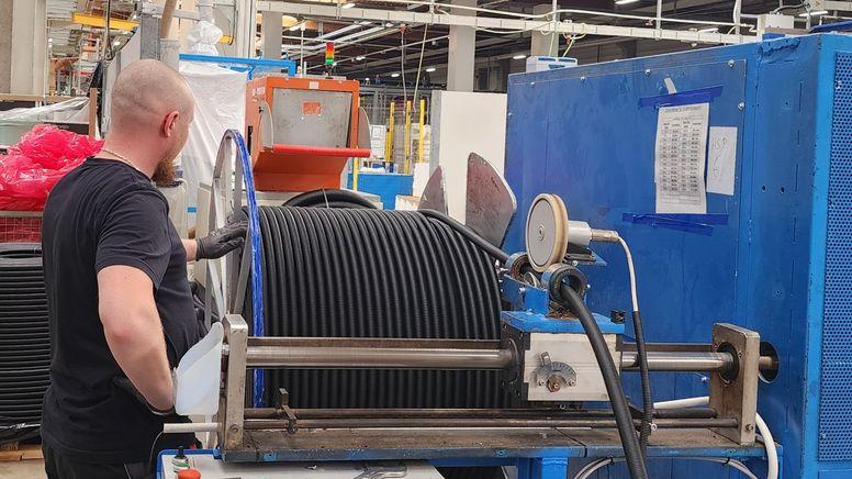
In heavy industrial operations across Australia—from the iron ore mines of the Pilbara and the coal fields of the Bowen Basin to the bustling shipping terminals of Port Fremantle—reeling cables act as the vital lifeline powering heavy mobile machinery. Whether energising a massive dragline, a container-handling quay crane, or an underground continuous miner, these specialised electrical cables are designed to endure dynamic physical movement while transmitting substantial electrical power.
Despite their heavy-duty construction, reeling cables frequently suffer from premature failure. When a cable fails, the costs extend far beyond the price of a replacement reel. Unplanned electrical failures trigger immediate operational downtime, drag down productivity, demand urgent maintenance interventions, and introduce severe safety hazards, including arc flash, electrical shock, and fire.
A common misconception among site managers and maintenance crews is that premature reeling cable failure is simply the result of a manufacturing defect or natural wear and tear. In reality, most early failures are entirely preventable. They stem from a complex interaction between improper cable selection, mechanical abuse, poorly engineered reel geometry, harsh environmental exposure, and reactive maintenance strategies.
Understanding the root mechanisms behind trailing and reeling cable damage allows maintenance teams, plant engineers, and site operators to transition from reactive firefighting to proactive prevention.
What Reeling Cable Failure Looks Like
Detecting cable failure before a catastrophic event occurs requires a trained eye. While some mechanical damage causes immediate power loss, many cable failures begin internally, developing over weeks or months while the outer jacket remains relatively intact.
The visual symptoms of cable degradation usually appear in distinct stages:
External Jacket Damage
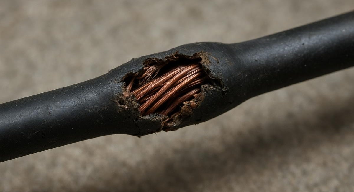
The outermost line of defence is the tough rubber or polyurethane sheath. Early signs of damage include localized abrasion, severe scuffing, deep longitudinal cuts, circumferential tears, and outer jacket splitting. In environments with heavy chemical or heat exposure, the jacket may show signs of blistering, swelling, or thermal cracking.
Internal Conductor and Insulation Damage
When mechanical forces penetrate past the outer jacket, they strain the power conductors, control cores, and insulation layers. Visible symptoms include local bulging, necking (where the cable thins under extreme tension), crushed profiles, or birdcaging—a distinct mechanical deformity where outer strands buckle outward away from the inner core due to torsional stress.
Thermal and Electrical Indications
Under excessive dynamic stress or high electrical loads, internal conductor strands begin to fracture. As individual wire filaments break, the remaining strands must carry the full electrical load, creating localized resistance points. This leads to localized overheating, burning or charring of the outer sheath, melting insulation, and eventually internal short circuits, ground faults, or phase-to-phase arc flashes.
In high-intensity operations like underground mining, mechanical impact often inflicts visible sheath damage and hidden internal strand breakage simultaneously. A cable that looks only slightly scuffed on the outside may actually contain severely fractured conductor strands inside, ready to fail under the next high-current load cycle.
1. Wrong Bending Radius
Every engineered electrical cable possesses a minimum bending radius (MBR)—the tightest curvature around which the cable can be safely bent without damaging its internal components. Violating this radius is one of the primary causes of early cable fatigue and failure.
Static vs. Dynamic Limits
A crucial distinction that site engineers often miss is the difference between a cable’s static bending radius and its dynamic reeling bending radius. A cable installed in a fixed cable tray might require an MBR of 6 to 8 times its overall diameter. However, when that same cable is subjected to continuous reeling, flexing, and directional changes on a crane or shuttle car, its dynamic MBR increases significantly—often requiring 10, 12, or even 15 times the cable diameter depending on the speed and winding configuration.
The Mechanics of Bending Fatigue
When a cable bends around a drum, sheave, or roller, the internal conductors on the outer perimeter of the bend experience tensile stress, stretching them outward. Simultaneously, the conductors on the inner perimeter experience compressive stress.
If the bending radius is too small, these forces exceed the elastic limit of the copper strands and insulation materials. Repeatedly bending a cable tighter than its design limit causes micro-fractures in individual copper wires, rapid work-hardening, and eventual conductor fatigue. Over time, the inner insulation layers crack, allowing moisture ingress or phase-to-phase tracking, which culminates in catastrophic electrical failure.
2. Excessive Tension
Reeling cables are designed to operate under controlled tensile loads, but they are not structural towing ropes. Exceeding maximum tension limits causes severe physical distortion and conductor degradation.
Sources of Tension Overload
Excessive pulling force typically originates from three main operational issues:
Incorrect drum torque settings or faulty reel tensioning systems.
Improper mechanical slack management during travel.
Operational mishaps, such as a mobile machine driving away faster than the cable reel can pay out, or the cable snagging on ground obstacles and pit debris.
Consequences of Tension Failure
Copper is a ductile metal. When subjected to tension beyond its maximum tensile threshold, the copper conductors elongate permanently, reducing their cross-sectional area. A smaller conductor cross-section increases electrical resistance, generating excessive internal heat during normal machine operation.
Sustained tensile stress also stretches the inner insulation layers and protective beddings, causing the internal geometry of the cable to collapse. This cross-sectional deformation leads to core distortion, where power cores twist around one another, leading to premature insulation breakdown and structural core collapse.
3. Incorrect Drum Selection
A reeling cable is only as reliable as the drum system on which it operates. Mismatches between the physical cable and the reeling drum mechanics are a prime source of early cable failure.
Monospire vs. Random/Level Wind Drums
Cable drums generally fall into two categories: single-spiral (monospire) drums and multi-layer random or level-wind drums. Monospire drums lay the cable in a single flat spiral, offering excellent heat dissipation and minimal mechanical crushing. Multi-layer drums store large cable lengths in multiple overlapping layers, which significantly increases mechanical stress on the inner layers.
The Dynamics of Drum Misalignment
Selecting a drum with an incorrect core diameter instantly violates the cable's minimum bending radius. Furthermore, using a drum with improper flange spacing, inadequate drive torque, or inappropriate reel flanges creates severe operational issues:
Crushing and Flattening: On multi-layer drums, excessive tension combined with heavy cable weight forces the upper cable layers to dig directly into the lower layers, flattening the cable's circular profile.
Thermal Trapping: Deeply layered cable reels restrict natural air cooling. If a machine operates under heavy electrical load with many cable layers remaining on the drum, thermal build-up occurs rapidly, degrading the primary core insulation.
Layering Stress: Poor drum geometry causes the cable to cross over unpredictably during winding, creating extreme point-load pressure spots that break conductors and slice through outer jackets.
4. Poor Cable Guidance
Routing a cable from a moving machine to a fixed power point requires well-designed guidance hardware. Poorly aligned rollers, damaged sheaves, and misaligned cable guides introduce harmful mechanical forces.
The Dangers of Side-Loading and Shearing
Guidance systems must align smoothly with the cable’s natural path of movement. When guide rollers are misaligned, frozen due to bearing failure, or fitted with sharp edges, the cable is subjected to severe side-loading and lateral shear stress.
Instead of rolling smoothly over a guide, the cable is pulled sideways across static metal surfaces. This creates continuous abrasion that rapidly wears away the outer protective sheath.
Sinuous Path Friction
Forcing a cable through complex, tightly staggered roller pathways increases bending cycles exponentially. Every time a cable passes over a guide roller, it undergoes a complete flex cycle. If an operator installs multiple small guide sheaves to negotiate structural obstacles on a machine, the cumulative mechanical fatigue on the copper conductors is multiplied, drastically cutting the cable's expected lifespan.
5. Over-Speed Operation
Modern industrial equipment operates at increasingly high travel speeds to maximize productivity. However, operating cable reeling systems at speeds exceeding their design thresholds leads to rapid mechanical and thermal degradation.
Dynamic Impact Forces
As operational speeds increase, the dynamic forces acting on the cable during pay-out and pay-in skyrocket. Sudden machine acceleration or deceleration creates massive shock loads. When a high-speed gantry crane or shuttle car changes direction rapidly, the cable experiences severe tension spikes that snap conductor strands and damage reel drive mechanisms.
Kinetic Heat and Abrasion
High-speed reeling dramatically increases kinetic friction as the cable passes through guide rollers, over dynamic sheaves, and onto the drum. Friction generates localized heat on the outer sheath, softening protective rubber compounds and making them far more vulnerable to slicing and abrasion. Furthermore, high payout speeds increase the likelihood of cable whipping, where the cable bounces violently off structural steelwork or rough terrain.
6. Mechanical Impact and Abuse
In harsh physical environments like surface mining, quarries, and construction sites, direct mechanical impact is the single leading cause of physical cable destruction.
Physical Hazards on the Worksite
Mobile equipment operating in close quarters creates constant mechanical hazards for trailing and reeling cables:
Crushing: Heavy haul trucks, loaders, and auxiliary service vehicles driving directly over unprotected cables.
Puncture and Slicing: Jagged, freshly blasted rock falling from excavator buckets directly onto trailing lines, or cables being dragged over sharp pit walls and steel grating.
Squeezing: Cables getting pinched between moving machinery components or crushed against fixed structural posts.
Surface Mining Realities
In heavy surface mining applications involving massive draglines and electric shovels, cables are routinely dragged over abrasive, rocky ground for hundreds of metres. This continuous dragging strips away outer sheath material, exposing inner steel reinforcement braids or copper shields to environmental moisture and physical tearing. Once the outer protective boundary is breached, water ingress quickly degrades the primary insulation, triggering short-circuit earth faults.
7. Extreme Temperature Exposure
Environmental ambient temperatures and operational heat play a massive role in governing cable longevity. Operating outside a cable’s engineered thermal window leads to rapid material failure.
Cold Weather Vulnerabilities
In freezing conditions, standard rubber and thermoplastic jacket compounds lose their natural flexibility and turn brittle. If a frozen cable is forced to reel, flex, or bend around a drum, the outer jacket will crack circumferentially right down to the inner cores. This allows moisture and atmospheric contaminants direct access to the live electrical conductors.
High Heat Degradation
Conversely, extreme heat—whether from high ambient summer temperatures in Australia's desert regions, direct exposure to unshielded sunlight, radiant heat from hot engine compartments, or internal electrical resistance—accelerates chemical degradation.
Excessive thermal exposure softens outer sheaths, drastically reducing their tear and abrasion resistance. Internally, sustained elevated temperatures accelerate the thermal aging of primary insulation materials like ethylene propylene rubber (EPR) or cross-linked polyethylene (XLPE), causing them to harden, become brittle, and lose their dielectric strength over time.
8. Chemical Contamination and Environmental Attack
Industrial sites are rarely clean environments. Reeling cables operating on heavy machinery are continuously exposed to aggressive chemical agents that attack polymeric compounds.
Common Chemical Contaminants
Cables installed on mobile mining equipment, ship-to-shore cranes, and heavy transport machinery frequently come into contact with:
Diesel fuel and petrol.
Hydraulic oils and lubricating greases.
Solvents, cleaning agents, and degreasers.
Saline coastal air and acidic mine washwater.
Degradation Mechanisms
When non-chemically resistant rubber or thermoplastic sheaths are exposed to oils and fuels, hydrocarbon molecules penetrate the polymer matrix. This causes swelling, softening, and loss of tensile strength in the outer sheath.
Over time, the contaminated sheath loses its physical toughness, becoming sticky, gummy, and highly susceptible to peeling or tearing under minimal abrasion. If chemical fluids manage to penetrate the outer jacket, they degrade internal bedding compounds and core insulation, creating conductive paths for current leakage and short circuits.
9. Incorrect Cable Specification
One of the most frequent root causes of premature failure occurs long before the cable is ever powered up: selecting the wrong type of cable for the application.
Flexible Cable vs. True Reeling Cable
A widespread mistake made during procurement is assuming that any heavy-duty flexible rubber cable (such as standard Class 5 or Class 6 flexible power cables) is suitable for dynamic reeling duty.
Standard flexible cables are engineered for occasional flexing, manual relocation, or semi-static installation. They lack the specialized internal construction required for continuous high-tension reeling.
FeatureStandard Flexible CableDedicated Engineered Reeling CablePrimary Design IntentOccasional flexing, manual relocation, static connectionsContinuous dynamic reeling, high tensile loads, high speedsTorsional ResistanceLow to moderate; susceptible to core twistingHigh; built with integrated anti-torsion braid matrixSheath ToughnessStandard abrasion resistanceHeavy-duty, high-grade polyurethane or special rubber compoundInternal Lay LengthLonger lay length optimized for flexibilityShort, tightly controlled lay lengths to resist mechanical strainCore ReinforcementMinimal to noneHigh-tensile aramid center strain relief member
The Hidden Danger of Torsional Stress
True reeling cables feature specialized design elements, such as short lay-length core twisting, high-tensile aramid center strain members (Kevlar cores), and embedded polyester or textile anti-torsion braids integrated into the outer sheath.
If a standard flexible cable is installed on a reeling drum, the continuous unwinding and rewinding forces rapidly induce torsional stress. Without internal anti-torsion reinforcement, the internal conductors twist around each other, causing the cable to kink, form birdcage deformities, and fail prematurely.
10. Inadequate Maintenance and Poor Inspection Practices
Even the highest-grade, perfectly specified reeling cable will fail prematurely if subjected to neglect and reactive maintenance practices.
Missing Early Warning Signs
Operational environments often treat trailing and reeling cables as basic consumables rather than critical electrical assets. Inspections are frequently overlooked until a machine shuts down due to a blown earth-leakage relay or major mechanical damage.
Without regular, structured visual and electrical inspections, minor issues quickly escalate:
A tiny surface nick in the jacket goes unnoticed, allowing water ingress that corrodes the braided copper shield.
A misaligned roller guide continues to scrape the cable sheath in the exact same spot until the inner conductors are exposed.
Accumulation of debris, dirt, and dried mud on the reel drum goes uncleaned, changing the drum profile and causing localized cable crushing.
Lack of Failure Investigation
When a cable fails, maintenance teams often perform a quick inline splice or simply swap out the damaged section without investigating why the failure happened. If the underlying cause—such as excessive reel tension, a frozen guide roller, or chemical contamination—is left unaddressed, the newly installed cable will suffer the exact same fate in short order.

Comprehensive Prevention Methods: How to Extend Reeling Cable Life
Maximising the service life of reeling cables requires a holistic, system-level strategy. The cable, the reeling drum, the guide system, and the operating environment must be engineered and maintained as a unified power transmission system.
1. Optimize Cable Selection and System Design
Match Specifications to Application: Always select cables specifically rated for dynamic reeling service, ensuring the voltage rating, current-carrying capacity, mechanical tensile rating, and chemical resistance match actual site conditions.
Integrate Central Strain Relief: For high-tension or deep vertical reeling applications, specify cables constructed with an integrated high-tensile aramid fiber center core to absorb pulling forces.
Ensure Anti-Torsion Protection: Verify that the cable construction includes an anti-torsion braid (such as an embedded polyester mesh) integrated between the inner and outer sheaths to counteract twisting forces.
2. Standardize Mechanical and Physical Controls
Enforce Bending Radius Rules: Verify that all reeling drums, deflection sheaves, guide rollers, and payout funnels comply strictly with the cable manufacturer’s dynamic minimum bending radius.
Calibrate Reel Tension: Regularly check and calibrate the torque and tension settings on cable drum drives. Ensure tension stays well within the allowable continuous pulling force of the cable.
Install Smooth Guidance Systems: Utilize wide, large-diameter, smooth-running guide rollers fitted with sealed, low-friction bearings. Avoid sharp turns or convoluted routing paths.
3. Implement Strict Operational Practices
Enforce Speed Controls: Keep equipment travel and reeling payout speeds within engineered limits to avoid shock loads, dynamic whipping, and thermal overload.
Maintain Clean Cable Pathways: Keep roadways, pit floors, and travel paths clear of sharp rocks, debris, standing water, and chemical spills.
Use Protective Crossover Ramps: Where vehicles must cross cable paths, install heavy-duty rubber cable crossover bridges or construct dedicated overhead gantries to protect cables from vehicle traffic.
4. Establish a Proactive Maintenance and Inspection Regime
Conduct Daily Visual Checks: Train equipment operators and maintenance technicians to inspect cables daily for jacket cuts, crushing, bulging, unusual wear patterns, and uneven winding.
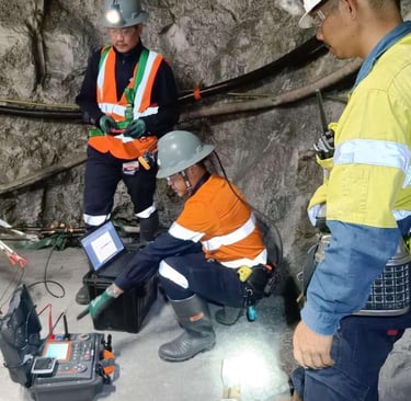
Perform Periodic Electrical Testing: Schedule regular insulation resistance (IR) testing, conductor resistance checks, and earth-continuity testing to detect internal conductor strand breakage before catastrophic failure occurs.
Clean and Align Regularly: Keep reeling drums and guide rollers clean of built-up mud, grease, and debris. Inspect roller bearings regularly to prevent frozen guides from scraping the cable sheath.
Perform Thorough Root-Cause Analysis: Whenever a cable suffers mechanical or electrical damage, conduct a formal failure investigation to identify and correct the underlying system issue before replacing the cable.
Case Evidence and Industry Realities
The physical mechanisms behind reeling and trailing cable failures are demonstrated repeatedly across field reports and formal industry incident investigations.
Mining Operations: Mechanical Insult Data
Official safety data published by Resources Safety & Health Queensland (RSHQ) highlights the extent of mechanical damage in heavy industrial settings. Over a three-year reporting period, Queensland mines documented 304 individual trailing cable damage incidents caused directly by mechanical insult.
The primary sources of damage included interactions with:
Shuttle cars and underground continuous miners.
Surface draglines and electric shovels.
Heavy haul trucks and mobile support equipment.
RSHQ safety alerts repeatedly point out high-voltage trailing cable damage in dragline and shovel operations, confirming that poor cable handling, inadequate cable crossover protection, and mechanical impact remain top operational hazards in surface and underground mining.
Offshore and Industrial Analogs: Corrosion and Fatigue
While electrical reeling cables and steel wire ropes serve different functional purposes, their mechanical failure modes—fatigue, bending stress, improper guidance, and neglected inspection—are identical.
A notable safety study reviewed by the International Marine Contractors Association (IMCA) and marine safety boards detailed an offshore cargo vessel incident where a crane's wire rope snapped without warning, causing a 69-tonne heavy lift load to plunge to the deck. The incident resulted in millions of dollars in mechanical destruction and severe operational disruption.
The investigation revealed that while the outer surface appeared operational, internal metal fatigue, hidden corrosion, and localized structural stress—compounded by missed inspection cycles—caused the core to fail from within. This incident serves as a striking industrial analog for electrical reeling cables: internal dynamic degradation often occurs silently long before visual symptoms trigger alarm.
User-Level Discussions from the Field
Field operators and site mechanics frequently share real-world troubleshooting experiences regarding dynamic cable and wire rope wear. In an active forum discussion on https://www.heavyequipmentforums.com/threads/wire-rope-damage.97163/, equipment operators and field technicians discuss recurring mechanical damage patterns seen across heavy machinery.
Participants share observations on how minor alignment mistakes on sheaves, subtle drum cross-over binding, and unrecognized point-load crushing create severe, localized structural failure. The consensus among field professionals mirrors engineering theory: unexplained mechanical damage on reeling lines is almost always traceable back to physical abuse, worn guidance hardware, or incorrect equipment setup rather than a failure of the material itself.
Conclusion
Premature reeling cable failure is rarely an unavoidable mystery or a simple material flaw. Instead, it is almost always the predictable outcome of mechanical stress, improper reel geometry, operational abuse, or reactive maintenance practices.
Whether managing a fleet of container cranes at a marine terminal or operating heavy electric draglines in a surface mine, preventing early cable failure requires a complete system-wide approach. By selecting the right cable for dynamic reeling duty, engineering smooth drum and guidance mechanics, protecting cables from physical impact, and conducting regular proactive inspections, site operators can dramatically reduce unplanned downtime, cut operating costs, and maintain a safer workplace.
How to Reach Us
Get in Touch
SiteMap
Product Catalogue
Festoon Cable
Shore Power Cable




Scan to add us on WeChat