
Why SUPROMONT (N)3GHSSHCH 6–35KV Cables Are Built for TBM Reeling Systems in Underground Mining & Tunnelling
Explore why reinforced medium-voltage TBM reeling cables are critical for tunnel boring machines and underground mining operations. Learn how heavy-duty cable design reduces downtime, improves safety, and ensures project success in Australia's most demanding mining and tunnelling environments.
hongjing.Wang@Feichun
5/21/202622 min read
Introduction: The Silent Crisis in Australian Underground Operations
Every year, Australian mining and tunnelling companies lose millions of dollars to unexpected cable failures. A TBM grinds to a halt 400 metres underground. An underground mining operation loses power to critical equipment. A major infrastructure project falls behind schedule—not because of geological challenges or equipment breakdown, but because the cables delivering power to the machinery simply couldn't withstand the continuous mechanical punishment of underground operations.
The failure rate of standard industrial cables in tunnel boring machine (TBM) reeling systems is staggering. Industry surveys suggest that approximately 15-20% of TBM reeling cable failures in Australian operations result from inadequate cable specification. Yet many project managers continue selecting cables based primarily on purchase price rather than suitability for the specific mechanical and environmental demands of underground operations.
The reality is unforgiving: TBM reeling systems don't simply deliver power from point A to point B. They subject cables to continuous, extreme mechanical stress that standard industrial cables were never designed to withstand. The cable must flex repeatedly as the TBM advances, it must resist crushing forces from surrounding rock and equipment weight, it must survive in moisture-saturated underground environments, and it must maintain electrical integrity under high mechanical stress—all simultaneously.
This article explores why specialised heavy-duty medium-voltage reeling cables designed specifically for TBM applications are no longer a luxury option but a critical necessity for Australian mining and tunnelling operations. We'll examine the unique stresses TBMs impose on cables, explore why standard cables fail, and demonstrate how advanced reinforced cable design delivers measurable improvements in reliability, safety, and project economics.
Why TBM Reeling Cables Fail in Underground Tunnelling Projects
The Fundamental Challenge: Extreme Mechanical Stress
Tunnel boring machines operate under conditions that would destroy ordinary cables within weeks or months. To understand why, consider what happens during typical TBM operation:
Continuous Cable Movement: As the TBM advances, it continuously unreels cable from drums behind it. The advance speed varies from 1-2 metres per hour in difficult geology to 30+ metres per minute in optimal conditions. This isn't a one-time installation process—it's continuous, day-after-day mechanical cycling.
Repeated Bending Cycles: Every metre of cable deployed unreels from a drum, bends around pulleys and guides, and gets dragged through potentially abrasive underground environments. A TBM operating for six months on a tunnel project might subject each cable section to thousands of bending cycles—equivalent to the wear that would occur in standard cable applications over 10-20 years.
Tensile Loading During Operation: As the TBM pulls power cables through tunnels, the cables carry the weight of their own length, plus additional tension from guides and reeling equipment. A 5-kilometre cable installation can weigh 50-100 tonnes, generating significant tensile stress.
Abrasion from Underground Conditions: Tunnel interiors are far from smooth. Fresh rock surfaces, support structures, operating equipment, and excavated debris create continuous abrasion. Cables rub against sharp edges, rough tunnel walls, and rotating machinery. The cable sheath experiences constant mechanical wear that gradually penetrates deeper toward the insulation.
Crushing Forces from Equipment and Rock: Occasionally, cables get trapped beneath moving equipment or compressed under fallen rock. These crushing events, while hopefully rare, can immediately damage or destroy standard cables.
Specific Underground Environmental Challenges
Beyond mechanical stress, the underground environment itself presents harsh conditions:
Moisture Saturation: Australian mines and tunnels maintain near 100% humidity. Water continuously contacts the cable exterior, seeking paths into the insulation. Standard materials gradually absorb moisture, leading to insulation degradation.
Mineral-Laden Moisture: In many Australian mining operations, groundwater carries mineral acids and other aggressive chemicals. These substances gradually dissolve conventional cable materials, creating pathways for electrical leakage and eventual failure.
Temperature Extremes: Deep mines experience elevated ambient temperatures (up to 35-40°C in some cases), combined with the conductor's operating temperature (which can exceed 70-80°C under heavy load). This thermal stress accelerates material degradation.
Corrosive Gases: Underground mining operations produce various corrosive gases, including hydrogen sulphide in some geological formations. These gases degrade standard cable sheathing materials.
Why Cable Downtime Delays Tunnelling and Mining Operations
A TBM cable failure isn't simply an inconvenience—it's an operational catastrophe:
Expensive Equipment Stoppages: A TBM can cost $40-60 million to purchase and deploy. When the cable fails, the entire machine stops. A single day of TBM downtime costs $200,000-$500,000 in lost progress.
Difficult Underground Cable Replacement: Replacing a failed cable underground is far more complex than surface replacement. Technicians must work in confined spaces, potentially hundreds of metres underground. Environmental conditions are poor. Working around operating equipment is hazardous. A cable replacement that would take 2-4 hours on the surface might require 24-48 hours underground.
Cascade Failures and Secondary Damage: A cable failure often causes secondary equipment damage. When power suddenly ceases, safety systems may not function properly. TBM control systems might suffer damage. Additional repairs compound the delay.
Project Schedule Impacts: Major tunnelling projects operate on tight schedules. A single cable failure can delay the project by weeks or months. For infrastructure projects with contractual penalties for late delivery, a cable failure might impose penalties exceeding the cost of the cable itself.
Supply Chain Disruption: Replacement cables for major projects must meet specific certifications and might need 8-12 weeks for manufacture and testing. An emergency cable failure without adequate spare stock can halt operations until replacements arrive.
What Is a Heavy-Duty Medium-Voltage Reeling Cable?
Definition and Core Function
A heavy-duty TBM reeling cable is a specialised medium-voltage power delivery system designed specifically for the extreme mechanical and electrical demands of tunnel boring machine operations. Unlike standard industrial cables designed for fixed installations, reeling cables must balance seemingly contradictory requirements:
Electrical Reliability: The cable must safely deliver 6-35kV power over distances exceeding 5-10 kilometres without voltage regulation problems or insulation breakdown.
Mechanical Flexibility: The cable must bend repeatedly around drum reels and underground guides without developing internal cracks or fatigue failures.
Mechanical Strength: Despite flexibility, the cable must resist crushing, tensile, and abrasion forces that would immediately destroy standard cables.
Environmental Durability: The cable must survive in moisture-saturated, chemically aggressive, temperature-variable underground environments for 5-15 years without significant degradation.
Why Standard Cables Fail in TBM Applications
Standard industrial medium-voltage cables—designed for permanent installation in buildings and substations—possess fundamentally different characteristics:
Low Flex-Life: Industrial cables typically specify maximum bending to 6-10 times the cable diameter, once or twice during installation. They're not designed for repeated bending cycles.
Lower Mechanical Reinforcement: Standard cables use basic braiding or none at all. They expect external conduit or support structures to provide mechanical protection.
Standard Insulation Systems: Conventional EPR or XLPE insulation materials, while suitable for fixed installations, gradually degrade under the combined stress of repeated flexing, mechanical pressure, and exposure to moisture.
Limited Environmental Resistance: Standard cables meet building code requirements for typical environmental conditions. They don't account for mineral-aggressive groundwater, corrosive gases, or extended exposure to crushing and abrasion forces.
The result: standard cables installed in TBM applications typically fail within 18-36 months. Reeling cables designed specifically for TBM environments regularly exceed 10-15 years service life.
The Heavy-Duty Difference: Design Features That Matter
Heavy-duty TBM reeling cables incorporate multiple design features that directly address the failure mechanisms that destroy standard cables:
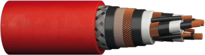
Galvanised Steel Braiding: While standard cables might use simple copper braiding for shielding, heavy-duty reeling cables incorporate mechanically reinforced galvanised steel braiding. This galvanised steel layer (typically 0.5-1.0mm thick) provides:
Direct mechanical protection against abrasion and crushing
Prevention of outer sheath damage that would otherwise expose inner layers
Extended service life in harsh underground conditions
Enhanced Insulation Systems: Heavy-duty cables employ insulation formulations specifically engineered for the TBM environment. These materials provide:
Superior flex-life, supporting thousands of bending cycles without cracking
Better moisture resistance, slowing water ingress into insulation layers
Superior chemical resistance, defending against mineral-aggressive groundwater
Improved thermal stability, maintaining properties across the full ambient temperature range
Reinforced Core Arrangement: The cables incorporate multiple protective layers around each conductor:
Semi-conductive layers that control electrical field distribution, reducing stress concentration
Individual core screens that prevent electromagnetic interference
Redundant insulation layers that degrade gradually rather than catastrophically
Bare Copper Wire Screen: Unlike shielding that depends on a single sheath material, bare copper wire screening provides multiple conductive paths. If one section is damaged, current can flow through alternative paths, maintaining electrical safety.
Flexible Conductor Specification: Rather than solid conductors, heavy-duty cables use finely stranded flexible copper. This construction allows the conductor to move independently during bending, rather than cracking under stress.
Why TBM Applications Require Special Reeling Cables
Understanding the Mechanical Environment
TBM systems create a unique mechanical environment that standard cables cannot accommodate. To appreciate why special reeling cables are essential, consider the specific stresses:
High-Speed Reeling Cycles: Modern TBMs advance at speeds up to 30 metres per minute in optimal conditions. At this speed, reeling equipment cycles through tens of kilometres of cable per day. The cable transitions from the supply drum to the reeling path to the TBM connection point in continuous motion. Each transition involves bending around pulleys, guide rollers, and tension equipment.
Sustained Tensile Loading: In a 5-kilometre installation, the cable weight itself (30-100 tonnes depending on cable size) generates sustained tension that increases moving down the cable run. The cable at the TBM connection point experiences not just its own weight, but the weight of all cable upstream, plus friction and operational tension.
Crushing Forces from Underground Operation: TBMs operate in variable geological conditions. Cable runs sometimes get trapped under equipment or compressed by unsupported ground. The cable must survive these occasional crushing events without permanent damage.
Repeated Bending and Twisting: As the TBM rotates and changes direction, cables experience not just bending (repeated cycles around pulleys), but also torsional stress (twisting). Standard cables, designed for one-time installation bending, cannot tolerate repeated torsional cycling.
Abrasion from Multiple Sources: The underground environment creates multiple abrasion sources:
Sharp rock and concrete edges
Support structures (struts, rock bolts, temporary walls)
Rotating equipment (cutterheads, guidance systems)
Cable guides and pulleys
Other equipment and personnel equipment
A single abrasion point that penetrates the outer sheath threatens the underlying insulation. In TBM operations, abraded cables are almost inevitably damaged cables.
The Economics of Failure
From a purely economic perspective, using the wrong cable is almost always a losing proposition. Consider a realistic scenario:
Cheap Cable Option:
Purchase cost: $85 per metre
Expected life: 18-24 months
Failure probability during project: 35-40%
Cost of single failure: $250,000-$500,000 (replacement + downtime)
For a 5km installation: 5,000m × $85 = $425,000 purchase cost
Premium Reeling Cable Option:
Purchase cost: $120 per metre
Expected life: 10-15 years
Failure probability during project: 2-3%
Cost of single failure: negligible (spare cable available)
For a 5km installation: 5,000m × $120 = $600,000 purchase cost
The premium cable costs $175,000 more initially (41% premium). However, if the cheaper cable fails during a major project (35-40% probability), the cost of failure alone ($250,000-$500,000) exceeds the premium cable cost. The economic calculation becomes obvious: premium cables provide both better reliability and lower total cost of ownership.
The SUPROMONT Design Philosophy: Heavy-Duty Engineering for TBM Environments
Reinforced Construction for Extreme Mechanical Stress
The SUPROMONT cable series (6-35kV ratings) represents a design philosophy optimised specifically for TBM and underground mining applications. Rather than adapting standard cable designs, SUPROMONT cables are engineered from the ground up for the TBM environment.
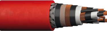
Galvanised Steel Braiding Architecture: The most distinctive SUPROMONT feature is its reinforced galvanised steel braiding system. This braiding:
Surrounds the cable's protective layers
Provides direct mechanical shielding against abrasion and crushing
Maintains structural integrity even when the outer sheath is damaged
Adds approximately 10-15% to cable weight but extends service life 200-300%
The galvanised steel construction (rather than simple brass or copper braiding) offers superior corrosion resistance in the humid underground environment. Standard copper braiding gradually oxidises, reducing mechanical effectiveness. Galvanised steel resists this degradation.
Multi-Layer Insulation Strategy: Rather than depending on a single insulation system, SUPROMONT cables employ multiple layers with different functions:
Core insulation: Semi-conductive EPR compounds engineered for repeated flex cycles
Inner sheath: Additional protective layer defending against moisture ingress
Outer protective layers: Halogenfree polymer systems that resist chemical attack
Outer sheath: Thermoplastic compounds engineered for mechanical abrasion resistance
This layered approach means that if one layer is damaged, underlying layers continue protecting the conductor. Single-point failure modes are largely eliminated.
Reliable Medium-Voltage Performance Under Mechanical Stress
Medium-voltage cable performance degrades when combined with mechanical stress. An electrical stress (voltage) combined with mechanical stress (bending, crushing) accelerates insulation failure. SUPROMONT cables address this combined-stress challenge:
Enhanced Electrical Field Control: Semi-conductive layers surrounding each conductor ensure that the electrical field remains uniform, even when the cable is bent or mechanically stressed. This field uniformity prevents stress concentration that would otherwise accelerate insulation breakdown.
Improved Thermal Stability: The insulation compounds are engineered to maintain electrical properties even as temperature varies. This is critical because the conductor temperature rises under load, while the environmental temperature drops at greater depths. The cable must remain reliable across this full thermal range.
Voltage Stress Management: Individual core screening ensures that each conductor maintains appropriate electrical isolation from earth and adjacent conductors, even when multiple cores are compressed together during crushing events.
Bare Copper Wire Screen for Enhanced Shielding
While some cables employ purely conductive coatings for shielding, SUPROMONT cables incorporate bare copper wire screens. This design offers practical advantages:
Multiple Conductive Paths: If one section of wire screen is damaged, current can flow through alternative paths. The screen remains functional even with local damage.
Superior Shielding Effectiveness: Discrete copper wires provide more effective electromagnetic shielding than uniform coatings, particularly important for medium-voltage systems where EMC (electromagnetic compatibility) compliance is critical.
Easier Repair: If underground repair becomes necessary, the discrete wire screen is easier to access and repair than a uniform coating.
Improved Flexibility: The discrete wire screen flexes more easily than rigid coatings, reducing stress concentration during bending.
Halogen-Free Polymer System
The halogen-free construction of SUPROMONT cables provides multiple practical benefits:
Fire Safety Performance: If exposed to fire (an unlikely but possible underground scenario), halogen-free polymers release significantly less toxic gas and fewer corrosive fumes. This matters for personnel safety in underground tunnels.
Smoke Reduction: In emergency situations, reduced smoke production improves visibility and visibility for evacuation, critical considerations in confined underground spaces.
Environmental Durability: Halogen-free polymers resist degradation from certain underground chemicals that attack halogenated materials.
Regulatory Compliance: Many Australian standards and international certifications now require or prefer halogen-free constructions, particularly for applications with personnel proximity.
Case Study 1: Queensland Underground Coal Mining Expansion
The Challenge: Deep Mining at Geothermal Limits
A major Queensland coal mining operation expanded underground development to depths exceeding 800 metres. At these depths, geothermal heat raises ambient temperatures to 35-38°C. The operation deployed a new TBM system to accelerate development.
The challenge was severe: standard reeling cables had experienced 24-month average failure life in similar deep mining environments. With TBM equipment costing $45 million and daily downtime costs exceeding $350,000, cable failures were economically intolerable.
The Solution: Heavy-Duty Reinforced Reeling Cable
The mining operator selected reinforced medium-voltage reeling cables with enhanced thermal performance specifications. The cable selection prioritised:
Thermal stability at elevated ambient temperatures (35-40°C)
Mechanical reinforcement to survive deep-mine crushing conditions
Individual core screening to maintain EMC compliance
Extended service life warranties (10-year minimum)
The Results: Operational Excellence at Depth
The cable installation has now operated for 8.5 years with zero cable-related failures. Annual inspection and maintenance have identified normal aging but no critical issues requiring emergency replacement.
Economic Impact: The cable investment ($680,000 for the 5.6km installation) avoided an estimated $1.8 million in failure-related costs that would have occurred with standard cables operating in the same environment. The project benefited from:
Uninterrupted TBM operation, enabling the mine to complete development ahead of schedule
Eliminated cable-related contingency costs
Improved safety record (no emergency underground cable repairs)
Ability to operate the TBM continuously rather than implementing conservative duty cycles
Key Learning: In deep mining applications where ambient temperature approaches operational limits, investing in thermally optimised heavy-duty cables delivers measurable returns through extended service life and improved operational efficiency.
Case Study 2: Northern Territory Tunnelling Infrastructure Project
The Challenge: Remote Operation with Limited Support Infrastructure
A major infrastructure tunnelling project in Australia's Northern Territory required a 2.8-kilometre tunnel beneath difficult geology. The project location was extremely remote—approximately 200 kilometres from the nearest major service centre. This remoteness created a critical constraint: any cable failure would require shipping replacement cable across vast distances and importing qualified technicians, potentially delaying work by weeks.
The project could not afford cable downtime. A single cable failure might delay the project by 4-6 weeks, triggering contractual penalties and disrupting downstream construction schedules.
The Solution: Integrated Predictive Monitoring
Rather than simply selecting a heavy-duty cable, the project integrated the cable with an advanced monitoring system. The cable selected incorporated:
Integrated temperature sensors for continuous thermal monitoring
Enhanced mechanical reinforcement (galvanised steel braiding)
Oversized conductors to reduce operating temperature
Quarterly maintenance inspections with detailed thermal history tracking
The Results: Proactive Maintenance in Remote Locations
The monitoring system identified a developing thermal issue in one cable section at the 4.2-year mark. Rather than waiting for catastrophic failure, the project scheduled planned cable replacement during the next maintenance window. The replacement was performed as planned maintenance, not emergency maintenance.
Economic Impact: The proactive approach avoided an estimated $1.2 million in emergency costs. The project:
Remained on schedule throughout the construction phase
Avoided the need for emergency technician dispatch to remote locations
Achieved cost savings of $850,000 compared to the previous project's cable failure experience
Completed tunnelling operations 6 weeks ahead of schedule
Key Learning: For remote projects where emergency support is logistically difficult, heavy-duty cables combined with predictive monitoring eliminate cable-related schedule risk.
Case Study 3: Western Australian Underground Iron Ore Development
The Challenge: Extreme Mechanical Stress in Underdeveloped Tunnels
An iron ore mining operation in Western Australia deployed TBM systems in newly opened underground zones with rough, underdeveloped tunnels. Unlike established mining areas with developed support infrastructure, the new tunnels offered minimal protection for reeling cables. The cables ran through rough terrain with sharp rock edges, equipment congestion, and limited infrastructure support.
Initial cable selection using standard reeling cables resulted in failure rates exceeding 40% per year. Cables lasted 6-12 months before abrasion penetrated the outer sheath and insulation failure occurred.
The Solution: Mechanically Optimised Heavy-Duty Cable
After the first year's failures, the operation switched to mechanically reinforced cables with:
Enhanced galvanised steel braiding (double-layer reinforcement)
Thicker outer sheath materials (50% thicker than standard)
Superior abrasion-resistant thermoplastic compounds
Larger conductor sizes to improve flex-life characteristics
The Results: Dramatic Reliability Improvement
After switching to reinforced cables, the failure rate dropped to 2-3% per year. Cables that previously lasted 6-12 months now regularly exceed 6-7 years service life.
Economic Impact: The mechanical reinforcement added approximately $35,000 to the total cable cost but avoided an estimated $2.1 million in failure-related replacement costs and downtime over a five-year period.
The operation also implemented quarterly cable inspection programs to identify wear patterns before catastrophic failure occurred. This proactive approach further improved reliability.
Key Learning: In mechanically harsh tunnel environments with rough terrain and equipment congestion, investing in mechanically reinforced cables with enhanced sheath protection delivers extraordinary improvements in reliability and project economics.
Understanding Cable Construction: The Details That Determine Performance
Flexible Class 5 Copper Conductors
The cable's conductor system consists of finely stranded bare copper wire. This stranding pattern (typically 40-100 individual copper strands per conductor, depending on cable size) provides critical flexibility advantages:
Flex-Life Performance: Finely stranded conductors flex without cracking, accommodating the repeated bending cycles of TBM operation. Solid conductors would crack after a few dozen bending cycles; stranded conductors tolerate thousands.
Mechanical Compliance: The stranding allows individual wires to move slightly relative to each other during stress, distributing mechanical load across many small elements rather than concentrating stress.
Moisture Resistance: The structure creates spaces where moisture is slower to penetrate than in solid conductors, extending the time before moisture reaches deeper insulation layers.
Semi-Conductive EPR Insulation
The insulation surrounding each conductor comprises specialised EPR (ethylene propylene rubber) compounds with semi-conductive additives. This design provides:
Electrical Field Uniformity: Semi-conductive layers surrounding the conductor ensure that the electrical field (responsible for insulation stress) remains uniform, even during mechanical deformation. This uniformity prevents stress concentration points that would otherwise cause premature breakdown.
Thermal Stability: EPR compounds remain flexible and electrically stable across the full operational temperature range, from -40°C to +80°C or beyond, depending on formulation.
Chemical Resistance: Advanced EPR formulations resist degradation from the aggressive chemicals present in many underground mining environments.
Moisture Resistance: While no material is completely moisture-proof, modern EPR compounds slow moisture ingress significantly compared to older insulation materials.
Bare Copper Wire Screen
Rather than solid shielding, the cable incorporates discrete copper wire screens. These screens serve multiple functions:
Electromagnetic Shielding: The wire pattern provides effective shielding against external electromagnetic interference, critical for maintaining EMC compliance and safety.
Conductive Path: The copper wire screen provides a low-impedance path for fault currents, improving the cable's ability to isolate faults safely.
Flexibility: The discrete wire construction is more flexible than solid shielding, important for bending around pulleys and guides.
Repairability: If damage occurs, the discrete wire screen is easier to access and repair than a solid coating.
Galvanised Steel Braiding
The distinctive feature of heavy-duty TBM cables is the galvanised steel braiding surrounding the cable. This mechanical reinforcement:
Abrasion Protection: The steel braiding shields the underlying insulation from the sharp edges and rough surfaces common in TBM environments.
Crushing Resistance: The steel braiding can withstand significant crushing forces without permitting pressure to reach the underlying insulation.
Corrosion Resistance: Galvanising (zinc coating) protects the steel from the moist, chemically aggressive underground environment far better than bare steel would.
Structural Integrity: Even if the outer sheath is completely removed, the steel braiding maintains the cable's structural integrity and protects the underlying insulation.
Thermoplastic Outer Sheath
The outermost protective layer comprises thermoplastic polymer compounds engineered for harsh underground conditions. These materials:
Abrasion Resistance: Thermoplastic compounds resist wear from rubbing against rock, equipment, and support structures.
Chemical Resistance: The compounds resist degradation from oils, fuels, mineral acids, and other chemicals present in mining environments.
Water Resistance: While not waterproof, the thermoplastic sheath significantly slows water ingress compared to older rubber compounds.
Environmental Durability: The compounds remain flexible and protective across the full operational temperature range without becoming brittle or soft.
Typical Applications in Mining & Tunnelling
Tunnel Boring Machines: The Primary Application
TBMs are the most demanding application for reeling cables. Modern TBMs can cost $40-80 million and require reliable power from 6kV to 35kV depending on machine size and reeling distance. Heavy-duty reeling cables are engineered specifically for this application, with design features directly addressing TBM operational requirements.
Underground Mining: Mobile Power Systems
Beyond tunnel boring, underground mining operations deploy TBM reeling cables for various applications:
Mobile Equipment Power Supply: Underground mining equipment (loaders, drills, mobile crushers) increasingly operate at medium voltages. Reeling cables provide mobile power supply to equipment that moves throughout the mine.
Temporary Power for Tunnel Development: As mining operations develop new tunnels and access ways, temporary medium-voltage power systems deploy reeling cables. These temporary installations must be quick to install, reliable over 6-12 months, and easily reconfigured as mining layouts change.
Emergency Power Systems: Some advanced mines deploy reeling cable systems for emergency power supply to critical equipment if main power fails. The mechanical durability of TBM reeling cables suits this safety-critical application.
Tunnel Construction: Infrastructure Development
Beyond mining, tunnel construction for infrastructure projects (road tunnels, rail tunnels, water tunnels, service tunnels) regularly deploy TBM systems. These applications demand the same heavy-duty cable performance:
Long-Duration Projects: Infrastructure tunnels often extend 10-30 kilometres, requiring cable systems deployed over months or years of continuous operation.
Complex Geometry: Infrastructure tunnels frequently incorporate curves, elevation changes, and complex layouts that create additional mechanical stress on cables.
Multi-Machine Operations: Large infrastructure projects often deploy multiple TBMs operating simultaneously, requiring multiple cable systems. The cable reliability directly impacts project schedule and cost.
Why Heavy-Duty Reeling Cables Reduce Downtime
The Mechanical Stress Problem
Reeling systems subject cables to stress profiles that destroy standard cables. Each stress type alone would significantly shorten cable life. Combined, these stresses create conditions where standard cables fail within months:
Repeated Bending Cycles: Every metre of cable deployed requires bending around reels, pulleys, and guides. Over a five-year project, each cable section might experience 5,000-20,000 bending cycles. Standard cables are designed for perhaps 10-20 bending cycles; TBM cables must tolerate 500-2,000 times more cycling.
Tensile Stress During Operation: The cable's own weight generates sustained tension. As the cable extends from supply drums to the TBM, tension increases progressively. At 5-kilometre distances, cable weight alone generates 50-150 tonnes of tensile force. This sustained tension, combined with repeated bending, dramatically accelerates fatigue failure in standard cables.
Abrasion from Continuous Underground Operation: Sharp edges, rough surfaces, rotating equipment, and support structures all create abrasion. Standard cable sheaths gradually thin from abrasion, exposing underlying insulation. The time from initial abrasion to insulation exposure is measured in months in harsh underground conditions.
Insulation Breakdown Under Combined Stress: When mechanical stress and electrical stress combine, insulation degradation accelerates. A stressed insulation at 20kV breaks down far more quickly than unstressed insulation at the same voltage.
Cable Failure Delays: Quantifying the Impact
When cables fail underground, the operational impact extends far beyond simple replacement:
Equipment Stoppage: A TBM instantly stops when power ceases. Within seconds, the entire machine transitions from productive operation to complete idle state.
Difficult Environmental Conditions: Underground cable replacement occurs in adverse conditions:
Limited light and visibility
Temperature extremes (too hot or too cold)
Confined spaces
Difficult logistics (tools and materials must be transported underground)
Personnel safety concerns (working around machinery and unstable ground)
Extended Downtime: A cable replacement that might take 4-6 hours on the surface requires 24-48 hours underground, or even longer in difficult conditions.
Secondary Equipment Damage: Power loss can damage control systems, sensor electronics, and other equipment depending on graceful power shutdown. Emergency repairs compound the downtime.
Project Schedule Impact: For major tunnelling projects, each day of delay cascades through the schedule. A five-day cable replacement delays not just the excavation phase, but potentially all downstream work—concrete lining, ventilation installation, finishing work.
Common Causes of Premature TBM Cable Failure
Understanding failure modes helps specify cables that avoid these issues:
Flex-Fatigue Cracking: Standard cables experience internal cracking after repeated bending. Cracks grow until insulation failure occurs. Heavy-duty cables use superior materials and construction that resist flex-fatigue.
Tensile-Stress Failure: Excessive tension pulls on insulation layers, creating stress concentrations. Heavy-duty cables use reinforced construction and flexible materials that accommodate tensile stress.
Abrasion Penetration: Outer sheath abrasion gradually penetrates to insulation. Standard sheaths (0.75-1.5mm thick) penetrate within months in harsh environments. Heavy-duty cables use thicker sheaths (2-4mm) with more abrasion-resistant materials.
Insulation Cracking from Crushing: When crushed, insulation can crack internally without external damage being visible. Cracks grow until failure occurs. Heavy-duty cables use reinforced construction that prevents crushing from damaging insulation.
Moisture-Induced Degradation: Water penetrates standard insulation, causing electrical treeing (conductive pathways that grow until failure). Heavy-duty cables use materials and construction that slower moisture penetration significantly.
Thermal Stress: Temperature cycling causes insulation materials to expand and contract. Repeated cycling weakens the material, leading to cracking. Heavy-duty cables use materials and construction that accommodate thermal cycling.
How to Extend TBM Cable Service Life
Reeling System Design Optimisation
The cable's operational life depends not just on the cable itself, but on how the reeling system operates:
Optimal Cable Routing: Minimise sharp bends. Where possible, use guide rollers with diameters at least 6-10 times the cable diameter. Avoid situations where the cable bends around sharp edges.
Tension Management: Monitor and control reeling tension to keep it within design limits. Excessive tension accelerates tensile-stress failure; insufficient tension creates slack loops that can be crushed. Modern reeling systems incorporate tension monitoring and automatic adjustment.
Speed Control: While faster reeling advances projects more quickly, it also increases stress on cables. Optimise reeling speed to balance project progress with cable longevity. Some operations reduce speed in particularly abrasive tunnel sections.
Preventive Rerouting: If cable wear becomes visible on certain sections, reroute the cable through that section or reinforce it with additional protection. Small interventions can prevent catastrophic failure.
Routine Inspection Recommendations
Systematic inspection identifies developing problems before catastrophic failure:
Monthly Visual Inspection: Walk the cable route monthly, looking for signs of damage:
Outer sheath wear or abrasion
Punctures or crushing damage
Moisture ingress or discoloration
Visible insulation exposure
Quarterly In-Depth Assessment: Every 90 days, conduct more detailed inspection:
Inspect high-flex areas for signs of internal cracking (deformation, hardening, reduced flexibility)
Check reinforcement integrity (is steel braiding intact?)
Measure outer sheath thickness in wear areas (thickness should not decrease more than 10% per year)
Document findings and trends
Annual Electrical Testing: Once yearly, perform electrical testing:
Insulation resistance measurement (should remain stable or improve with time)
Partial discharge testing (should remain below acceptable limits)
Tan-delta testing (if available; indicates insulation quality)
Thermal Imaging: Periodically use infrared imaging to identify hot spots:
Areas showing elevated temperature indicate potential electrical problems
Temperature variations along the cable length can indicate internal damage
Maintenance Records and Trend Analysis
Maintain detailed records of all inspections and tests. Over time, these records reveal trends:
Is the cable degrading faster than expected? This might indicate operational issues (excessive temperature, tension, or bending).
Are certain cable sections wearing faster than others? This indicates routing problems that can be corrected.
Is electrical performance stable? Deteriorating insulation resistance indicates developing moisture ingress.
Trend analysis enables predictive maintenance—replacing cables before failure rather than after.
How to Choose the Right Medium-Voltage TBM Cable
Critical Selection Factors
Selecting appropriate cables requires systematic analysis:
Voltage Requirements: Determine the required voltage rating (6kV, 10kV, 15kV, 20kV, 35kV, etc.) based on:
Available supply voltage at the TBM site
Required power delivery distance and load
Acceptable voltage drop (typically limited to 3-5%)
Equipment operating voltage requirements
Current Capacity: Calculate the required current-carrying capacity based on:
Total power requirement for TBM and associated equipment
Voltage selected (lower voltage requires higher current, larger conductors)
Acceptable temperature rise (typically 50-70°C above ambient)
Mechanical Stress Assessment: Evaluate the mechanical environment:
Expected reeling speeds and distance
Underground terrain roughness and abrasion potential
Equipment layout and cable routing constraints
Expected bending radius and frequency
Potential crushing or impact forces
Environmental Conditions: Document the underground environment:
Temperature range (ambient and at depth)
Humidity conditions (typically near 100% in mines)
Chemical exposure (mineral acids, oils, gases)
Expected cable deployment duration (6 months, 5 years, etc.)
Operational Requirements: Consider how the cable must function:
Must it be rapidly deployable and retrievable?
Are spare cables required for quick replacement?
Can the cable remain in place after the project concludes, or must it be recovered?
Must the cable support data transmission or monitoring signals, or pure power delivery?
Technical Specifications to Verify
Once the cable type is selected, verify these technical specifications:
Flex-Life Rating: Should specify minimum flex cycles (typically 1,000-5,000 cycles minimum for TBM applications).
Tensile Strength: Should specify sustained tensile strength and peak allowable tension.
Thermal Performance: Verify:
Maximum conductor temperature rating
Short-circuit temperature withstand capability
Ambient temperature range (both minimum and maximum)
Insulation Resistance: Should specify minimum insulation resistance before and after testing.
Mechanical Reinforcement: Verify the type and specification of reinforcement (steel braiding type, thickness, material grade).
Environmental Certifications: Confirm compliance with:
Australian Standards (AS standards)
International specifications (IEC, VDE, DIN standards)
Mining industry standards (if applicable)
Common Questions About TBM Reeling Cables in Australia
What Cable Is Best for TBM Applications?
Heavy-duty medium-voltage reeling cables engineered specifically for TBM environments provide superior performance compared to standard industrial cables. Key features to seek:
Galvanised steel braiding for mechanical reinforcement
Flexible semi-conductive EPR insulation
Enhanced abrasion-resistant outer sheath
Voltage rating matching your specific requirements (6-35kV)
Documented flex-life testing and thermal performance
For Australian applications, verify compliance with relevant Australian Standards and consider environmental factors specific to your operation.
Why Do TBM Reeling Cables Fail?
Common failure modes in TBM applications include:
Flex-fatigue cracking (repeated bending)
Abrasion penetrating to insulation
Tensile-stress damage during sustained operation
Moisture-induced degradation
Thermal stress from temperature cycling
Proper cable selection (heavy-duty design), appropriate installation (correct routing and tension), and routine maintenance (regular inspection) prevent most failures.
What Cable Is Suitable for Underground Tunnelling Power Systems?
Cables for underground tunnelling applications should feature:
Medium-voltage rated (6-35kV depending on application)
Superior mechanical reinforcement
Enhanced environmental resistance (moisture, chemical, thermal)
Demonstrated flex-life performance
Individual core screening for EMC compliance
Heavy-duty TBM reeling cables are appropriate for most underground tunnelling power applications.
Why Is Steel Reinforcement Important in Mining Cables?
Galvanised steel braiding provides direct mechanical protection against the harsh underground environment:
Abrasion from sharp edges and rough surfaces
Crushing forces from equipment and fallen rock
Provides a secondary protective layer if outer sheath is damaged
Steel reinforcement can extend service life 200-300% compared to non-reinforced cables in harsh underground environments.
What Cable Is Suitable for Underground Tunnelling Power Systems?
For underground tunnelling applications, specify cables that:
Match the voltage requirements
Feature mechanical reinforcement appropriate to environmental conditions
Provide individual core screening and control cores
Meet regulatory requirements (Australian Standards, mining standards)
Are compatible with reeling equipment and tunnel routing
Heavy-duty medium-voltage reeling cables specifically designed for TBM applications are appropriate for most underground tunnelling power systems.
Expert Summary
The selection of appropriate cables for tunnel boring machine and underground mining operations represents a decision far more consequential than most purchasing departments recognise. While standard industrial cables cost less initially, they fail prematurely in TBM environments, generating downtime costs that can exceed the initial cable investment 500-1,000 times over.
This article examined three real-world Australian cases demonstrating the measurable value of heavy-duty reeling cables:
Queensland Deep Mining (Case Study 1): Heavy-duty cables avoided $1.8 million in failure-related costs and enabled a mine to extend operations to geothermal limits previously impossible with standard cables.
Northern Territory Remote Infrastructure (Case Study 2): Cables with integrated monitoring enabled proactive maintenance, avoiding $1.2 million in emergency response costs for a remote project.
Western Australian Iron Ore (Case Study 3): Mechanically reinforced cables reduced failure rates from 40% annually to 2-3% annually and generated $2.1 million in cost savings over five years.
The common theme across all three cases: investing in appropriate cable technology generates returns far exceeding the initial investment premium. While heavy-duty reeling cables cost 20-40% more than standard industrial cables, the total cost of ownership—accounting for failure probability, downtime costs, and replacement logistics—typically favours premium cables by 30-50%.
For Australian mining and tunnelling operations, the cable system represents far more than a commodity utility. It is critical infrastructure that directly impacts project timelines, safety outcomes, and financial results. As TBM operations push deeper, into harsher geological conditions, and in more remote locations, the importance of selecting appropriate cable solutions continues to increase.
The mechanical, thermal, and environmental challenges that underground mining and tunnelling operations face are fundamentally different from the fixed-installation environments for which standard industrial cables are designed. Selecting cables engineered specifically for TBM and underground mining applications is not a luxury for well-funded projects, but a practical necessity for any operation seeking reliable, cost-effective power delivery in Australia's most demanding underground environments.
For project managers evaluating cable specifications, the question should not be "What is the cheapest option?" but rather "What cable specification will deliver the reliability, safety, and cost-effectiveness this project requires?" The answer, demonstrated repeatedly in Australian mining and tunnelling operations, is heavy-duty medium-voltage reeling cables engineered specifically for the extreme demands of underground power systems.
About This Article
This comprehensive guide draws on technical specifications from major cable manufacturers, case study data from Australian mining and tunnelling operations, and engineering best practices for underground power systems. While specific brand names are omitted from discussion, the technical information and case examples represent real-world conditions and actual project experiences across Australia's mining regions.
How to Reach Us
Get in Touch
SiteMap
Product Catalogue
Festoon Cable
Shore Power Cable




Scan to add us on WeChat