
Heavy-Duty Medium-Voltage Reeling Cable Guide: (N)TSCGEWÖU Solutions for Australian Mining and Open-Cut Machinery
Technical guide to the (N)TSCGEWÖU medium-voltage reeling cable. Learn how its EPR insulation, shielding, and dynamic rubber construction power mining shovels, draglines, and stacker reclaimers across Australian open-cut sites.
hongjing.Wang@Feichun
7/21/202611 min read
1. Introduction
Australia’s mining sector operates some of the largest mobile machinery on earth under environmental conditions that test electrical infrastructure to its absolute limits. From the open-cut iron ore pits of the Pilbara in Western Australia to the coal operations across the Bowen Basin in Queensland and the Hunter Valley in New South Wales, heavy equipment relies on continuous medium-voltage power delivery.
Bucket wheel excavators, draglines, electric mining shovels, continuous miners, and stacker reclaimers require dynamic power cables that can withstand relentless mechanical stress. These cables must continuously reel onto and off motorised drums, drag across abrasive pit floors, endure severe operational vibration, and maintain high dielectric integrity under intense UV radiation and extreme ambient heat. Standard fixed-installation power cables rapidly break down when subjected to this level of continuous motion.
The (N)TSCGEWÖU cable—a specialized medium-voltage reeling cable engineered for heavy-duty open-cut mining and bulk material handling—is designed specifically to solve these dynamic power transmission challenges. Manufactured to German VDE standards and supplied for demanding resource projects by specialists such as Feichun Cable, the (N)TSCGEWÖU cable combines highly flexible stranded conductors, ethylene propylene rubber (EPR) insulation, semi-conductive field control layers, copper shielding, and heavy-duty elastomeric outer jacketing.
This technical guide explores the construction, electrical characteristics, mechanical properties, and selection criteria of the (N)TSCGEWÖU cable family, highlighting why it remains a preferred choice for mine site electrical engineers and maintenance superintendents across Australia.
2. Deciphering the (N)TSCGEWÖU Designation and Structural Design
The technical designation (N)TSCGEWÖU follows established VDE naming conventions for heavy-duty trailing and reeling cables, detailing its specialized internal construction layer by layer:
The bracketed prefix (N) signifies a standardized VDE-based construction incorporating tailored, high-performance compounds optimized for severe field conditions.
The T denotes a heavy-duty trailing or reeling cable built specifically for mobile machinery.
The S indicates specialized heavy-duty structural reinforcement and materials engineered for high dynamic loading.
The C refers to individual core screening, where copper wire braids or composite screens encapsulate each power core to control electric stress and provide an earth-fault current path.
The G designates ethylene propylene rubber (EPR) insulation.
The E signifies semi-conductive stress-control layers applied directly over the conductor and insulation.
The W highlights high weather, UV, and ozone resistance.
Finally, the ÖU designation specifies an outer jacket composed of oil-resistant, flame-retardant synthetic rubber such as chlorinated polyethylene (CPE) or polychloroprene.
Layer-by-Layer Cable Construction
The internal architecture of the (N)TSCGEWÖU cable is built around concentric symmetry to balance mechanical forces during drum reeling:
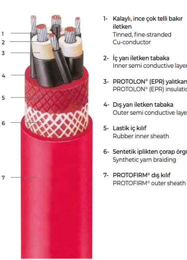
Conductor: High-purity, plain electrolytic copper conductors stranded to Class 5 fine-wire flexibility specifications in accordance with DIN EN 60228 / DIN VDE 0295. The fine stranding prevents work-hardening and micro-fracturing when the cable is repeatedly wound, unwound, and bent over small reel drums.
Inner Semi-Conductive Layer: A smooth, extruded semi-conductive compound layer applied directly over the stranded copper conductor. This layer eliminates air voids between individual conductor strands, equalizing the electrical field around the conductor and preventing localized electrical stress concentrations.
Insulation: Premium-grade Ethylene Propylene Rubber (EPR). EPR insulation provides outstanding dielectric strength, high thermal stability, low dielectric losses, and superior elasticity. It remains supple across extreme temperature ranges, resisting mechanical cracking during tight flexing.
Outer Semi-Conductive Layer: A fully bonded semi-conductive screen extruded over the EPR insulation. This layer creates a smooth, continuous electrode over the insulation, confining the electrical field within the insulation system and suppressing partial discharge.
Metallic Screen: A braided copper wire screen or composite copper tape/wire layer applied over each individual semi-conductive core. This metallic shield provides a low-resistance path for earth fault currents, shields adjacent communication circuits from electromagnetic interference, and enhances safety by ensuring any physical penetration contacts a grounded shield before reaching a live conductor.
Earth Conductor Configuration: The cable incorporates dedicated earth conductors, often split symmetrically into three earth cores located in the outer valleys of the main power cores. This symmetrical arrangement maintains thermal and mechanical balance during dynamic bending.
Inner Protective Sheath: A heavy-duty elastomeric inner jacket extruded directly over the assembled core lay-up. This inner cushion locks the cores into position, filling interstices and protecting the insulated cores from internal shearing forces.
Anti-Torsion Reinforcement: A embedded open-mesh textile or synthetic braid embedded between the inner and outer sheaths to prevent axial twisting forces from unwinding the internal lay-up.
Outer Protective Sheath: A rugged outer sheath composed of flame-retardant, oil-resistant, abrasion-resistant synthetic rubber compound (such as CPE or heavy-duty PCP). Feichun Cable formulates this outer jacket to resist tearing, gouging, solar UV radiation, and chemical exposure on mine sites.
3. Medium-Voltage Classifications and Technical Parameters
The (N)TSCGEWÖU cable family covers a wide range of medium-voltage classes to suit various machine power supplies and site distribution voltages. Depending on the application requirement, standard voltage ratings include:
3.6/6 kV
6/10 kV
8.7/15 kV
12/20 kV
18/30 kV
Because a single product designation covers multiple voltage ratings, engineers must cross-reference manufacturer datasheets to confirm exact voltage parameters, insulation wall thicknesses, and short-circuit ratings before specifying cables for site installations.
Representative Dimensional and Electrical Specifications
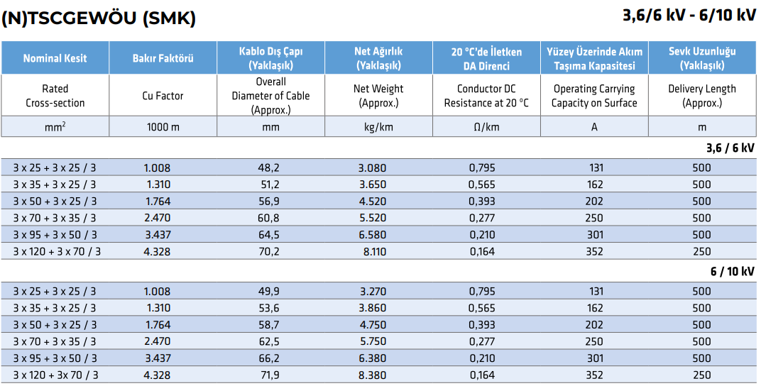
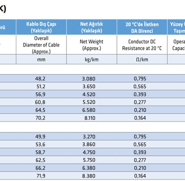
Datasheet values illustrate the physical dimensions, weights, resistance ratings, and current capacities across common cross-sections for 3.6/6 kV and 6/10 kV configurations:
For 3.6/6 kV Rated Configurations:
3 x 25 mm² power cores with split earth cores (3x25 + 3x25/3 mm²): approximate overall cable diameter of 48.2 millimeters, net cable weight of approximately 3,080 kilograms per kilometer, maximum DC conductor resistance at 20 °C of 0.795 Ohms per kilometer, continuous surface current carrying capacity of 131 Amperes, standard delivery length of 500 meters.
3 x 35 mm² power cores with split earth cores (3x35 + 3x25/3 mm²): approximate overall cable diameter of 51.2 millimeters, net cable weight of approximately 3,650 kilograms per kilometer, maximum DC conductor resistance at 20 °C of 0.565 Ohms per kilometer, continuous surface current carrying capacity of 162 Amperes, standard delivery length of 500 meters.
3 x 50 mm² power cores with split earth cores (3x50 + 3x25/3 mm²): approximate overall cable diameter of 56.9 millimeters, net cable weight of approximately 4,520 kilograms per kilometer, maximum DC conductor resistance at 20 °C of 0.393 Ohms per kilometer, continuous surface current carrying capacity of 202 Amperes, standard delivery length of 500 meters.
3 x 70 mm² power cores with split earth cores (3x70 + 3x35/3 mm²): approximate overall cable diameter of 60.8 millimeters, net cable weight of approximately 5,520 kilograms per kilometer, maximum DC conductor resistance at 20 °C of 0.277 Ohms per kilometer, continuous surface current carrying capacity of 250 Amperes, standard delivery length of 500 meters.
3 x 95 mm² power cores with split earth cores (3x95 + 3x50/3 mm²): approximate overall cable diameter of 64.5 millimeters, net cable weight of approximately 6,580 kilograms per kilometer, maximum DC conductor resistance at 20 °C of 0.210 Ohms per kilometer, continuous surface current carrying capacity of 301 Amperes, standard delivery length of 500 meters.
3 x 120 mm² power cores with split earth cores (3x120 + 3x70/3 mm²): approximate overall cable diameter of 70.2 millimeters, net cable weight of approximately 8,110 kilograms per kilometer, maximum DC conductor resistance at 20 °C of 0.164 Ohms per kilometer, continuous surface current carrying capacity of 352 Amperes, standard delivery length of 250 meters.
For 6/10 kV Rated Configurations:
3 x 25 mm² power cores with split earth cores (3x25 + 3x25/3 mm²): approximate overall cable diameter of 49.9 millimeters, net cable weight of approximately 3,270 kilograms per kilometer, maximum DC conductor resistance at 20 °C of 0.795 Ohms per kilometer, continuous surface current carrying capacity of 131 Amperes, standard delivery length of 500 meters.
3 x 35 mm² power cores with split earth cores (3x35 + 3x25/3 mm²): approximate overall cable diameter of 53.6 millimeters, net cable weight of approximately 3,860 kilograms per kilometer, maximum DC conductor resistance at 20 °C of 0.565 Ohms per kilometer, continuous surface current carrying capacity of 162 Amperes, standard delivery length of 500 meters.
3 x 50 mm² power cores with split earth cores (3x50 + 3x25/3 mm²): approximate overall cable diameter of 58.7 millimeters, net cable weight of approximately 4,750 kilograms per kilometer, maximum DC conductor resistance at 20 °C of 0.393 Ohms per kilometer, continuous surface current carrying capacity of 202 Amperes, standard delivery length of 500 meters.
3 x 70 mm² power cores with split earth cores (3x70 + 3x35/3 mm²): approximate overall cable diameter of 62.5 millimeters, net cable weight of approximately 5,750 kilograms per kilometer, maximum DC conductor resistance at 20 °C of 0.277 Ohms per kilometer, continuous surface current carrying capacity of 250 Amperes, standard delivery length of 500 meters.
3 x 95 mm² power cores with split earth cores (3x95 + 3x50/3 mm²): approximate overall cable diameter of 66.2 millimeters, net cable weight of approximately 6,380 kilograms per kilometer, maximum DC conductor resistance at 20 °C of 0.210 Ohms per kilometer, continuous surface current carrying capacity of 301 Amperes, standard delivery length of 500 meters.
3 x 120 mm² power cores with split earth cores (3x120 + 3x70/3 mm²): approximate overall cable diameter of 71.9 millimeters, net cable weight of approximately 8,380 kilograms per kilometer, maximum DC conductor resistance at 20 °C of 0.164 Ohms per kilometer, continuous surface current carrying capacity of 352 Amperes, standard delivery length of 250 meters.
4. Mining Equipment Applications and Australian Operational Scenarios
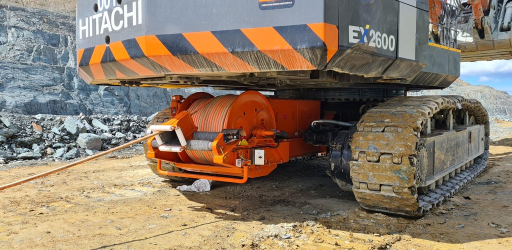
The (N)TSCGEWÖU cable is engineered for mobile machinery that requires continuous medium-voltage power while moving dynamically. Across Australian mining and material handling facilities, typical equipment installations include:
Bucket Wheel Excavators and Draglines
In large open-cut coal mines across Queensland and New South Wales, draglines and bucket wheel excavators operate continuously. These massive machines move periodically as they cut through overburden, requiring heavy-duty reeling cables that can handle continuous reel winding, payout tension, and abrasive contact with rough rock floors.
Electric Mining Shovels
Electric rope shovels in Pilbara iron ore operations handle heavy digging cycles. The trailing or reeling power cable must absorb severe vibration, high acceleration, and sudden directional shifts without experiencing internal core migration or shield displacement.
Stacker Reclaimers and Port Loaders
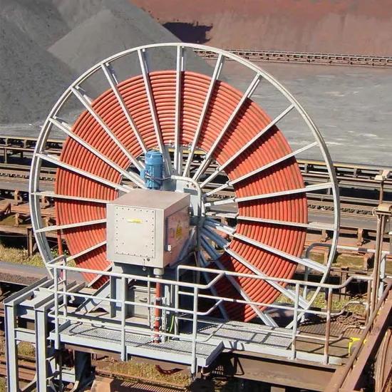
In bulk commodity export terminals—such as Port Hedland, Newcastle, and Gladstone—stacker reclaimers move up and down long stockyards on rail tracks. Motorised cable reels continuously pay out and retract medium-voltage power cables over hundreds of meters. The (N)TSCGEWÖU cable's high reel-drum stability ensures uniform layer winding without binding.
Mobile Crushers and Continuous Miners
In large-scale quarrying, civil infrastructure, and underground continuous mining operations, mobile crushers and roadheaders require flexible medium-voltage trailing lines that resist mechanical crushing, oil contamination, and tight-radius bending around guide fairleads.
Australian Weather and Site Considerations
Australia’s mine sites subject equipment to severe environmental extremes:
Pilbara Solar Exposure: Summer ambient temperatures routinely exceed 45 °C, pushing solar-heated black cable sheaths beyond 75 °C. The high-grade CPE outer sheath and 90 °C rated EPR insulation prevent thermal softening and maintain tensile strength under high UV exposure.
Bowen Basin Rain and Mud: During monsoon rain events, open-cut pits turn to thick mud and standing water. The oil- and water-resistant rubber sheath prevents moisture ingress, while the individual core screening maintains field uniformity in wet conditions.
Dust and Abrasive Ground Cover: Ground trailing cables are exposed to sharp iron ore, basalt, and granite fragments. The heavy-duty elastomeric outer sheath resists tearing, gouging, and surface abrasion during machine travel.
5. Mechanical Performance and Reeling Dynamics
The mechanical design of the (N)TSCGEWÖU cable is engineered specifically to prevent mechanical fatigue during continuous reeling. Key dynamic performance parameters include:
Drum Reeling Stability
When wound onto a motorised reel drum under tension, a cable experiences radial compression, axial tension, and flexural stress simultaneously. The core lay-up of (N)TSCGEWÖU utilizes balanced lay lengths and cushioned rubber fillers that distribute compression evenly across all three main cores, preventing the cable from going out-of-round.
Minimum Bending Radius Adherence
Maintaining the recommended minimum bending radius is essential for protecting the semi-conductive layers and copper screens from mechanical damage. For dynamic reeling service, the minimum bending radius is typically specified at 10 to 12 times the overall cable diameter (10-12 x D), depending on travel speed and drum geometry. For fixed installation, this radius can be reduced to 6 x D.
Tensile Load Management
The maximum permissible tensile load applied to the copper conductors is generally capped at 15 Newtons per square millimeter of combined power conductor cross-section. On long-travel stacker reclaimers or draglines with high payout tension, the central strain relief element or integrated outer braid absorbs dynamic tensile spikes, keeping stress off the copper conductors.
Torsional Resistance
Equipment rotation and S-bend guide sheaves introduce torsional torque into the cable assembly. The embedded anti-torsion braid braid locks the inner and outer sheaths together, resisting torsional rotation up to ±25 degrees per meter and preventing internal core corkscrewing.
6. Why Ordinary Medium-Voltage Cables Fail in Reeling Service
Industrial sites occasionally attempt to deploy standard fixed-installation medium-voltage cables—such as XLPE-insulated steel wire armoured (SWA) or standard unarmoured PVC/XLPE distribution cables—for mobile equipment power feeds. Standard cables fail quickly when subjected to dynamic movement:
First, standard XLPE insulation is relatively rigid compared to flexible EPR. Repeated flexing causes micro-cracking within rigid XLPE and damages extruded semi-conductive layers, leading to partial discharge breakdown and insulation failure.
Second, standard Class 2 stranded conductors flex poorly. Repeated bending on a cable drum work-hardens rigid copper wires, causing individual strands to snap and puncture adjacent insulation layers.
Third, standard PVC or polyethylene outer jackets lack the tear resistance, elasticity, and recovery required for reel winding. Under tension, plastic jackets deform permanently, splits open under UV exposure, and tear when dragged over rock.
Fourth, fixed-installation cables lack internal anti-torsion braiding. As the reel turns, axial torque twists the internal cores, causing core displacement, phase-to-phase short circuits, and sheath buckling.
By contrast, the (N)TSCGEWÖU cable is built from fine-wire conductors, elastomeric EPR insulation, semi-conductive stress-control layers, individual copper shielding, and reinforced rubber jacketing, ensuring long service life under continuous dynamic flexing.
7. Comparison: (N)TSCGEWÖU vs. Fixed-Installation MV Cables
Comparing the (N)TSCGEWÖU cable with conventional fixed-installation MV distribution cables highlights key structural and performance differences:
Conductor Flexibility: (N)TSCGEWÖU uses Class 5 fine-wire flexible copper, whereas standard MV distribution cables (such as XLPE/PVC types) use Class 2 compact stranded conductors designed purely for static tray or underground duct installation.
Insulation System: (N)TSCGEWÖU uses elastomeric EPR insulation for maximum dynamic flex fatigue resistance. Standard MV cables use rigid cross-linked polyethylene (XLPE) optimized for static thermal efficiency rather than dynamic motion.
Sheathing Materials: (N)TSCGEWÖU employs a dual-sheath elastomeric compound (such as CPE or heavy-duty rubber) with embedded anti-torsion braiding. Standard MV cables use PVC, polyethylene, or light polyolefin jackets that crack under dynamic bending.
Application Environment: (N)TSCGEWÖU is purpose-built for continuous drum reeling, trailing over ground, and moving booms on mining machinery. Standard MV distribution cables are restricted to fixed cable trays, direct burial, or static underground conduits.
8. Essential Selection Checklist for Engineers and Procurement
When specifying (N)TSCGEWÖU cables for mine site equipment upgrades or new machine builds across Australia, electrical engineering teams should systematically verify the following criteria:
System Voltage Rating: Confirm the operating line-to-line voltage matches the cable rating (e.g., 3.6/6 kV, 6/10 kV, 8.7/15 kV).
Continuous Current Demand: Select the conductor cross-section (e.g., 25 mm² through to 120 mm²) based on machine full-load current, applying drum derating factors for multi-layer winding.
Earth Fault Capacity: Ensure the total cross-section of the split earth conductors and copper screens meets site protection relay clearing times and fault current levels.
Reel Drum Compatibility: Cross-reference outer cable diameter and weight against drum flange width, spool capacity, and drive torque.
Minimum Bending Radius: Verify that machine guide sheaves, changing rollers, and reel hub diameters meet the 10-12 x D dynamic bending radius limit.
Travel Speed and Tensile Force: Confirm that peak payout acceleration and reeling speed stay within the maximum permissible tensile load limits.
Environmental Hazards: Confirm that outer sheath compounds provide adequate resistance to site-specific hazards, including direct solar UV, hydraulic oil exposure, and extreme pit water contact.
Manufacturer Quality Verification: Source cables from recognized manufacturers like Feichun Cable to guarantee strict adherence to VDE standards, core concentricity, and full factory high-voltage discharge testing.
9. Conclusion
The (N)TSCGEWÖU cable is a heavy-duty medium-voltage reeling cable engineered to withstand the severe mechanical and environmental conditions of open-cut mining and mobile material handling. By combining fine-wire Class 5 conductors, resilient EPR insulation, extruded semi-conductive stress control layers, individual copper core screens, and a reinforced rubber outer sheath, it ensures long service life under continuous dynamic movement.
Whether powering bucket wheel excavators in coal mines, electric shovels in iron ore pits, or stacker reclaimers at coastal export terminals, specifying purpose-built (N)TSCGEWÖU cables minimizes unscheduled downtime, protects capital equipment, and maintains high mine site productivity. For detailed datasheets, custom length orders, and engineering support tailored to Australian mine conditions, consult the technical team at Feichun Cable.
How to Reach Us
Get in Touch
SiteMap
Product Catalogue
Festoon Cable
Shore Power Cable




Scan to add us on WeChat