
High-Speed MV Mining Reeling Cable Guide: (N)TSKCGEWÖU Integrated Power, Control, and Optical Solutions for Australian Mines
Detailed engineering guide to the (N)TSKCGEWÖU flexible medium-voltage reeling cable. Learn how its combined power, control cores, earth monitoring, and fibre optic elements support high-speed mining machinery in Australian opencast and underground operations.
7/21/202615 min read
1. Introduction
(N)TSKCGEWÖU is a flexible medium-voltage mining cable designed for high-speed reeling, combining power cores, control cores, earth monitoring, and fibre optics for large mobile equipment. Across Australia’s mining sector—from the open-cut coal mines of Queensland’s Bowen Basin and the Hunter Valley to the iron ore pits of the Pilbara and underground operations nationwide—heavy mobile machinery operates under severe mechanical, thermal, and environmental stress.
Modern mining equipment, such as high-capacity excavators, continuous miners, electric draglines, mobile crushers, and stacker reclaimers, requires more than just high-voltage electrical power. These automated machines rely on continuous telemetry, temperature monitoring, brake control feedback, earth continuity checking, and real-time data transmission while moving at high travel speeds.
Running multiple separate trailing lines for power, control, and data increases cable weight, causes tangling on reeling drums, and significantly raises the risk of mechanical damage on active mine sites.
The (N)TSKCGEWÖU cable addresses these challenges through an integrated, multi-functional design. Engineered for high-speed reeling duty under dynamic torsional stress and multi-plane deflection, this cable incorporates medium-voltage power cores, auxiliary control cores, dedicated earth monitoring elements, and optional fibre optic cores within a compact, weight-optimized rubber assembly.
Supplied for resource projects by specialists like Feichun Cable, the (N)TSKCGEWÖU cable serves as a comprehensive power and data solution for automated, heavy-duty mining machinery.
2. Deciphering the (N)TSKCGEWÖU Designation and Structural Architecture
The technical designation (N)TSKCGEWÖU follows established European and VDE standardized naming conventions for heavy-duty trailing and reeling cables, with specific letters denoting its internal component configuration:
The bracketed prefix (N) indicates a standardized VDE-based cable construction incorporating enhanced, specialized materials optimized for high-stress dynamic applications.
The T designates a dynamic trailing or reeling cable family built for mobile machinery.
The S highlights specialized heavy-duty structural reinforcement engineered to withstand severe dynamic mechanical loading, high reeling speeds, and torsional forces.
The K is the critical distinguishing letter in this designation. It identifies the inclusion of integrated control cores (Kontrolladern) alongside the main medium-voltage power cores.
The C refers to individual core screening, where metallic shields or composite semi-conductive layers enclose each main power core to control dielectric stress and provide earth fault protection.
The G specifies ethylene propylene rubber (EPR) or high-grade elastomeric insulation.
The E indicates extruded semi-conductive stress-control layers applied directly over the conductors and insulation screens.
The W denotes high weather, UV, ozone, and environmental resistance.
Finally, the ÖU designation highlights a heavy-duty, oil-resistant, flame-retardant synthetic rubber outer sheath compound.
While slight naming conventions may vary across global cable suppliers, electrical engineers should focus on the verified physical structure: a high-speed, weight-reduced medium-voltage reeling cable that unifies power distribution, operational control, safety ground monitoring, and optical data transfer within a single protective sheath.
3. Scope of Main Mining Applications
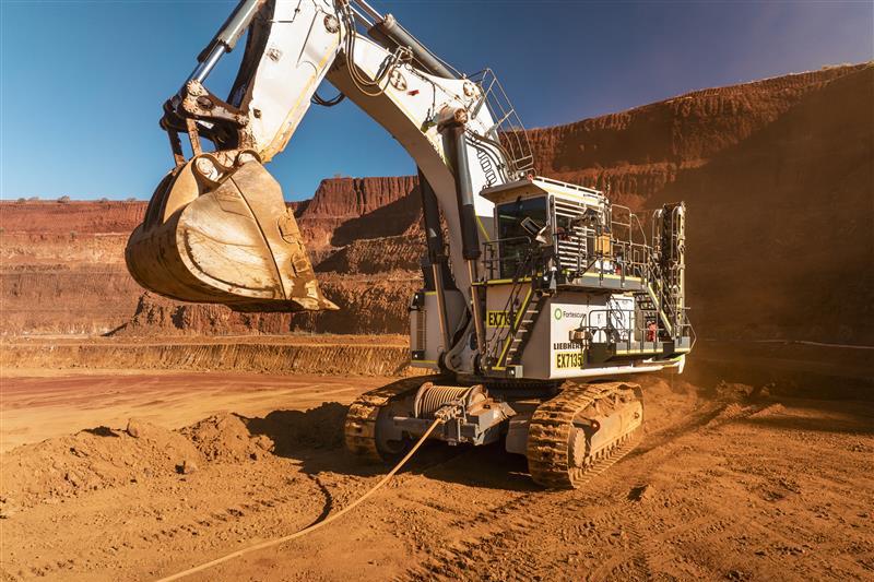
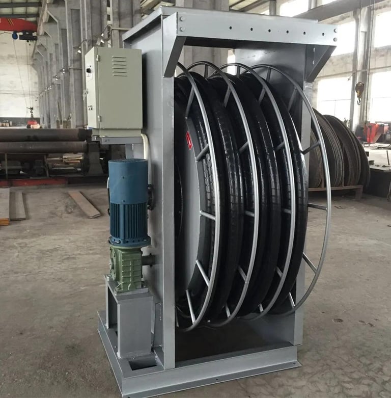
The (N)TSKCGEWÖU cable is engineered for mobile machinery subjected to frequent bending, multi-axial rotation, high acceleration, and rapid spooling. It operates across both opencast surface mining pits and demanding underground mine environments.
Key machinery installations across Australia include:
Electric Mining Excavators and Shovels
Large electric rope shovels in open-cut iron ore and coal operations require high-voltage power coupled with continuous brake control and temperature feedback. The cable’s ability to pay out and rewind rapidly without twisting ensures unhindered shovel maneuvering along the pit bench.
Tunneling Machines and Roadheaders
In underground development drives and civil tunneling projects, roadheaders and continuous miners negotiate tight curves and changing gradient planes. The cable withstands severe multi-plane deflection and continuous dragging across abrasive rock floors.
Draglines and Bucket Wheel Excavators
Draglines operating in large open-cut strip mines move substantial volumes of overburden. The (N)TSKCGEWÖU cable supports heavy dynamic tension and rapid spooling on large motorised reels during machine relocation.
Stacker Reclaimers and Bulk Material Handling Systems
At coastal export terminals—such as Port Hedland, Gladstone, and Newcastle—and inland rail loadout facilities, stacker reclaimers travel continuously along stockyard rails. The cable feeds medium-voltage drive power while transmitting automated positioning signals and camera feeds back to central control stations.
Mobile Crushers, Hoists, and Conveyor Drives
In pit-top processing plants and in-pit crushing and conveying (IPCC) systems, mobile crushing units require flexible power connections that can be relocated easily without running multiple trailing cables.
4. Layered Cable Construction Breakdown
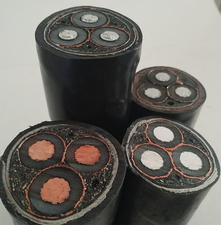
The internal architecture of the (N)TSKCGEWÖU cable is engineered to balance weight reduction with structural stability under continuous motion. Every component layer serves a specific electrical, mechanical, or communication function:
Phase Conductors: Flexible Class 5 tinned copper conductors stranded in accordance with DIN EN 60228 / DIN VDE 0295 standards. Tinned copper prevents corrosion caused by atmospheric sulfur and moisture, while fine wire stranding ensures maximum flex fatigue resistance during repeated reeling cycles.
Phase Insulation System: High-grade rubber compound insulation extruded over the phase conductors. The insulation system incorporates an inner semi-conductive tape over the conductor, an inner extruded semi-conductive rubber layer, the primary EPR insulation, and an outer extruded semi-conductive rubber layer. This layered approach manages the electrical field uniformly, preventing localized partial discharges.
Auxiliary Control Cores: Flexible insulated control conductors laid up within the outer interstices of the main assembly. These cores carry low-voltage auxiliary signals, system interlocks, and sensor diagnostics.
Earth Conductor and Earth Monitoring: Class 5 flexible tinned copper earth conductors distributed symmetrically within the cable assembly. Dedicated pilot or ground-monitoring wires provide continuous electrical continuity monitoring between the machine frame and the supply switchboard.
Central Filler: A semi-conductive compound central core element. This filler acts as a mechanical anchor for the laid-up cores, absorbing radial compression forces during tight spooling on reel drums.
Integrated Fibre Optics: Optional optical fiber elements containing 50/125 multimode, 62.5/125 multimode, or 9/125 singlemode fibers housed within crush-resistant protective buffer tubes.
Inner Sheath: A robust rubber compound inner sheath extruded directly over the laid-up core assembly to lock components in position and buffer against internal friction.
Anti-Twist Reinforcement: An open-mesh polyester braid reinforcement embedded between the inner and outer rubber sheaths. This braid provides high torsional resistance, preventing axial twisting forces from unwinding the inner cores.
Outer Sheath: A heavy-duty, flame-retardant, oil-resistant rubber compound outer jacket finished in a high-visibility red color. Feichun Cable formulates this outer jacket to resist tearing, impact, moisture ingress, and intense solar UV degradation.
5. Integrating Power, Control, and Auxiliary Functions
The primary advantage of the (N)TSKCGEWÖU cable lies in its multi-functional design. Standard medium-voltage reeling cables only provide three power phase cores and split earth conductors. In contrast, the (N)TSKCGEWÖU cable incorporates dedicated control cores (K-cores) within the same outer sheath.
In modern automated mining operations, mobile equipment requires continuous low-voltage control circuits for:
Machine brake control and safety interlocks.
Winding motor temperature sensing and thermal protection.
Emergency stop loops and system feedback loops.
Operational status telemetry and auxiliary power supplies.
By integrating these control circuits directly into the medium-voltage trailing cable, mine operators eliminate the need for secondary control trailing lines or wireless control systems, which can suffer from signal interference in deep open-cut pits or underground stopes. This unified layout simplifies reel drum geometry, reduces overall trailing cable drag weight, and minimizes downtime caused by damaged auxiliary wiring.
6. Earth Monitoring and Advanced Electrical Safety
Safety is a top priority in Australian mining operations. High fault currents in medium-voltage mobile machinery pose severe risks of electric shock, arc flash, and equipment fire if protective grounding systems fail.
The (N)TSKCGEWÖU cable features integrated earth monitoring (pilot) conductors alongside its primary earth conductors. Connected to continuous earth-continuity monitoring relays at the substation or switchboard, these monitoring wires establish a low-voltage circuit that checks grounding continuity in real time.
If the cable suffers mechanical impact—such as being run over by a haul truck or pinched against a pit wall—the earth monitoring loop detects conductor stretching or insulation breakdown instantly, tripping the main circuit breaker before a full phase-to-earth fault or open-circuit ground condition occurs. This continuous safety checking protects site personnel and prevents catastrophic electrical damage to high-value mining assets.
7. Integrated Fibre Optics for High-Speed Data Transmission
As Australian mine sites transition toward automated shovels, remote-controlled drills, and real-time fleet management, bandwidth requirements at the pit face have increased significantly.
To support high-speed data transmission, the (N)TSKCGEWÖU cable can be configured with integrated fibre optic core packages. Available optical fiber options include:
50/125 Multimode Fiber: Ideal for short-to-medium distance high-speed data transmission and local machine control network backbones.
62.5/125 Multimode Fiber: Suitable for legacy optical communications networks and industrial control protocols.
9/125 Singlemode Fiber: Optimized for long-distance, high-bandwidth data transmission, supporting high-definition video feeds, real-time LIDAR mapping data, and automated machine control signals back to distant central operations centers.
Housed within gel-filled, crush-resistant central or interstitial tubes, these optical fibers are protected from mechanical crushing and dynamic flex fatigue during high-speed reeling operations.
8. Voltage Ratings and Field Performance Classes
The (N)TSKCGEWÖU cable family covers four standard medium-voltage operating classes:
3.6/6 kV (Test voltage: 11 kV AC for 5 minutes)
6/10 kV (Test voltage: 17 kV AC for 5 minutes)
8.7/15 kV (Test voltage: 24 kV AC for 5 minutes)
12/20 kV (Test voltage: 29 kV AC for 5 minutes)
These voltage ratings make the cable suitable for standard Australian mine site reticulation systems, including 6.6 kV and 11 kV machinery power networks. Choosing the correct voltage class depends on the machine transformer primary voltage, site earthing configuration, and local mining electrical regulations.
9. Dynamic Mechanical Parameters and High-Speed Performance
The mechanical parameters of the (N)TSKCGEWÖU cable are tailored specifically for dynamic, high-speed reeling applications:
Maximum Working Speed: Rated for reeling travel speeds up to 240 meters per minute (240 m/min), making it ideal for rapid-travel shuttle cars, fast stacker reclaimers, and high-speed crane hoists.
Maximum Tensile Load: Capable of enduring continuous pulling tension up to 30 Newtons per square millimeter (30 N/mm²) across total conductor cross-sections, supported by high-tensile aramid/polyester reinforcement elements.
Maximum Torsional Stress: Formulated to withstand torsional rotation up to plus or minus 25 degrees per meter (±25 °/m) without structural deformation or core corkscrewing.
Minimum Bending Radius: Specified at 6 times the overall cable diameter (6 x D) for fixed installations, and 10 times the overall cable diameter (10 x D) for dynamic flexing and reeling service.
Representative Dimensional, Weight, and Ampacity Data
Engineering data across supported voltage classes and cross-sections illustrates the cable's physical properties:
For 3.6/6 kV Rated Configurations:
3 x 25 mm² power cores plus 3 x 25 mm² earth/control cores: nominal overall outer diameter of 21.8 mm, nominal weight of 2,380 kg/km, maximum tensile load of 1,500 N.
3 x 35 mm² power cores plus 3 x 25 mm² earth/control cores: nominal overall outer diameter of 43.8 mm, nominal weight of 2,920 kg/km, maximum tensile load of 2,100 N.
3 x 50 mm² power cores plus 3 x 25 mm² earth/control cores: nominal overall outer diameter of 46.9 mm, nominal weight of 3,520 kg/km, maximum tensile load of 3,000 N.
3 x 70 mm² power cores plus 3 x 35 mm² earth/control cores: nominal overall outer diameter of 50.7 mm, nominal weight of 4,430 kg/km, maximum tensile load of 4,200 N.
3 x 95 mm² power cores plus 3 x 50 mm² earth/control cores: nominal overall outer diameter of 56.7 mm, nominal weight of 5,580 kg/km, maximum tensile load of 5,700 N.
3 x 120 mm² power cores plus 3 x 70 mm² earth/control cores: nominal overall outer diameter of 60.5 mm, nominal weight of 6,770 kg/km, maximum tensile load of 7,200 N.
3 x 150 mm² power cores plus 3 x 70 mm² earth/control cores: nominal overall outer diameter of 67.2 mm, nominal weight of 8,260 kg/km, maximum tensile load of 9,000 N.
For 6/10 kV Rated Configurations:
3 x 25 mm² power cores plus 3 x 25 mm² earth/control cores: nominal overall outer diameter of 39.8 mm, nominal weight of 2,380 kg/km, maximum tensile load of 1,500 N.
3 x 35 mm² power cores plus 3 x 25 mm² earth/control cores: nominal overall outer diameter of 43.8 mm, nominal weight of 2,920 kg/km, maximum tensile load of 2,100 N.
3 x 50 mm² power cores plus 3 x 25 mm² earth/control cores: nominal overall outer diameter of 46.9 mm, nominal weight of 3,520 kg/km, maximum tensile load of 3,000 N.
3 x 70 mm² power cores plus 3 x 35 mm² earth/control cores: nominal overall outer diameter of 50.7 mm, nominal weight of 4,430 kg/km, maximum tensile load of 4,200 N.
3 x 95 mm² power cores plus 3 x 50 mm² earth/control cores: nominal overall outer diameter of 56.7 mm, nominal weight of 5,640 kg/km, maximum tensile load of 5,700 N.
3 x 120 mm² power cores plus 3 x 70 mm² earth/control cores: nominal overall outer diameter of 60.5 mm, nominal weight of 6,830 kg/km, maximum tensile load of 7,200 N.
3 x 150 mm² power cores plus 3 x 70 mm² earth/control cores: nominal overall outer diameter of 67.2 mm, nominal weight of 8,320 kg/km, maximum tensile load of 9,000 N.
For 8.7/15 kV Rated Configurations:
3 x 25 mm² power cores plus 3 x 25 mm² earth/control cores: nominal overall outer diameter of 45.6 mm, nominal weight of 2,860 kg/km, maximum tensile load of 1,500 N.
3 x 35 mm² power cores plus 3 x 25 mm² earth/control cores: nominal overall outer diameter of 47.0 mm, nominal weight of 3,210 kg/km, maximum tensile load of 2,100 N.
3 x 50 mm² power cores plus 3 x 25 mm² earth/control cores: nominal overall outer diameter of 50.3 mm, nominal weight of 3,830 kg/km, maximum tensile load of 3,000 N.
3 x 70 mm² power cores plus 3 x 35 mm² earth/control cores: nominal overall outer diameter of 55.9 mm, nominal weight of 5,000 kg/km, maximum tensile load of 4,200 N.
3 x 95 mm² power cores plus 3 x 50 mm² earth/control cores: nominal overall outer diameter of 59.3 mm, nominal weight of 5,870 kg/km, maximum tensile load of 5,700 N.
3 x 120 mm² power cores plus 3 x 70 mm² earth/control cores: nominal overall outer diameter of 65.0 mm, nominal weight of 7,370 kg/km, maximum tensile load of 7,200 N.
3 x 150 mm² power cores plus 3 x 70 mm² earth/control cores: nominal overall outer diameter of 69.7 mm, nominal weight of 8,590 kg/km, maximum tensile load of 9,000 N.
For 12/20 kV Rated Configurations:
3 x 25 mm² power cores plus 3 x 25 mm² earth/control cores: nominal overall outer diameter of 47.3 mm, nominal weight of 3,080 kg/km, maximum tensile load of 1,500 N.
3 x 35 mm² power cores plus 3 x 25 mm² earth/control cores: nominal overall outer diameter of 49.7 mm, nominal weight of 3,460 kg/km, maximum tensile load of 2,100 N.
3 x 50 mm² power cores plus 3 x 20 mm² earth/control cores: nominal overall outer diameter of 54.6 mm, nominal weight of 4,310 kg/km, maximum tensile load of 3,000 N.
3 x 70 mm² power cores plus 3 x 35 mm² earth/control cores: nominal overall outer diameter of 58.4 mm, nominal weight of 5,310 kg/km, maximum tensile load of 4,200 N.
3 x 95 mm² power cores plus 3 x 50 mm² earth/control cores: nominal overall outer diameter of 62.0 mm, nominal weight of 6,180 kg/km, maximum tensile load of 5,700 N.
3 x 120 mm² power cores plus 3 x 70 mm² earth/control cores: nominal overall outer diameter of 67.6 mm, nominal weight of 7,730 kg/km, maximum tensile load of 7,200 N.
3 x 150 mm² power cores plus 3 x 70 mm² earth/control cores: nominal overall outer diameter of 72.2 mm, nominal weight of 8,970 kg/km, maximum tensile load of 9,000 N.
Current Carrying Capacity and Reel Layer Derating (3.6/6 kV and 6/10 kV)
Thermal management is critical when reeling cables operate partially wound on motor drums. Ampacity ratings across installation layouts include:
25 mm² Conductor: 131 A laying on ground, 138 A free in air. Reeled ampacity: 105 A (1 layer), 80 A (2 layers), 64 A (3 layers), 55 A (4 layers), 50 A (5 layers), 35 A (6 layers), 29 A (7 layers).
35 mm² Conductor: 162 A laying on ground, 170 A free in air. Reeled ampacity: 130 A (1 layer), 99 A (2 layers), 79 A (3 layers), 68 A (4 layers), 62 A (5 layers), 44 A (6 layers), 36 A (7 layers).
50 mm² Conductor: 202 A laying on ground, 212 A free in air. Reeled ampacity: 162 A (1 layer), 123 A (2 layers), 99 A (3 layers), 85 A (4 layers), 77 A (5 layers), 55 A (6 layers), 44 A (7 layers).
70 mm² Conductor: 250 A laying on ground, 263 A free in air. Reeled ampacity: 200 A (1 layer), 153 A (2 layers), 123 A (3 layers), 105 A (4 layers), 95 A (5 layers), 68 A (6 layers), 55 A (7 layers).
95 mm² Conductor: 301 A laying on ground, 316 A free in air. Reeled ampacity: 241 A (1 layer), 184 A (2 layers), 147 A (3 layers), 126 A (4 layers), 114 A (5 layers), 81 A (6 layers), 66 A (7 layers).
120 mm² Conductor: 352 A laying on ground, 370 A free in air. Reeled ampacity: 282 A (1 layer), 215 A (2 layers), 172 A (3 layers), 148 A (4 layers), 134 A (5 layers), 95 A (6 layers), 77 A (7 layers).
150 mm² Conductor: 404 A laying on ground, 424 A free in air. Reeled ampacity: 323 A (1 layer), 246 A (2 layers), 198 A (3 layers), 170 A (4 layers), 154 A (5 layers), 109 A (6 layers), 89 A (7 layers).
10. Thermal and Environmental Resistance Performance
The (N)TSKCGEWÖU cable is built to handle harsh atmospheric and operational conditions:
Operating Temperature Range (Flexing Service): -30 °C up to +90 °C.
Operating Temperature Range (Fixed Installation): -50 °C up to +90 °C.
Maximum Short-Circuit Conductor Temperature: 250 °C.
High-Visibility Outer Jacket: Finished in bright red elastomeric rubber compound, aiding visual recognition by equipment operators and haul truck drivers to minimize accidental impact damage on active mine sites.
In northern Australian mining operations—such as the Pilbara or Gulf region—black cable sheaths exposed to direct sunlight can experience high surface temperatures. The red outer sheath compound used on (N)TSKCGEWÖU reflects more radiant solar energy than standard black jackets while providing UV and ozone resistance, maintaining flexibility during heavy continuous flexing.
11. Technical Comparison: (N)TSCGEWÖU vs. (N)TSKCGEWÖU
Understanding the functional differences between base reeling cables and advanced variants assists site engineers in selecting the right product:
Base (N)TSCGEWÖU Cable: Optimized primarily for medium-voltage power delivery and ground safety. It incorporates three power phase cores and split earth conductors within a heavy-duty rubber jacket. It is ideal for basic machinery requiring straightforward high-voltage power transmission.
Advanced (N)TSKCGEWÖU Cable: An upgraded multi-functional cable platform. It combines medium-voltage power phase cores and split earth conductors with auxiliary control cores, earth continuity monitoring elements, and optional fibre optic packages.
In short:
TSCGEWÖU = Power + Ground Safety Reeling Cable.
TSKCGEWÖU = Power + Control + Earth Monitoring + High-Speed Data Cable.
For modern automated mining equipment that relies on continuous sensor telemetry, remote video feeds, or integrated safety interlocks, the (N)TSKCGEWÖU cable provides a complete single-cable solution.
12. Why Standard Fixed MV Cables Fail in Mining Reeling Applications
Deploying standard fixed-installation medium-voltage cables—such as XLPE-insulated steel wire armoured (SWA) or standard unarmoured PVC distribution cables—on mobile mining equipment frequently leads to premature electrical failure:
Conductor Snap: Standard Class 2 rigid conductors work-harden and snap when wound repeatedly over small reel drums, causing open-circuit faults and localized arcing.
Insulation Micro-Cracking: Standard XLPE insulation lacks the flexural elasticity of EPR rubber. Repeated bending induces micro-cracking within the dielectric, causing partial discharge breakdown.
Core Corkscrewing: Fixed cables lack integrated anti-torsion braiding. As the reel turns, torsional torque twists the internal conductors, pushing cores through the outer sheath.
Complex Multi-Cable Trailing: Using separate cables for power, brake control, and data transmission increases cable drag weight, causes line tangling on the pit bench, and doubles maintenance overheads.
The (N)TSKCGEWÖU cable eliminates these vulnerabilities through its fine-wire Class 5 tinned copper stranding, flexible EPR insulation system, polyester anti-torsion braid, and integrated multi-functional core layout.
13. Procurement and Engineering Selection Checklist
Mine site electrical engineers and procurement specialists should evaluate ten key technical criteria before ordering (N)TSKCGEWÖU trailing cables:
Nominal Operating Voltage: Confirm site reticulation voltage (3.6/6 kV, 6/10 kV, 8.7/15 kV, or 12/20 kV).
Power Conductor Size: Calculate continuous full-load current and apply drum layer derating factors based on operating spool depth.
Auxiliary Control Core Count: Specify the required number of control cores and signal voltage ratings for brake circuits and sensors.
Earth Continuity Monitoring Requirements: Confirm switchboard relay parameters for ground continuity pilot loop compatibility.
Data Transmission Bandwidth: Select appropriate fibre optic cores (50/125, 62.5/125 multimode, or 9/125 singlemode) if real-time video or automated telemetry is required.
Reel Drum Mechanical Alignment: Check overall cable outer diameter and total weight against drum flange width and motor drive torque limits.
Minimum Bending Radius: Verify that machine guide sheaves and reel hubs adhere to the 10 x D dynamic flex limit.
Reeling Speed and Acceleration: Ensure travel speeds do not exceed the 240 m/min operational limit.
Environmental Exposure: Verify resistance to direct solar UV, hydraulic oil exposure, acid mine water, and ambient temperatures.
Supplier Quality Certification: Source from experienced manufacturers like Feichun Cable to ensure strict compliance with VDE standards, core concentricity, and factory partial discharge testing.
14. Conclusion
The (N)TSKCGEWÖU cable is a flexible medium-voltage mining reeling cable engineered for high-speed mobile machinery. By unifying medium-voltage power cores, auxiliary control wiring, continuous earth monitoring, and optical fiber communications within a single weight-optimized, rubber-sheathed assembly, it simplifies trailing cable management on complex mine sites.
With a working travel speed rating up to 240 m/min, 30 N/mm² tensile strength, ±25 °/m torsional tolerance, and a high-visibility red outer sheath, it withstands demanding open-cut and underground mining environments across Australia. Specifying purpose-built (N)TSKCGEWÖU cables helps mine operators protect capital equipment, reduce trailing line maintenance, and maintain continuous operational productivity.
For technical datasheets, custom fiber/control core configurations, and supply options tailored to Australian mine sites, consult the technical team at Feichun Cable.
How to Reach Us
Get in Touch
SiteMap
Product Catalogue
Festoon Cable
Shore Power Cable




Scan to add us on WeChat